

Evcon DGAM056BDD, DGAT056BDD, DGAT070BDD, DGAT075BDD, DGAT090BDD Installation Instructions Manual
...
INSTALLATION INSTRUCTIONS
SEALED COMBUSTION
DOWNFL OW GAS FURNACES
Forced Draft with Direct Ignition (Hot Surface)
FURNACE SET---UP CHECK LIST
IMPORTANT: ONLY INDIVIDUALS HAVING PROVEN EXPERIENCE WITH THIS TYPE OF EQUIPMENT
SHOULD ATTEMPT TO PERFORM SET --UP.
- HAS ROOF JACK CROWN BEEN CORRECTLY
INSTALLED?
- HASFURNACEGASVALVEANDBURNERORIFICE BEEN CORRECTLY CONVERTED FOR L .P.
GAS WHERE APPLICABLE?
- HASFURNACEGASVALVEBEENDE---RATED
FOR ALTITUDES ABOVE 2000 FEET WHERE
APPLICABLE?
- IS GAS LINE OUTLET PRESSURE PROPERLY
IMPORTANT: PROPER FURNACE SET--UP AND ADJUSTMENT IS THE RESPONSIBILITY OF THE
RETAILER/HOMEOWNER AND IS NOT COVERED UNDER WARRANTY.
DLAS MODELS
(No Coil Cabinet)
SET FOR FUEL TYPE? (NATURALGASIS3.5”
W.C.; L. P . IS 10” W.C.)
- IS PRIMARY AIR PROPERLY ADJUSTED PER
INSTALLATION INSTRUCTIONS?
- IS CROSS ---OVER DUCT INSTALLED PER
HOME BUILDER AND EVCON INSTALLATION
INSTRUCTIONS?
- HAS FURNACE BEEN OPERATED THROUGH A
COMPLETE HEATING CYCLE?
DGAT & DGAM MODELS
(With Built-- In Coil Cabinet)
For Installation In:
1. Manufactured (Mobile) Homes
2. Recreational Vehicles & Park
Models
3. Modular Homes & Buildings

TABLE OF CONTENTS
GENERAL SPECIFICATIONS AND INSTRUCTIONS 4.......................
FURNACE SPECIFICATIONS 5...........................................
INSTALLATION STANDARDS 6...........................................
Comply with Local Codes 6......................................................
HIGH ALTITUDE INSTALLATIONS 6...............................................
MINIMUM FURNACE CLEARANCES 6............................................
RETURN AIR REQUIREMENTS 7.................................................
CLOSET INSTALLATIONS 7......................................................
Furnace to Closet Door Clearance — Greater than 6 Inches 7........................
Additional Requirements 7.......................................................
Floor or Ceiling Return Air System 7..............................................
SPECIAL CLOSET INSTALLATIONS 8.............................................
Furnace to Closet Door Clearance — Greater than 1 Inch and Less than 6 Inches 8....
Furnace to Closet Door Clearance — Less than 1 Inch 8............................
AIR DISTRIBUTION SYSTEMS 9..................................................
ROOF JACKS 10.........................................................
Locating and Cutting Roof Jack Opening 10........................................
Installing Roof Jack in Roof 10....................................................
CEILING RINGS 12..............................................................
DUCT CONNECTORS 12.........................................................
TEMPLATE & CUTOUT DIMENSIONS 12...........................................
DLAS SERIES FURNACES 13.............................................
Installation Procedure for DLAS Furnace 13.........................................
DGAT & DGAM SERIES FURNACES 14....................................
Installation Procedure for DGAT & DGAM Furnaces 14...............................
CONNECTING ROOF JACK TO FURNACE 15...............................
VENT SYSTEM INSTALLATION INSTRUCTIONS 16.........................
EXISTING FURNACE REPLACEMENT 16...........................................
NEW HOME INSTALLATION 16....................................................
INSTALLATION IN SNOW REGIONS 16.............................................
ELECTRICAL WIRING 17.................................................
CONNECT ELECTRICAL POWER AND CONTROLS 17...............................
WALL THERMOSTAT 17..........................................................
THERMOSTAT WIRING FOR DGAT AND DGAM SERIES 18..................
THERMOSTAT WIRING FOR DLAS (HEAT ONLY) SERIES 19.................
WIRING DIAGRAMS 20...................................................
Wiring Diagram for DGAT Series 20................................................
Wiring Diagram for DGAM Series 21...............................................
GAS PIPING 22..........................................................
INSTALLATION AND CHECKING OF GAS LINE 22...................................
Observing Burner Operation 22...................................................
Combustion Air 22...............................................................
2

If Furance Fails to Operate Properly 24.............................................
FINAL PROCEDURE 24...................................................
Install Furnace Doors 24..........................................................
Finish and Trim 24...............................................................
Furnace and Air Conditioner Installations 24........................................
MANUFACTURED HOUSING DERATION CHART 25.........................
PROPANE 25....................................................................
NATURAL GAS 25...............................................................
REPAIR PARTS 26........................................................
3

LIST OF FIGURES
Figure 1 — Furnace Dimensions 4................................................
TABLE 1 — Furnace Specifications 5.............................................
TABLE 2 — Electrical Specifications 5.............................................
TABLE 3 — Minimum Clearances 6...............................................
Figure 2 — Alcove Installation 6..................................................
Figure 3 — Closet to Door Clearance — 6” or greater 7.............................
Figure 4 — Furnace to Closet Door Clearance — 1” to 6” 8..........................
Figure 5 — Furnace to Closet Door Clearance — Less than 1” 8.....................
Figure 6 — Air Distribution Systems 9.............................................
Figure 7 — Location of Roof Jack Opening 10.......................................
TABLE 4 — DLAS Roof Jacks 11..................................................
TABLE 5 — DGAT & DGAM Roof Jacks 11..........................................
Figure 8 — DLAS Models 11......................................................
Figure 9 — DGAT & DGAM Models 11.............................................
Figure 10 — Ceiling Rings 12.....................................................
TABLE 6 — Duct Connectors 12...................................................
Figure 11 — Duct Connector Dimensions 12........................................
Figure 12 — Template 12.........................................................
Figure 13 — Sub---base / Duct Connector 13........................................
Figure 14 — Duct Connector 14...................................................
Figure15—ConnectingRoofJacktoFurnace 15...................................
Figure 16 — Electrical Power & Controls 17.........................................
Figure 17 — Thermostat Wiring 18.................................................
Figure 17a — Thermostat W iring 19................................................
Figure 18 — DGAT Series Wiring Diagram 20.......................................
Figure 19 — DGAM Series Wiring Diagram 21.......................................
Figure 20 — Natural Gas Flame Appearance 23.....................................
Figure 21 — Propane Gas Flame Appearance 23....................................
Figure 22 — Anti---Backflow Damper 24............................................
4

GENERAL SPECIFICATIONS AND INSTRUCTIONS
DGAT & DGAM SeriesDLAS Series
19--- 1/2”
9--- 3/4”
10--- 5/8”
60 1/2”
( o n S u b --- B a s e )
1--- 7/8”
15--- 7/8”
2”
15--- 7/8”
24”
23”
76”
19--- 1/2”
9--- 3/4”
10--- 5/8”
24”
23”
Figure 1 -- DLAS, DGAT, and DGAM Series Furnace Dimensions
IMPROPER INSTALLATION, ADJUSTMENT, SERVICE
OR MAINTENANCE CAN CAUSE INJURY OR PROPERTY DAMAGE.
PLEASE REFER TO ALL THE INSTRUCTIONS OF THIS
MANUALFORPROPERINSTALLATIONPROCEDURES. IMPROPER INSTALLATION WILL VOID THE
WARRANTY.
THEFURNACESHALLBEINSTALLEDSOTHEELECTRICAL COMPONENTS ARE PROTECTED FROM
WATER.
DO NOT TEST THE FUEL SYSTEM AT MORE THAN 14
INCHES WATER COLUMN AFTER FURNACE HAS
BEEN CONNECTED TO THE FUEL LINE. SUCH TESTING MAY VOID THE WARRANTY. ANY TEST RUN
ABOVE 14 INCHES WATER COLUMN MAY DAMAGE
WARNING
THE FURNACE CONTROL VALVE WHICH COULD
CAUSE AN EXPLOSION, FIRE, OR ASPHYXIATION.
These instructions are intended for the use of qualified individuals specially trained and experienced in installation of
this type of equipment and related system components.
Installation and service personnel are required by some
states to be licensed.
Persons not qualified shall not install this equipment or
interpret these instructions
The words “Shall” or “Must” indicate a requirement which is
essential to satisfactory and safe product performance.
The w ords “Should” or “May” indicate a recommendation
or advice which is not essential and not required but which
may be useful or helpful.
5
IMPORTANT NOTICE
.
NOTE
FURNACE SPECIFICATIONS
TABLE 1 — Furnace Specifications
DGAM — Automatic ignition — with Built -- in Coil Cabinet — 4 Ton -- A/C Ready
Model No. Factory Equipped for use w ith: Input/BTUH Output/BTUH
DGAM056BDD NATURAL GAS 56,000 46,000
DGAM075BDD NATURAL GAS 75,000 61,000
DGAT — Automatic Ignition — with Built-- in Coil Cabinet — 3 Ton -- A/C Ready
Model No. Factory Equipped for use w ith: Input/BTUH Output/BTUH
DGAT056BDD NATURAL GAS 56,000 46,000
DGAT070BDD NATURAL GAS 70,000 57,000
DGAT075BDD NATURAL GAS 75,000 61,000
DGAT090BDD NATURAL GAS 90,000 72,000
DLAS — Automatic Ignition — Heating Only — No Coil Cab inet
Model No. Factory Equipped for use w ith: Input/BTUH Output/BTUH
DLAS056BDD PROPANE 56,000 47,000
DLAS075BDD PROPANE 75,000 62,000
TABLE 2 — Electrical Specifications
Electrical Power Supply — 120 Volts — 60 Hz — 1 Phase
BreakerorFuse— 15 Amp
Thermostat Circuit — 24 Volt — 60 Hz — 40 VA
Nominal Anticipator Setting — .50
Gas Valve Inlet —
1
/2”NFPT
6

INSTALLATION STANDARDS
—
A
Comply with Local Codes
The installer shall familiarize himself with and comply with
all local codes and regulations which govern the installation
of this appliance. Local codes and regulations shall take
precedent over these regulations where applicable. In lieu
of local codes, the appliance shall be installed in accordance with:
In the U.S.A.:
the National Electrical Code, in accordance with recommendations made by the National Board of Fire Underwriters, in accordance with the the American National Standard Institute National Fuel Gas Code (Ansi
Z223.1/NFPA---54).
The installation must conform with:
local building codes,
Federal Manufactured Home Construction & Safety
Standard (H.U.D. Title 24, Part 3280),
or in the absence of local codes with:
American National Standard Mobile Homes A225.1 for
installation in mobile homes, and American National
S t a n d a r d ( A N S I --- C 1 / N F PA --- 7 0 ) f o r a l l e l e c t r i c a l w i r i n g ,
and American National Standard (A119.2/
NFPA---501C) for installation in recreational vehicles.
In Canada:
MINIMUM FURNACE CLEARANCES
Access for servicing is an important factor in the location of
any furnace. A minimum of 24 inches should be provided in
front of the furnace for access to the heating elements and
controls. This access may be provided by a closet door or
by locating the furnace 24 inches from a facing wall or partition.
These furnaces are design certified for the following minimum clearances from combustible material in alcove or
closet installation:
TABLE 3 — Minimum Clearances
CLOSET ALCOVE
BACK 0” 0”
SIDES 0” 0”
FRONT 6” 24”
TOP 2” 2”
ROOF JACK 0” 0”
DUCT 0” 0”
ALCOVE
Manufactured (Mobile) Homes:
Unit installation shall comply with current CSA standard CAN/CSA---Z240.4. 1 --- Installation Requirement
for Gas Burning Appliances in Mobile Homes.
Unit electrical wiring and grounding shall comply with
current standard CSA C22.1 --- Canadian Electrical
Code Part 1.
Recreational Vehicles:
Unit installation shall comply with current CSA standard CAN/CGA --- Z240.4.2 --- Installation Requirements
for Propane Appliances and Equipment in Recreational Vehicles.
Unit electrical wiring and grounding shall comply with
current CSA standard C22.2 No.148/CAN/CSA --Z240.6.2 --- Electrical Requirements for recreational vehicles.
HIGH ALTITUDE INSTALLATION
For elevation above 2,000 feet, derate furnace orifice
2% for each 1,000 feet of elevation above sea level. Derating is accomplished by reducing the orifice size.
See Derating Chart for orifice size and output adjustment.
Figure 2
23--- 1/2”
20”
Minimum
lcove Installation
7
RETURN AIR REQUIREMENTS
CLOSET INSTALLATIONS
Return Air Grille Part No.
7900--- 286P/A — Almond
7900--- 287P/A — White
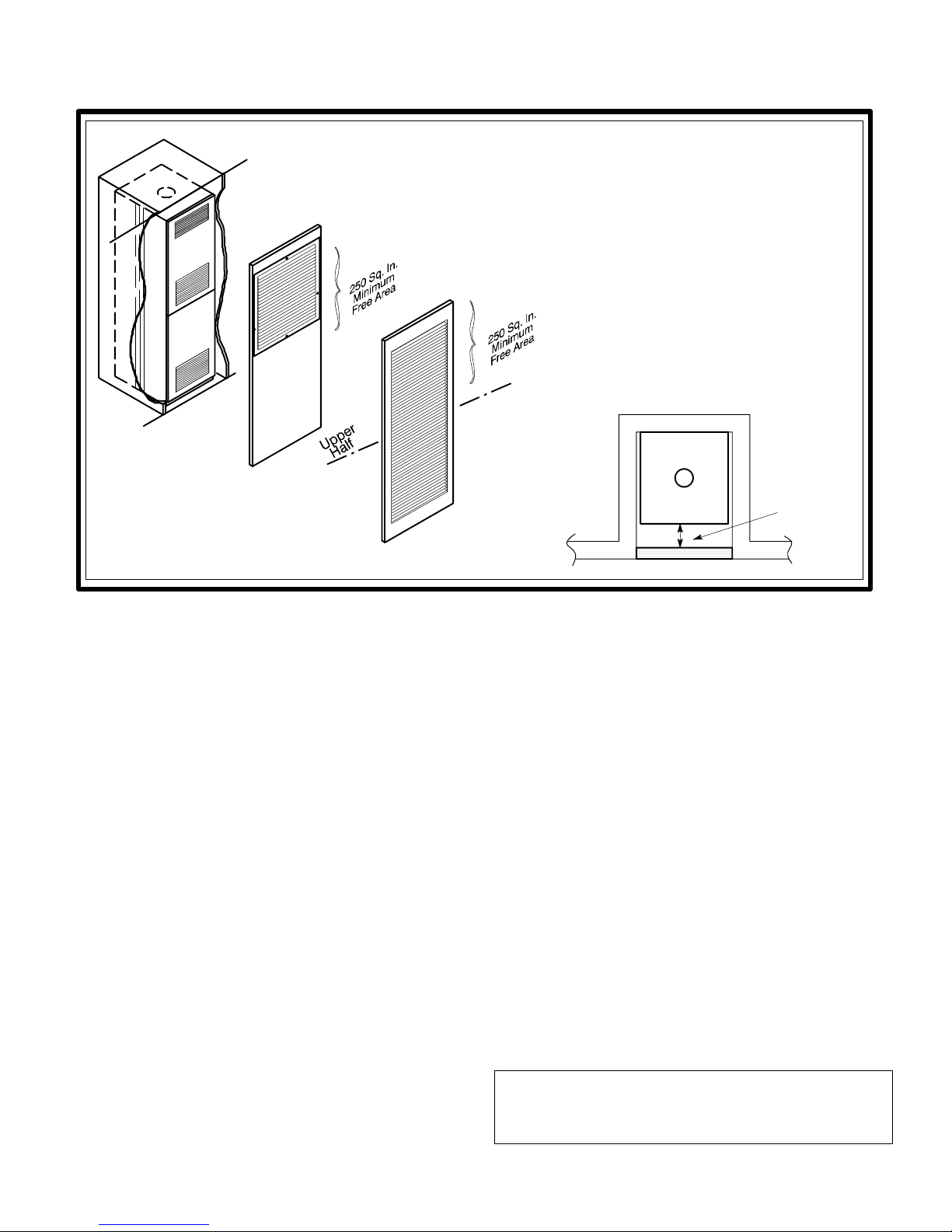
Furnace to Closet Door Clearance —
Greater than 6 Inches
The closet door MUST have a minimum of 250
Square Inches of free area in the upper half of the
door .
If the opening for return air is locatedin the sidewall and below the top of the furnace casing:
a. total side return must equal or exceed
350 sq. in. free area
b. 6” min. clearance must be provided on
thesidewherethereturnislocated
c. 6” min. clearance must be
maintained in front of the furnace.
CLOSET
FURNACE
Return Air Closet Door Part No.
7900--- 8881 — Almond
7900--- 7771/C — White
Figure 3 — Closet to Door Clearance — 6” or greater
Additional Requirements
Additional requirements for floor and ceiling return system
for closet installed sealed combustion heating appliance
are given in the next paragraph.
Floor or Ceiling Return Air System
Floor or ceiling return air system for closet installed direct
vent forced air heating appliance.
Listed in the next paragraph are the conditions to be met by
Mobile Home Manufacturers to have U.L. acceptance of
in--- floor or ceiling return air systems of closet installed direct vent forced air heating appliances for Mobile Homes to
be sold in the United States.
A. The return---air opening into the closet, regardless of
location, is to be sized not less than specified on the
appliance’s rating plate.
B. If the return---air opening is located in the floor of the
closet (versus the vertical front or side wall), the opening is to be provided with means to prevent its inadvertent closure by a flat object placed over the opening.
C. The cross---sectional area of the return duct system
(when located in the floor or ceiling of the mobile home)
leading into the closet is to be not less than that of the
opening specified on the appliance’s rating plate.
D. The total free area of openings in the floor or ceiling reg-
isters serving t he return ---air duct system is to be not
less than 150% of the size of the opening specified on
6” or greater —
Closet to Door
Clearance
DOOR
the appliance’s rating plate. At least one such register
is to be located where likelihood of its being covered by
carpeting, boxes, and other objects is minimized.
E. Materials located in the return duct system have a flame
spread classification of 200 or less.
F. N o n --- c o m b u s t i b l e p a n s h a v i n g o n e --- i n c h u p t u r n e d
flanges are located beneath openings in the floor return duct system.
G. Wiring materials located in the return duct system con -
form to Article 300 --- 22 (b&c) of the National Electric
Code (ANSI C1 / NFPA---70).
H. Gas piping is not run in or through the return duct sys-
tem.
I. The negative pressure in the closet as determined by
test with the air --- circulating fan operating at high heating speed and the closet door closed is to be not more
negative than minus 0.05---inch water column.
J. For floor return systems, the mobile home manufacturer
or installer shall affix a prominent marking on or near
the appliance where it is easily read when the closet
door is open. The marking shall read:
WARNING
HAZARD OF ASPHYXIATION
DO NOT COVER OR RESTRICT FLOOR OPENING
or equivalent.
8
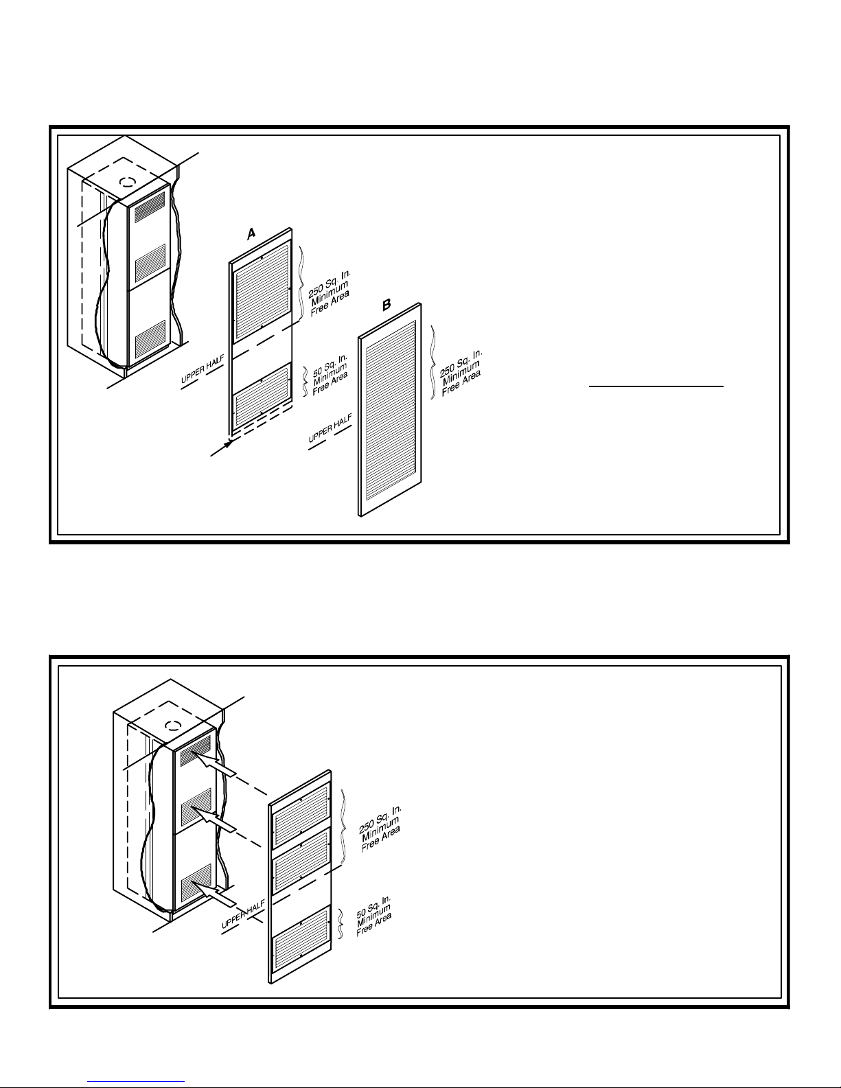
SPECIAL CLOSET INSTALLATIONS
Furnace to Closet Door Clearance — Greater than 1 Inch and Less than 6 Inches
Clearance — Greater than 1 Inch and
Less than 6 Inches
A. The closet door MUST have a minimum
of 250 Square Inches of free area in the
upper half of the door and a minimum of
50 Square Inches of free area in the lower area of the door.
The lower closet door grille may be
omitted if an undercut of 2 1/2 Inches is
provided in the door.
B. A fully louvered closet door MUST have
a minimum of 250 Square Inches of free
areaintheupperhalfofthedoor
.
As an option to the lower grill,
an undercut of 2 1/2” will provide
50 Sq. In. of free area.
Figure 4 — Furnace to Closet Door Clearance—1” to 6”
Furnace to Closet Door Clearance — Less than 1 Inch
Clearance — Less than 1”
The closet door MUST have three return air
grilles. The total free area of the two upper grilles
must be a minimum of 250 Square Inches. The
total free area of the lower grille MUST be a
minimum of 50 Sq. In.
Figure 5 — Furnace to Closet Door Clearance—Less than 1”
NOTE: Each grille MUST BE ALIGNED directly
opposite the corresponding return air grille of
the furnace door.
9
 Loading...