

Page 1
DIMENSIONAL DADIMENSIONAL DA
DIMENSIONAL DA
DIMENSIONAL DADIMENSIONAL DA
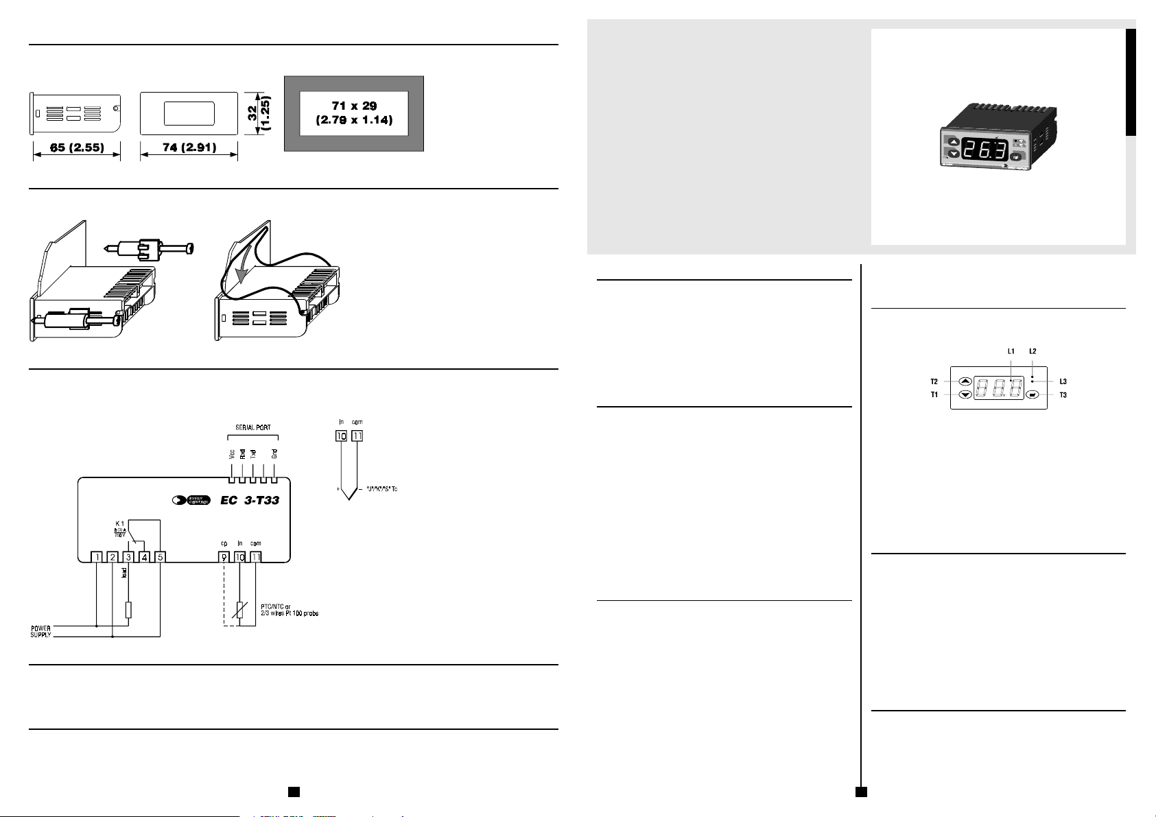
OVERALL DIMENSIONS AND PANEL CUTOUT
The dimensions are expressed in millimetres and inches (third-scale drawing).
TT
AA
T
A
TT
AA
EC 3-T33EC 3-T33
EC 3-T33
EC 3-T33EC 3-T33
ON-OFF single output digital thermoregulator supplied from main voltage
ENGLISH
ds3ve.wmf
INSTINST
ALLAALLA
ALLA
ALLAALLA
TIONTION
TION
TIONTION
TT
T
TT
Fig. 4
ms3vv.wmf
AA
A
AA
ms3vm.wmf
4
Fig. 5
c3-t33e.wmf
INST
INSTINST
WITH THE FIXING SYSTEMS SUGGESTED BY THE BUILDER
Panel mounting, with the equipped screw (Fig. 4) or spring brackets (Fig. 5) (third-scale drawing).
ELECTRICAL CONNECTIONELECTRICAL CONNECTION
ELECTRICAL CONNECTION
ELECTRICAL CONNECTIONELECTRICAL CONNECTION
CONNECTIONS TO DERIVE
Instance of typical application.
BUILDER DABUILDER DA
BUILDER DA
BUILDER DABUILDER DA
EVERY CONTROL S.r.l.
Via Mezzaterra 6, 32036 Sedico Belluno ITALY
Phone 0039/0437852468 (a.r.) Fax 0039/043783648
Internet addresses
e-mail: [email protected]
http://www.everycontrol.it
TO BE CAREFUL
This publication exclusively belongs to EVERY CONTROL and shall not be reproduced and distributed if not expressly authorized by the same EVERY CONTROL.
EVERY CONTROL does not assume any responsibility in order to the characteristics, to the technical data and to the possible mistakes related herein or deriving from the use of the same.
EVERY CONTROL can not be considered responsible for damages caused from the inobservance of the additional informations.
EVERY CONTROL reserves the right to make any modification without prior notice and at any time without prejudice the basic functioning and safety characteristics.
Fig. 3
Fig. 6
Operating instructions
Release 1/00 of February the sixteenth 2000
Code EC 3-T33 DOC E003
File 3t33e.p65
IMPORTANT:
The use of this new instrument is easy; but for safety reasons, it is
important read these instructions carefully before the installation or
before the use and follow all additional informations.
It is very important keep these instructions with the instrument for future
consultations.
GENERAL INFORMAGENERAL INFORMA
GENERAL INFORMA
GENERAL INFORMAGENERAL INFORMA
WHAT IS THE USE
EC 3-T33 is an ON-OFF single output digital thermoregulator able to cover a temperature range
from -99 to +999 °C (-99 to +999 °F); the instrument can be supplied from main voltage (230
Vac) with a very low power consumption (1 VA).
In factory the instrument gets preset to accept at the measure input PTC/NTC probes or “J”/
”K”/”S” thermocouples or 2/3 wires Pt 100 probes.
Some parameters permit to set the thermoregulator to display the temperature in Fahrenheit or
Celsius degrees, for “cooling” or “heating” functioning, to protect the connected load against
overloads due to several starts repeated in a short time, to signal working conditions outside
the safety limits.
EC 3-T33 is available in the 74 x 32 mm (2.91 x 1.25 in.) case and it is studied for panel
mounting with the equipped screw or spring brackets.
GETTING STGETTING ST
GETTING ST
GETTING STGETTING ST
INSTALLATION
EC 3-T33 was studied for panel mounting, panel cutout 71 x 29 mm (2.79 x 1.14 in.), with the
equipped screw or spring brackets (the overall dimensions and the panel cutout are related in
Fig. 3, the fixing systems suggested by the builder are related respectively in Fig. 4 and in Fig.
5).
ADDITIONAL INFORMATIONS
- the panel thickness must be included from 1 to 5 mm (0.04 to 0.19 in.)
- verify if the using conditions (ambient temperature, humidity, etc.) are within the
limits indicated by the builder (see the chapter TECHNICAL DATA)
- install the instrument in a location with a suitable ventilation, to avoid the internal
overheating of the instrument
- do not install the instrument near surfaces that can to obstruct the air-grating (carpets, covers, etc.), heating sources (radiators, hot air ducts, etc.), locations subject to direct sunlight, rain, humidity, excessive dust, mechanical vibrations or
bumps, devices with strong magnetos (microwave ovens, big speakers, etc.)
- according with the safety norms, the protection against possible contacts with
electrical parts and parts protected with functional insulation only must be ensured
through a correct installation procedure of the instrument; all parts that ensure the
protection must be fixed so that they can not be removed if not with a tool
- if not differently specified at the time of order, the instrument will be equipped with
screw brackets.
ELECTRICAL CONNECTION
EC 3-T33 is provided with two screw terminal blocks for cables up to 2.5 mm² (0.38 in.², for
the connection to the power supply, measure input and output) and it is provided with one five
poles single line male connector (for the connection to the CLONE configurer/cloner and RICS
supervision systems), located on the instrument back panel (the connections to derive are
related in Fig. 6 and they are checkable on the polyester label stuck on the instrument case).
ADDITIONAL INFORMATIONS
- if the instrument is brought from a cold to a warm location, the humidity may condense inside the instrument; wait about an hour before supply the instrument
- verify if the operating power supply voltage, electrical frequency and power of the
instrument correspond to the local power supply (see the chapter TECHNICAL DATA)
- do not supply more instruments with the same transformer
- if the instrument is installed on a vehicle, its power supply must be derived directly
from the battery of the vehicle
- give the instrument a protection able to limit the current absorbed in case of failure
- the instrument remains connected to the local power supply as long as the terminals 1 and 2 are derived to the local power supply, even if the instrument is apparently turned off
- give the probe a protection able to insulate it against possible contacts with metal
parts or use insulated probes
- give the output a protection able to protect it against short circuit and overload -
ARAR
AR
ARAR
TEDTED
TED
TEDTED
TIONSTIONS
TIONS
TIONSTIONS
do not try to repair the instrument; for the repairs apply to highly qualified staff
- if you have any questions or problems concerning the instrument please consult
Every Control (see the chapter BUILDER DATA).
USEUSE
USE
USEUSE
PRELIMINARY INFORMATIONS
After derived the connections related in Fig. 6, during the normal functioning the instrument
displays the temperature read by the probe.
If an alarm should be active the instrument displays the alarm code flashing and the buzzer
utters an intermittent beep as long as the cause that has given it does not disappear (see the
chapter SIGNALS AND ALARMS); pressure on the key T1 during an alarm permits to silence
the buzzer.
EC 3-T33 is provided with one working setpoint and with some configuration parameters that
get stored in a non volatile memory and that permit to set the instrument according with one’s
requirements (see the chapter CONFIGURABILITY).
The output K 1 is associated to the working setpoint, it remains activated continuously as long
as the temperature read by the probe reaches the working setpoint and when it rises above (if
the output was set for “cooling” functioning) or it falls below (if the output was set for “heating”
functioning) the working setpoint of the hysteresis value (differential) the output gets reactivated.
ADDITIONAL INFORMATIONS
- during the normal functioning the LED L2 or L3 turning ON to indicate the unit of
measure of the temperature read by the probe.
WORKING SETPOINT SETTING (WORKING TEMPERATURE)
To modify the working setpoint value keep pushed the key T3 (the instrument displays the
actual value) and at the same time push and release over and over the key T1 or T2 as long as
the instrument displays the desired value (keeping pushed the key T1 or T2 the value gets
decreased or increased more quickly): after the modification release the key T3 last; during the
pressure of the key T3 the LED L1 flashes quickly to indicate that a working setpoint setting
procedure is running (to the release of the key T3 the instrument automatically turns out from
the working setpoint setting procedure).
ADDITIONAL INFORMATIONS
- for the whole period of a corrupted memory data alarm the access to the working
setpoint setting procedure is refused
- the working setpoint is programmable within the limits established with the parameters rA1 and rA2
- if the parameter rA5 has value 1 the working setpoint can not be modified as long as
the parameter rA5 gets set to 0
- the working setpoint value gets stored in a non volatile memory even if a lack of
power supply happens.
CONFIGURATION PARAMETERS SETTING
Configuration parameters are arranged on two levels, to protect the most tricky settings against
undesirable violations and they are arranged in families that can be recognized through the
initial letter of the label.
To gain access to the first level keep pushed at the same time for four seconds at least the keys
T1 and T2 (passed four seconds the instrument displays the label PA).
To select a parameter of the first level push and release over and over the key T1 or T2 as long
as the instrument displays the label of the desired parameter.
To modify the parameter value keep pushed the key T3 (the instrument displays the actual
1
Fig. 1
f3-t33.wmf
Fig. 2
iu3t33.wmf
Page 2

value) and at the same time push and release over and over the key T1 or T2 as long as the
instrument displays the desired value (keeping pushed the key T1 or T2 the value gets decreased or increased more quickly); after the modification release the key T3 last (to the release
of the key T3 the instrument displays the label of the parameter again).
To gain access to the second level enter inside the first level and select the label PA.
Keep pushed the key T3 (the instrument displays the actual value) and at the same time push
and release over and over the key T1 or T2 as long as the instrument displays -19 (keeping
pushed the key T1 or T2 the value gets decreased or increased more quickly): after the modification release the key T3 last (to the release of the key T3 the instrument displays the label PA
again); keep pushed at the same time for four seconds at least the keys T1 and T2 (passed four
seconds the instrument displays the first parameter of the second level).
To select a parameter of the second level push and release over and over the key T1 or T2 as
long as the instrument displays the label of the desired parameter.
To modify the parameter value keep pushed the key T3 (the instrument displays the actual
value) and at the same time push and release over and over the key T1 or T2 as long as the
instrument displays the desired value (keeping pushed the key T1 or T2 the value gets decreased or increased more quickly); after the modification release the key T3 last (to the release
of the key T3 the instrument displays the label of the parameter again).
To turn out from the configuration parameters setting procedure keep pushed at the same time
for four seconds at least the keys T1 and T2 or do not operate with the keys for sixty seconds at
least (time-out exit).
ADDITIONAL INFORMATIONS
- for the whole period of a corrupted memory data alarm the access to the configuration parameters setting procedure is refused
- the modification of a parameter value which unit of measure is the hour or the
minute or the second has not immediate effect; to obtain this effect it must not be
executed during the course of the value
- the configuration parameters values get stored in a non volatile memory even if a
lack of power supply happens.
CONFIGURABILITYCONFIGURABILITY
CONFIGURABILITY
CONFIGURABILITYCONFIGURABILITY
WORKING SETPOINT
LABELMIN. MAX. U.M. ST. WORKING SETPOINT
rA1 rA2 (*) 0.0 working setpoint
It establishes the temperature associated to the output K 1.
CONFIGURATION PARAMETERS
LABELMIN. MAX. U.M. ST. PASSWORD
PA -90 10 0 --- 0 password (§)
It is the password that permits to gain access to the second level.
LABELMIN. MAX. U.M. ST. MEASURE INPUT
/ 0 01 21 --- (**) kind of probe
It establishes the kind of probe that the instrument must recognize to its measure input, as
indicated:
01 = PTC probe
03 = NTC probe
10 = “J” thermocouple
11 = “K” thermocouple
12 = “S” thermocouple
20 = 3 wires Pt 100 probe
21 = 2 wires Pt 100 probe.
/ 1 -25 +25.0 (*) 0.0 calibration (§)
It establishes a threshold to add algebraically to the signal coming from the measure input (for
instance to correct the signal).
/ 2 0 6 --- 3 digital filter
It establishes a time constant to apply to the signal coming from the measure input, as indicated:
0 = 0 sec. 1 = 0.4 sec.
2 = 1.2 sec. 3 = 2.8 sec.
4 = 6.0 sec. 5 = 12.4 sec.
6 = 25.2 sec.
/ 5 0 1 --- 1 decimal point
It establishes the resolution with which the temperature gets displayed, as indicated:
0 = the temperature gets displayed with the resolution of the unit of measure
1 = the temperature gets displayed with the resolution of 1/10 of the unit of measure.
/ 8 0 1 --- 1 unit of measure
It establishes the unit of measure with which the temperature gets displayed, as indicated:
0 = the unit of measure is the Fahrenheit degree
1 = the unit of measure is the Celsius degree.
LABELMIN. MAX. U.M. ST. ON-OFF TEMPERATURE REGULATOR ASSOCIATED TO
rA0 -99 +99.9 (*) -0.2 hysteresis (differential) (§)
It establishes the hysteresis (differential) relative to the working setpoint.
rA1 -99 +999 (*) (**) minimum working setpoint programmable
It establishes the minimum working setpoint programmable; the instrument automatically verifies if the value established with the parameter rA1 is below the maximum working setpoint
programmable established with the parameter rA2.
rA2 -99 +999 (*) (**) maximum working setpoint programmable
It establishes the maximum working setpoint programmable; the instrument automatically verifies if the value established with the parameter rA2 is above the minimum working setpoint
programmable established with the parameter rA1.
rA3 0 1 --- 1 “cooling” or “heating” functioning
It establishes the output functioning, as indicated:
0 = “cooling” functioning
1 = “heating” functioning.
THE WORKING SETPOINT AND TO THE OUTPUT K 1
rA4 0 1 --- 0 kind of hysteresis (kind of differential)
It establishes the kind of hysteresis (kind of differential), as indicated:
0 = asymmetrical
1 = symmetrical.
rA5 0 1 --- 0 locking of the working setpoint modification
It establishes if to prevent the modification of the working setpoint, as indicated:
0 = the working setpoint can be modified
1 = the working setpoint can not be modified as long as the parameter rA5 gets set to 0.
LABELMIN. MAX. U.M. ST. OUTPUT K 1 PROTECTION
CA0 0 999 sec. 0 disabling time to the output activation from the instru-
It establishes the time that disables the output activation from the moment of the instrument
start.
CA1 0 999 sec. 0 disabling time to the output activation from the previ-
It establishes the time that disables the output activation from the moment of the previous
output activation.
CA2 0 999 sec. 0 disabling time to the output activation from the previ-
It establishes the time that disables the output activation from the moment of the previous
output deactivation.
CA3 0 1 --- 0 output status during a probe failure alarm
It establishes the status to which the output gets forced during a probe failure alarm, as indicated:
0 = during a probe failure alarm the output gets forced to the status OFF
1 = during a probe failure alarm the output gets forced to the status ON.
CA4 0 1 --- 0 disabling time to the output activation and deactivation
It establishes if to disable the output activation and deactivation for a fixed time, as indicated:
0 = inactive
1 = the output activation and deactivation get disabled for 3 sec.
LABELMIN. MAX. U.M. ST. TEMPERATURE ALARM REGULATOR ASSOCIATED TO
AA0 +0.1 +999 (*) +0.1 hysteresis (differential)
It establishes the hysteresis (differential) relative to the parameter AA1.
AA1 -99 +999 (*) 0.0 alarm setpoint
It establishes the temperature to which the temperature alarm gets activated according with the
modality established with the parameter AA4.
AA3 0 999 min. 0 disabling time to the alarm activation from the instru-
It establishes the time that disables the temperature alarm activation from the moment of the
instrument start.
AA4 1 7 --- 1 kind of alarm
It establishes the kind of temperature alarm that the instrument must manage, as indicated:
1 = the temperature alarm never gets activated
2 = absolute lower temperature alarm
3 = absolute upper temperature alarm
4 = lower temperature alarm relative to the working setpoint
5 = upper temperature alarm relative to the working setpoint
6 = lower temperature alarm relative to the working setpoint with automatic
recomputation and reenabling
7 = upper temperature alarm relative to the working setpoint with automatic
recomputation and reenabling.
LABELMIN. MAX. U.M. ST. TEMPERATURE ALARM REGULATOR ASSOCIATED TO
Ab0 +0.1 +999 (*) +0.1 hysteresis (differential)
It has the same significance of the parameter AA0.
Ab1 -99 +999 (*) 0.0 alarm setpoint
It has the same significance of the parameter AA1.
Ab3 0 999 min. 0 disabling time to the alarm activation from the instru-
It has the same significance of the parameter AA3.
Ab4 1 7 --- 1 kind of alarm
It has the same significance of the parameter AA4.
LABELMIN. MAX. U.M. ST. CONNECTION IN A SERIAL NETWORK WITH EVCOBUS
L 1 1 15 --- 1 instrument address
It establishes the address to which the instrument (slave) answers when it is connected to a
serial network with EVCOBUS protocol communication managed from a master (for instance a
Personal Computer).
L 2 0 7 --- 0 instrument group
It establishes the group to which the instrument (slave) answers when it is connected to a
serial network with EVCOBUS protocol communication managed from a master (for instance a
Personal Computer).
L 3 7 240 sec. 30 time-out link
It establishes for which time interval the instrument must store a connection to a serial network
with EVCOBUS protocol communication from the moment in which an interruption of the
connection happens.
L 4 0 3 --- 1 baud rate
It establishes the speed with which the data get transmitted in a serial network with EVCOBUS
protocol communication, as indicated:
0 = 1,200 baud
1 = 2,400 baud
2 = 4,800 baud
3 = 9,600 baud.
2 3
ment start
ous activation
ous deactivation
THE FIRST TEMPERATURE ALARM
ment start
THE SECOND TEMPERATURE ALARM
ment start
PROTOCOL COMMUNICATION
ADDITIONAL INFORMATIONS
- the symbol (*) indicates that the unit of measure depends from the parameter / 8
- the symbol (§) indicates that the parameter is of the first level
- the symbol (**) indicates that the value depends from the measure input presetting requested
- if the instrument is preset to accept at the measure input “J”/”K”/”S” thermocouples the parameter / 5 does not exist
- if the parameter / 8 has value 0 the parameter / 5 does not exist.
SIGNALS AND ALARMSSIGNALS AND ALARMS
SIGNALS AND ALARMS
SIGNALS AND ALARMSSIGNALS AND ALARMS
SIGNALS
If the LED L1 is turned ON it means that the output K 1 is activated.
If the LED L1 flashes it means that a count of a disabling time to the output K 1 activation is
running (see the parameters CA0, CA1, CA2 and CA4).
If the LED L2 is turned ON it means that the unit of measure of the displayed quantity is the
Fahrenheit degree.
If the LED L3 is turned ON it means that the unit of measure of the displayed quantity is the
Celsius degree.
If the instrument displays the indication “---” it means that the working setpoint can not be
modified (see the parameters rA5).
ALARMS
If the instrument displays the indication “E2” flashing and the buzzer utters an intermittent
beep (corrupted memory data alarm) it means that there is a corruption of the configuration
data in the memory (turn OFF and turn ON again the instrument: if to the turning ON again the
alarm does not disappear the instrument must be replaced); during this alarm the access to the
working setpoint setting and the configuration parameters setting procedures is refused and
the output K 1 gets forced to the status OFF.
If the instrument displays the indication “E0” flashing and the buzzer utters an intermittent
beep (probe failure alarm) it means that: the kind of connected probe is not proper (see the
parameter / 0), the probe is faulty (verify the probe integrity), there is a mistake in the instrument-probe connection (verify the instrument-probe connection integrity), the temperature
read by the probe is outside the limits permitted by the probe in use (verify that the temperature near the probe be inside the limits permitted by the probe); during this alarm the output
K 1 gets forced to the status established with the parameter CA3.
If the instrument displays the indication “E0C” flashing and the buzzer utters an intermittent
beep (cold junction/third wire failure alarm) it means that, if the instrument is preset to
accept at the measure input “J”/”K”/”S” thermocouples there is a mistake in the cold junction
adjustment circuit (the instrument must be replaced), if the instrument is preset to accept at
the measure input 2/3 wires Pt 100 probes and it is set to recognize to its measure input 3
wires Pt 100 probes the third wire of the probe is not connected (verify the instrument-probe
connection integrity); during this alarm the output K 1 gets forced to the status established
with the parameter CA3.
If the instrument displays the indication “AL1” flashing alternated to the temperature read by
the probe and the buzzer utters an intermittent beep (first temperature alarm) it means that
the temperature read by the probe is outside the limit established with the parameter AA1 (see
the parameters AA0, AA1 and AA4); inactive.
If the instrument displays the indication “AL2” flashing alternated to the temperature read by
the probe and the buzzer utters an intermittent beep (second temperature alarm) it means
that the temperature read by the probe is outside the limit established with the parameter Ab1
(see the parameters Ab0, Ab1 and Ab4); inactive.
If the instrument displays the indication “999” flashing (end of scale display) it means that
the temperature read by the probe is outside the working range permitted by the instrument
(verify that the temperature near the probe be inside the limits permitted by the instrument);
inactive.
ADDITIONAL INFORMATIONS
- the alarm codes are related in order of precedence.
TECHNICAL DATECHNICAL DA
TECHNICAL DA
TECHNICAL DATECHNICAL DA
TECHNICAL DATA
Case: plastic black (PC-ABS), self-extinguishing.
Size: 74 x 32 x 65 mm (2.91 x 1.25 x 2.55 in.).
Installation: panel mounting, panel cutout 71 x 29 mm (2.79 x 1.14
Type of protection: IP 54.
Connections: screw terminal blocks with pitch 5 mm (0.19 in., power
Ambient temperature: from 0 to +60 °C (+32 to +140 °F, 10 ... 90 % of not con-
Power supply: 230 Vac or 115 Vac, 50/60 Hz, 1 VA.
Insulation class: II.
Alarm buzzer: incorporated.
Measure inputs: 1 configurable, hardware depending, for PTC/NTC probes
Working range: from -50 to +150 °C (-58 to +302 °F) for PTC probe, from
Setting range: from -99 to +999 °C (-99 to +999 °F).
Resolution: 1 °F with unit of measure in Fahrenheit, configurable for
TT
AA
T
A
TT
AA
in.), with the equipped screw or spring brackets.
supply, measure input and output) for cables up to 2.5 mm²
(0.38 in.²), five poles single line male connector with pitch
5.08 mm (0.2 in., serial port).
densing relative humidity).
or “J”/”K”/”S” thermocouples or 2/3 wires Pt 100 probes.
-40 to +110 °C (-40 to +230 °F) for NTC probe, from -99
to +700 °C (-99 to +999 °F) for “J” thermocouple, from
-99 to +999 °C (-99 to +999 °F) for “K” thermocouple,
from -99 to +999 °C (-99 to +999 °F) for “S” thermocouple, from -99 to +600 °C (-99 to +999 °F) for 2/3 wires Pt
100 probes.
0.1 (except the instruments preset to accept at the meas-
ure input “J”/”K”/”S” thermocouples) or 1 °C with unit of
Display: 3-digit display 12.5 mm (0.49 in.) high red LED display
Outputs: one change-over contact 8 (3) A @ 250 Vac relay for regu-
Serial port: TTL with EVCOBUS protocol communication, for the con-
HOW TO ORDERHOW TO ORDER
HOW TO ORDER
HOW TO ORDERHOW TO ORDER
CODING SYSTEM
Instrument name: EC 3-T33.
Desired measure input: P (for PTC/NTC probes),
Desired power supply: 220 (230 Vac),
Options: custom configuration.
measure in Celsius.
with automatic decimal point and minus sign, output status indicator, unit of measure of the displayed quantity indicators.
lation load management.
nection to the CLONE configurer/cloner and RICS supervision systems.
J (for “J”/”K”/”S” thermocouples),
C (for 2/3 wires Pt 100 probes).
115 (115 Vac).
 Loading...