

Page 1
EVCO S.p.A. | Code 104D2EA104 | Pag. 1 di 2| GL 10/13 | version 1.0
DADO series
Internet / MODBUS Gateway
EN ENGLISH
DADO communicates with the CloudEvolution internet portal via Ethernet using the existing network infrastructure (on
EVD2ETHB30), Ethernet or GPRS (on EVD2ETHG30) and Ethernet or WiFi (on EVD2ETHW30).
The communication mechanism has a low data volume and it has been designed to be as much rewall-endly as possible.
Static IP address not requested.
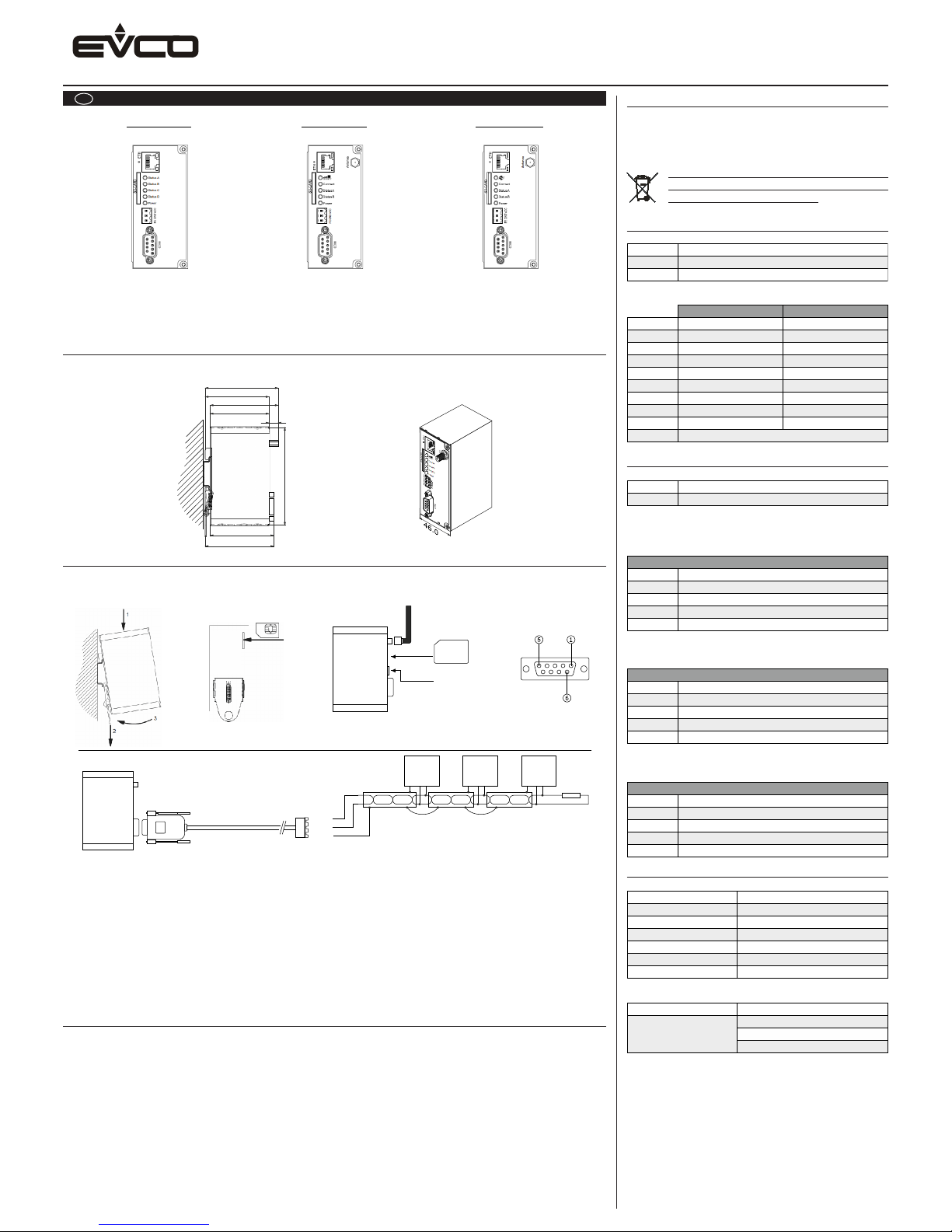
DIMENSIONS
Dimensions
The dimensions are expressed in mm.
77.6
68.1
72.6
63.1
9.5
130.0
68.5
73.0
INSTALLATION
Installation
Device may only be put into service and operated by qualied personnel only.
The device is designed for an installation on a grounded 35 mm DIN Rail in dry rooms.
• After installation the housing of the device is connected with functional earth.
• The power supply must be a grounded circuit (PELV) and it must be a limited power source according to
EN60950-1 cap 2.5 or the device must be provided with an antisurge fuse of 2 A.
• Insert the SIM card in the device’s rear before the installation on the DIN rail, The device must be switched off (only on
EVD2ETHG30). It is recommended to remove the SIM card PIN before use in the device.
• Never use the device in areas where the operation of wireless equipment is prohibited. The location for the antenna
must guarantee the recommended radiological limits (be at least 20 cm from persons and other antennas). When the
antenna is installed outdoors the lightning protection standard VDE V0185 must be complied with. The EMC lightning
protection zone concept must be observed. The device must be switched off during work on the antenna. It can not be
guaranteed, that there will not be any harmful interference for other devices. In case of interferences install the device
or the antenna in another location (only for EVD2ETHG30 and EVD2ETHW30).
GETTING STARTED
Getting started
Wire the device according to the technical data.
Get the “Installation manual” at www.evco.it/eng/products/monitoring/clouevolution.html and follow instructions.
EVD2ETHB30
Ethernet
EVD2ETHG30
Ethernet / GPRS
EVD2ETHW30
Ethernet / WiFi
RS485
+
-
GND
Device
1
Device
2
Device
3
(db9 to therminal
block adapter)
120 ohm
(only on EVD2ETHG30)
1= Y (+)
5= GND
6= Z (-)
RS485
24 VDC
SD card
IMPORTANT
Read this document thoroughly before installation and before
use of the device and follow all recommendations; keep this
document with the device for future consultation.
Only use the device in the way described in this document.
The device must be disposed of in compliance
with local standards regarding the collection of
electric and electronic equipment.
1 PIN ASSIGNMENT
1.1 Power supply
1.2 Serial interface
2 LEDs
2.1 Ethernet interface
2.2 LEDs meaning
The following chart illustrate the LEDs meaning on EVD2ETHB30 (Ethernet):
The following chart illustrate the LEDs meaning on EVD2ETHG30 (Ethernet / GPRS):
The following chart illustrate the LEDs meaning on EVD2ETHW30 (Ethernet WiFi):
3 GENERAL DATA
3.1 General data
3.2 Electrical data
3.2 Scope of supply
• EVD2ETHB30 or EVD2ETHG30 or EVD2ETHW30
• Start-up guide
• Connector 3-pin
• DB9 - Terminal Block Adapter
• Male 90° GPRS antenna (EVD2ETHG30)
• Male 90° WiFi antenna (EVD2ETHW30)
• EVPS02
FE
Functional earth
GND
VCC
24 VDC
Ground
Pin 1
NC
Y (+)
RS232 RS485
RxD
Pin 2
Pin 3
Pin 4
Pin 5
Pin 6
Pin 7
Pin 8
Pin 9
Housing
TxD
NC
GND
NC
RTS
CTS
NC
Connected to functional earth
NC
NC
NC
GND
Z (-)
NC
NC
NC
Green LED
Link indication
Activity indication
Yellow LED
Status A
- - -
- - -
LEDs on EVD2ETHB30
Serial communication (MODBUS)
MODBUS TCP communication
Device is powered
Status B
Status C
Status D
Power
Modem
LEDs on EVD2ETHG30
Serial communication (MODBUS)
MODBUS TCP communication
Device is powered
GSM/GPRS
Status A
Status B
Power
Modem is initialized
GPRS internet connection status
WLAN
LEDs on EVD2ETHW30
Serial communication (MODBUS)
MODBUS TCP communication
Device is powered
Connect
Status A
Status B
Power
WLAN module is initialized
WLAN connection status
Size (WxLxH)
Operating Temperature
Electrical shock
Protection rating
EMC emission
EMC immunity
Compliance
46x105x70 mm
0 bis 55 °C
Class III
IP20
IEC 61000-6-4
IEC 61000-6-2
CE, RoHS
Supply voltage
Operating Temperature
24 VDC (±15%)
<80 mA (on EVD2ETHB30)
<120 mA (on EVD2ETHG30)
<0.10 A (on EVD2ETHW30)
Page 2
EVCO S.p.A. | Code 104D2EA104 | Pag. 2 di 2| GL 10/13 | version 1.0
DADO series
Internet / MODBUS Gateway
Questo documento è di esclusiva proprietà EVCO; EVCO non si assume alcuna responsabilità in merito ai possibili errori riportati.
Il cliente (costruttore, installatore o utente nale) si assume ogni responsabilità in merito alla congurazione del dispositivo.
EVCO non può essere ritenuta responsabile per danni causati dall’inosservanza delle avvertenze.
EVCO si riserva il diritto di apportare qualsiasi modica, senza pregiudicare le caratteristiche essenziali di funzionalità e di sicurezza.
EVCO S.p.A.
Via Feltre 81, 32036 Sedico (BL) ITALIA
telefono 0437 8422 | fax 0437 83648
email [email protected] | web www.evco.it
I ITALIANO
DADO comunica con il portale internet di CloudEvolution via Ethernet utilizzando l’infrastruttura di rete esistente (con
EVD2ETHB30), via Ethernet o GPRS (con EVD2ETHG30) ed Ethernet o WiFi (con EVD2ETHW30).
Il meccanismo di comunicazione ha un basso volume di dati ed è stato progettato per essere il più rewal-endly possibile.
Non è richiesto un indirizzo IP statico.
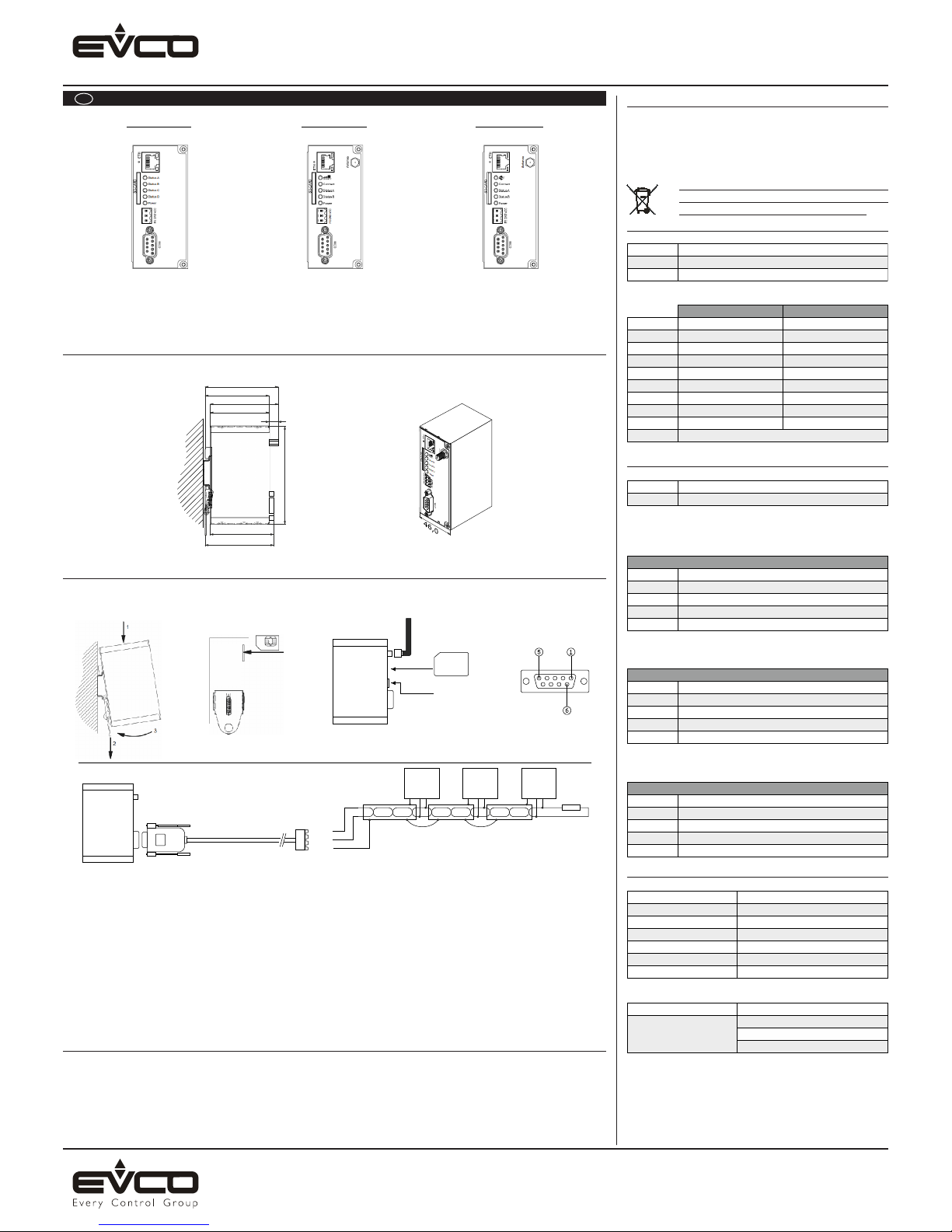
DIMENSIONI
Dimensioni
Le dimensioni sono espresse in mm.
77,6
68,1
72,6
63,1
9,5
130,0
68,5
73,0
INSTALLAZIONE
Installazione
Il dispositivo deve essere messo in servizio e gestito solo da personale qualicato.
Il dispositivo è stato progettato per l’installazione su guida DIN da 35 millimetri con messa a terra e in ambienti asciutti.
• Dopo l’installazione l’alloggiamento del dispositivo deve essere collegato con messa a terra funzionale.
• L’alimentazione deve essere un circuito dotato di messa a terra (PELV) e deve essere una fonte di alimentazione limitata
secondo
EN60950-1 cap 2.5 o il dispositivo deve essere dotato di un fusibile anti pompaggio di 2 A.
• Inserire la scheda SIM nella parte posteriore del dispositivo prima dell’installazione sulla guida DIN, il dispositivo deve
essere spento (solo su EVD2ETHG30); si consiglia di disabilitare il PIN della scheda SIM prima dell’inserimento.
• Non utilizzare il dispositivo in aree dove è proibito il funzionamento di apparecchi wireless. La posizione dell’antenna deve
garantire i limiti radiologici raccomandati (deve essere ad almeno 20 cm da persone e altre antenne). Quando l’antenna
è installata all’esterno, la protezione da fulminazione della normativa VDE V0185 deve essere rispettata. Il concetto di
zona protetta da fulmini EMC deve essere seguito. Il dispositivo deve essere spento durante il lavoro sull’antenna. Non
può essere garantita l’assenza di interferenze dannose per altri dispositivi. In caso di interferenze installare il dispositivo
o l’antenna in un altro luogo (solo per EVD2ETHG30 e EVD2ETHW30).
PER INIZIARE
Per iniziare
Collegare lo strumento seguendo i dati tecnici.
Scaricare il “manuale installazione” su www.evco.it/eng/products/monitoring/clouevolution.html e seguire le istruzioni.
EVD2ETHB30
Ethernet
EVD2ETHG30
Ethernet / GPRS
EVD2ETHW30
Ethernet / WiFi
RS485
+
-
GND
Device1Device2Device
3
(db9 to therminal
block adapter)
120 ohm
(only on EVD2ETHG30)
1= Y (+)
5= GND
6= Z (-)
RS485
24 VDC
SD card
IMPORTANTE
Leggere attentamente questo documento prima dell’installazione e prima dell’uso del dispositivo e seguire tutte le
avvertenze; conservare questo documento con il dispositivo
per consultazioni future.
Utilizzare il dispositivo solo nelle modalità descritte in questo
documento.
Il dispositivo deve essere smaltito secondo le
normative locali in merito alla raccolta delle
apparecchiature elettriche ed elettroniche.
1 ASSEGNAZIONE DEI PIN
1.1 Alimentazione
1.2 Interfaccia seriale
2 LEDs
2.1 Interfaccia ethernet
2.2 SignicatodeiLED
La seguente tabella illustra il significato dei LED su
EVD2ETHB30 (Ethernet):
La seguente tabella illustra il significato dei LED su
EVD2ETHG30 (Ethernet / GPRS):
La seguente tabella illustra il significato dei LED su
EVD2ETHW30 (Ethernet WiFi):
3 DATI GENERALI
3.1 Dati generali
3.2 Dati elettrici
3.2 Contenuto della confezione
• EVD2ETHB30 o EVD2ETHG30 o EVD2ETHW30
• Guida di start-up
• Connettore a 3-pin
• Adattatore DB9 - Morsettiera
• Antenna maschio 90° GPRS (EVD2ETHG30)
• Antenna maschio 90° WiFi (EVD2ETHW30)
FE
Functional earth
GND
VCC
24 VDC
Ground
Pin 1
NC
Y (+)
RS232 RS485
RxD
Pin 2
Pin 3
Pin 4
Pin 5
Pin 6
Pin 7
Pin 8
Pin 9
Housing
TxD
NC
GND
NC
RTS
CTS
NC
Connected to functional earth
NC
NC
NC
GND
Z (-)
NC
NC
NC
Green LED
Link indication
Activity indication
Yellow LED
Status A
- - -
- - -
LEDs on EVD2ETHB30
Serial communication (MODBUS)
MODBUS TCP communication
Device is powered
Status B
Status C
Status D
Power
Modem
LEDs on EVD2ETHG30
Serial communication (MODBUS)
MODBUS TCP communication
Device is powered
GSM/GPRS
Status A
Status B
Power
Modem is initialized
GPRS internet connection status
WLAN
LEDs on EVD2ETHW30
Serial communication (MODBUS)
MODBUS TCP communication
Device is powered
Connect
Status A
Status B
Power
WLAN module is initialized
WLAN connection status
Size (WxLxH)
Operating Temperature
Electrical shock
Protection rating
EMC emission
EMC immunity
Compliance
46x105x70 mm
0 bis 55 °C
Class III
IP20
IEC 61000-6-4
IEC 61000-6-2
CE, RoHS
Supply voltage
Operating Temperature
24 VDC (±15%)
<80 mA (on EVD2ETHB30)
<120 mA (on EVD2ETHG30)
<0.10 A (on EVD2ETHW30)
 Loading...