

Page 1

Installation Manual: EVAX 25/50/100/150/200 Voice Evacuation System
NOTICE TO THE INSTALLER
This manual provides an overview and the installation instructions for the EVAX 25/50/100/150/200 Voice Evacuation Interface System.
All terminals are power limited and should be wired in accordance with the requirements of NFPA 70 (NEC), NFPA 101 (Life Safety
Code) and NFPA 72 (National Fire Alarm Code). Failure to follow the wiring diagrams in the following pages will cause the system to not
operate as intended. For further information, refer to the control panel installation instructions.
The module shall only be installed with listed control panels. Refer to the control panel installation manual for proper system operation.
1. Description
The EVAX 25/50/100/150/200 is a self contained amplier, tone generator, digital message repeater and supervisory interface. It
is designed to be used in conjunction with a UL listed Fire Alarm Control Panel (FACP) to provide a Listed Voice Evacuation Alarm
System.
The FACP provides all initiating circuitry and a signaling circuit to the EVAX 25/50/100. The EVAX 25/50/100 provides its own internal
supervision as well as supervision for its speaker lines. Any fault is reported back to the FACP. In normal standby the supervisory circuit
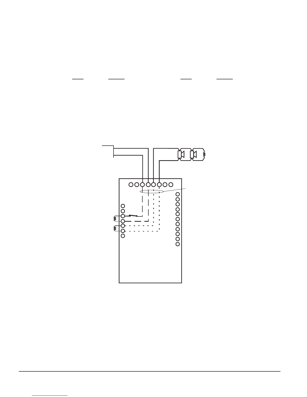
from the panel is connected to a matching EOLR. Should the EVAX 25/50/100 suffer an internal failure or should there be any fault on
the speaker line a contact would open and the FACP would report it as an open fault for that circuit.
The EVAX 25/50/100 is designed to be powered from 120 VAC at 60 Hz. The EVAX 25 will provide 25W to the speaker circuit. The
EVAX 50 will provide 50W. The EVAX 100 will provide 100W. Speakers may be 25 or 70 Vrms (jumper selected, 25V is factory set).
Note: Models may be supplied with transformers wired for 240 VAC for those regions where this is required. Please refer to Ratings
section for Primary Power differences.
MODELS: The EVX-25/50/100 are complete Voice Evacuation Modules, EVX-25E/50E/100E are complete modules with built-in tone
generators capable of operating as a stand-alone Voice Evacuation Systems with only tone and microphone amplication. They are not
equipped with power transformers or cabinets. The EVAX 25/25EM/50/50EM/100/100EM/150/150EM/200/200EM are complete Voice
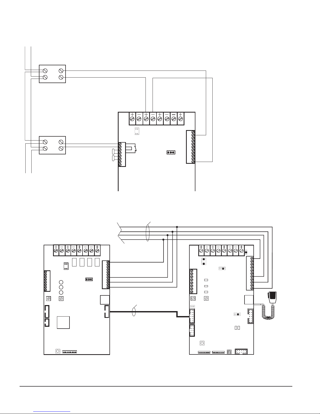
Evacuation Panels. The EVX-50E/100E are capable of operating as slave ampliers when connected to the EVX-100 which supplies
source audio to the slaves. Different Model numbers are derived from the amplier sizes used together: These multiple amplier
congurations are factory setup and pre-wired. When using any EVX-25E/50E/100E refer to installation instructions 5403672.
EVAX 150 contains one (1) EVX-100, one (1) EVX-50E and two (2) speaker circuits
EVAX 200 contains one (1) EVX-100, one (1) EVX-100E and two (2) speaker circuits
EVAX 150E contains one (1) EVX-100E, one (1) EVX-50E and two (2) speaker circuits
EVAX 200E contains two (2) EVX-100E and two (2) speaker circuits.
The EVAX 100 / 200 are tested compliant with UL 464 520 Hz Low Frequency Signal for Sleeping Areas with the following:
Potter Signal Series: FASPKR, SPKSTR Gentex Series: SSPKCLP, SSPK24WLP System Sensor Series: SPCW, SPCR, SPR and
SPW
2. Installation and Wiring
Install equipment in a clean, dry environment, avoid installation where equipment could be subjected to vibration. Remove electronic
assemblies from the enclosure prior to any drilling or punching of the enclosure. Where possible, make all cable entries from the rear or
sides. Before making any modications to the enclosure, be certain that they will not interfere with assemblies or batteries
Install equipment adjacent to FACP or FACP Annunciator to ensure proper reporting and display of system Fault conditions.
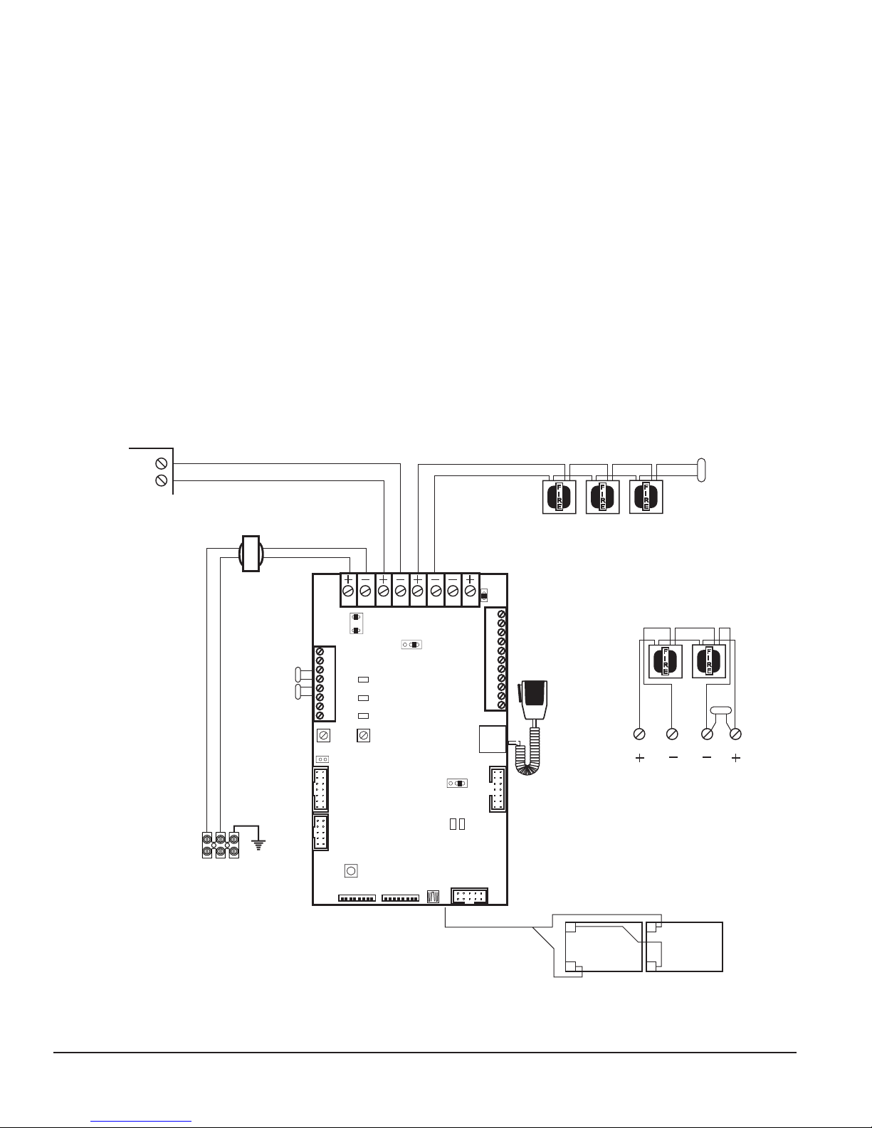
1. Connect speaker lines to TB1 - 5(+) & 6(-), observe polarity and ensure all speakers are connected likewise. For Class "A" (Style
"Z")the returns are TB1 - 7(-) & 8(+).
2. Ensure that the microphone is attached to connector P2. If Microphone is not installed ensure that switch SN1 - 8 is in the OFF
position.
3. Attach the appropriate EOLR for the FACP to TB3 - 3 & 4 and TB3 - 5 & 6. The TB3 term 5 & 6 value must be placed at the end
of the speaker line as well. You must use EOLR value as specied in the FACP Manufacturer’s installation instructions for the
indicating appliance circuit. All accessory cards such as the EVX-ZM, EVX-SL8, EVX-IL8 or EVX-OL8 must be mounted within the
same cabinet or if mounted in a separate cabinet, be in the same room with all wiring run in conduit within 20 feet.
Evax by Potter • Phone: (888) 382-9835 • www.evax.com
5403670 Rev A 12/17
PAGE 1 OF 8
Page 2

INSTALLATION MANUAL: EVAX 25/50/100/150/200
ON
4. Connect FACP signaling circuit to TB1 - 3(+) & 4(-), Alarm Polarity (alarm polarity is shown).
5. Connect 120 VAC, 60 Hz, power to the white Terminal Block on the left side of the cabinet. Terminals are Hot / Neutral /
Ground, from left to right. Pre-wired to unit and chassis on opposite side of Terminal Block. Wire colors Black / White / Green
from left to right. Max. 10 AWG
6. Once power is on to the unit, connect battery wiring harness, Red (+) / Black (-). Observe polarity. Minimum battery size is
24V 7Ah. Maximum size to house in cabinet is 12Ah, battery box required beyond 12Ah (use two (2) 12V batteries connected
in series, see typical installation diagram). If the unit does not have its own batteries and relies on an external power supply
with battery back-up, ensure that switch SN1 - 7 is in the OFF position. NOTE: Wiring for batteries is Non Power-Limited. Care
must be taken to ensure that all Power-Limited wiring maintain a minimum spacing of ¼" from any Non Power-Limited wiring.
If batteries must be located in separate enclosure, it must be in the same room with a separate conduit run for battery wiring
only.
Once all power and circuits are connected, the Green LED will remain on to indicate that the EVAX 25 / EVAX 50 / EVAX 100 is
fully operational and all circuits are nominal.
7. Terminal Designations
TB1:
TER 1 & 2 - Power Input 24-32V AC/DC (Note 1, 4)
TER 3 & 4 - FACP Signal Circuit Input - 10mA max. (Alarm Polarity shown) (Note 1, 4)
TER 5 & 6 - 25/70 Vrms Speaker Loop Style Y/Z (Class "A"/"B" start) (Note 2, 4)
TER 7 & 8 - 25/70 Vrms Speaker Loop Style Z (Class "A" return) (Note 2, 4)
TB3:
TER 1 & 2 (Note 1, 4)
Optional FACP Supervisory Circuit (See
nstallation instructions page X diagram 2 for
details (32V - 0.4A max)). Factory set for
None - J1 (Installed)
Contact Ratings: 1A @30VDC
Connect to Resistive Load, Class II Power Or
Power Limited Sources Only. Interconnected
Equipment Must be in the Same Room and
Mounted Within 20'.
TER 3 & 4
FACP Signal/Supervisory Circuit EOLR
TER 5 & 6
Matching EOLR
TB1
1
2
3
4
5
6
7
8
12 3
1
2
TB3
LED 1
YEL
LED2
GRN
LED 3
RED
J1
FAULT
NORMAL
ALARM
5678
4
J2
123
70V 25V
TER 7 (Note 1, 3, 5)
General purpose output (pulls to circuit neg
on fault condition 32V - 0.2A max). Not for
Fire Protective Signaling use.
TER 8 (Note 1, 3, 5)
Trouble input +24 VDC 5mA
NOTES
1 - Intended for connection to Listed Class
2 - Class 3 (Power Limited) sources only
2 - Power Limited
3 - Non-Supervised
4 - Supervised
5 - Terminating equipment must be installed
in same room as EVAX 25/50/100
MSG
GAIN
Switch Network Detail
P3
P5
SN1
S1
MIC
GAIN
SN2
18
P9
OFF
J3
DR
LED 5
LED 4
P8
P4
J5
11
10
9
8
7
6
5
4
3
2
1
TB2
P2
Field wiring connections:
#6-32 wire clamp screw 14-18 AWG
#8-32 wire clamp screw 12-18 AWG
Horizontal wire entry terminal 18-26 AWG
Wire gauge determined by circuit load
TB2:
TER 1 - Circuit Neg
TER 2 (NOTE 1, 3)
Aux Audio Input
(0.5V nominal)
(1VRMS - 1mA max.)
TER 3 (NOTE 1, 3, 5)
PreAmp In/Out
(600 Ohm 0dBm)
TER 4 (NOTE 1, 3, 5)
Master - Programmable
+24VDC Active
Slave - +24VDC Input
TER 5 (NOTE 1, 3, 5)
Signal Active
Master - Out / Slave - In
TER 6 (NOTE 1, 3)
Aux Audio Enable
(+24V)(32V - 5mA max.)
TER 7 (NOTE 1, 3)
Aux Signal Activate
(+24V) (32V - 5mA max.)
TER 8 (NOTE 2, 3, 5)
Common Alarm Voltage +24V
condition (0.1A)
TER 9 (NOTE 2, 3)
Common Int V+ (+24V) disconnected in
alarm condition (0.1A)
TER 10 (NOTE 2, 3)
V+ (+24V 0.1A)
TER 11 (NOTE 5)
Mic PTT (+24V 0.1A)
P3/4: 14 Pin Connector Connection to
Expander Modules
P5: 10 Pin Connector HMX Connection
P8: I2C 10 Pin Connector EVX-ZM/SL8/
IL8/OL8
Evax by Potter • Phone: (888) 382-9835 • www.evax.com
5403670 Rev A 12/17
PAGE 2 OF 8
Page 3

INSTALLATION MANUAL: EVAX 25/50/100/150/200
Factory Default Switch/Jumper Settings:
SN1 SN2
1 = OFF 25V 1 = OFF
2 = OFF 2 = ON
3 = OFF 3 = OFF Std. Evac Message
4 = OFF Normal Op 4 = OFF
5 = OFF Do Not Use 5 = OFF Do Not Use
6 = OFF No AC Fault Delay 6 = ON Message On
7 = ON Battery connected 7 = OFF
8 = ON Mic connected 8 = ON
OPTIONS:
AUX +24VDC OUTPUT - TB2-4, 8, 9 & 10
These terminals provide a max. 200 mA of regulated 24VDC power for auxiliary functions. Do not exceed 200 mA load combined
on these terminals. For connection to Listed General Signal devices only (Non-Fire Protective Signaling applications). Terminal 4
activation is programmed in the system conguration. Standard conguration is programmed for TB2-4 to go active +24VDC under
these conditions: Aux Signal Active, Aux Audio Enable and Bell Circuit Active.
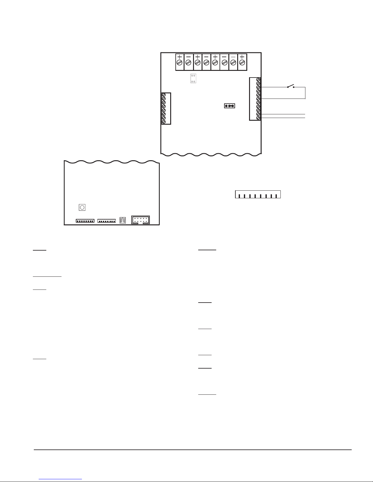
CONNECTION OF AN AUX AUDIO SOURCE - TB2-1 & 2
An aux audio source from additional paging equipment may be connected to the EVAX 25 / 50 / 100 to augment an existing paging
system. It is not intended for continuous signal input, but may be used for paging applications. For such an operation the Aux Audio
Enable input, TB2-6, must be powered from Int V+, TB2-9. This is to ensure that in the event of an alarm, the aux audio will not
override the evacuation signal. See Wiring Diagram 5 for connection detail.
Do Not Use
2 Cycles
Temporal Tone
3 Message
Repeats
J1 A/B:
1 - 2 = SHORT
J2
25 VRMS 2 - 3 = SHORT
70 VRMS 1 - 2 = SHORT
To change output voltage
Power unit down, move J2 to new
position, change SN1-1 to match.
J3
2 - 3 = SHORT R
Shorting block must be in the R position
J5
1 - 2 SHORT = Ground Fault Enable
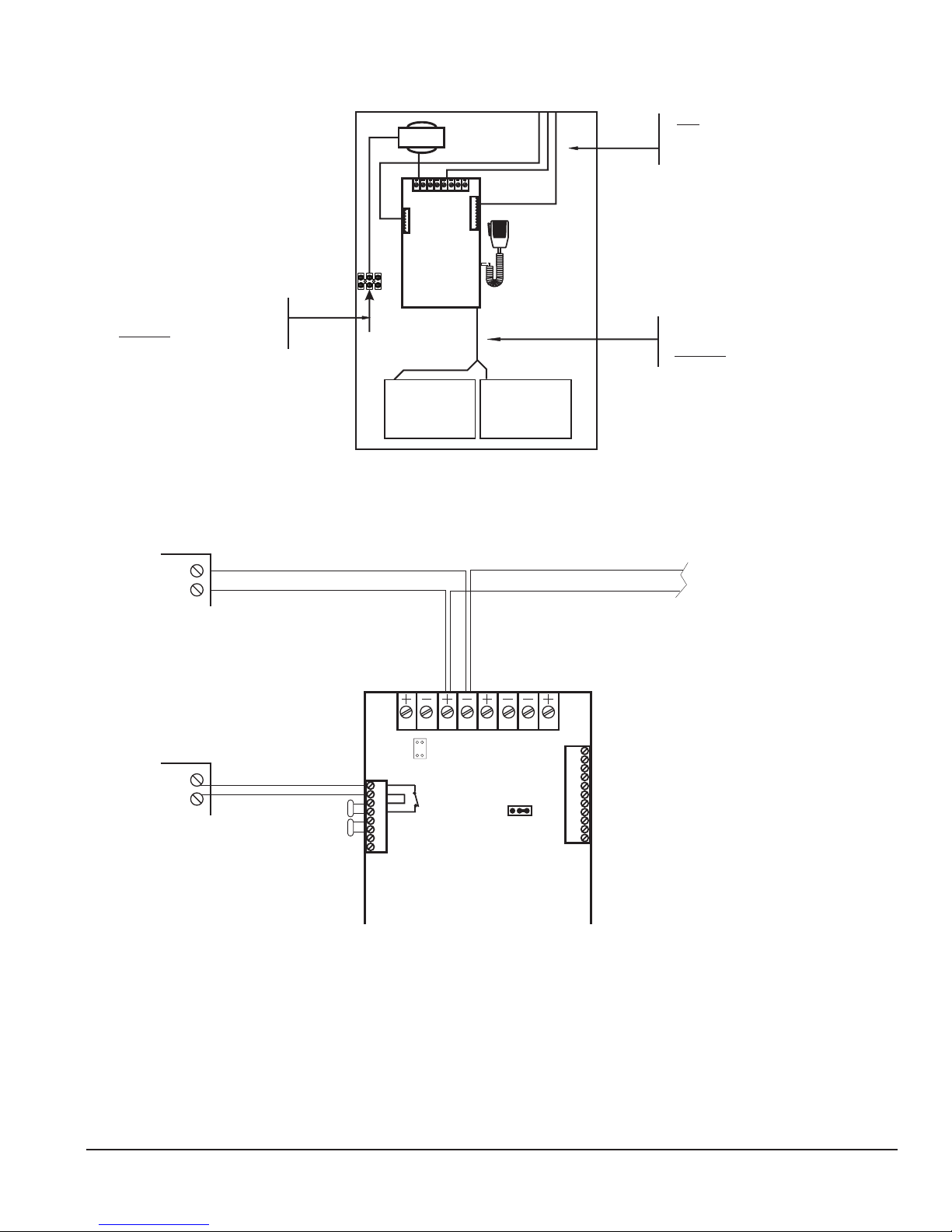
OPTIONAL SUPERVISORY CIRCUIT - TB3-1 & 2
In place of normal supervision via the signaling circuit, an alternate method may be employed using any supervisory circuit from the
FACP. Connection would be made to Terminal Block 3, Ter. 1 and 2. This would provide a normally closed connection to the EOLR
on Ter. 3 and 4. The relay contact in the circuit will open upon any trouble condition and report an open circuit trouble to the FACP.
NOTE: Jumper shorting blocks A and B must be removed from J1 if a circuit is to be connected in this manner. See Optional
Supervisory Circuit Application (Wiring Diagram 2) for connection detail.
OPERATION
In normal standby the Green LED will remain on.
In alarm condition the Red LED will remain on as long as the unit is in alarm. Green LED will modulate with the audio level.
Default Factory Alarm Sequence settings: (Alarm Tone - 2 cycles Temporal Whoop, Message On - 3 Repeats)
Alarm Tone / Digital Message plays / Alarm Tone / Digital Message plays / Alarm Tone / Digital Message plays / unit reverts to
Alarm Tone until alarm condition is cleared. If the Mic is keyed it will override both the tone and the message so a direct broadcast
may be made. If this occurs during the initial sequence the digital message will be reset and will not repeat. When the Mic is keyed
or when the message is played the Green LED will dim. The intensity of the Green LED will vary with the level of the broadcast
audio. Under a fault condition, the Yellow LED will remain on. The Green LED will ash. The number of ashes display a code
depending on the specic type of fault. When there is a fault condition the contact connecting the FACP signal circuit to the
EOLR will open indicating the fault to the panel which will provide annunciation. During a ground fault condition, Yellow LED 4 will
illuminate.
Electrical Ratings:
EVAX 25/25E EVAX 50/50E EVAX 100/100E
Primary Input Voltage 120 Vac @ 60 Hz 120 Vac @ 60 Hz 120 Vac @ 60 Hz
Primary Input Current 0.8 A @ 120 Vac 0.5 A @ 120 Vac 1.0 A @ 120 Vac
*Battery Input Current Standby 0.18 A / 1.1 A 0.15 A / 1.0 A 0.16 A / 1.1 A
Battery Input Current Alarm 1.1 A / 2.5 A 0.8 A / 1.1A 0.6 A / 2.0 A
Output power 25 Watt 50 Watt 100 Watt
Freq. Response 800 - 2800 Hz 400 - 4000 Hz 400 - 4000 Hz
Output Voltage 25/70 Vrms Selectable 25/70 Vrms Selectable 25/70 Vrms Selectable
Battery Charging Current 800mA 800mA 800mA
Minimum Battery Size 24V 7 AH 24V 7 AH 24V 7 AH
Maximum Battery Size 24V 18 AH 24V 18 AH 24V 18 AH
Battery Type is two (2) 12V Gel Cell (in Series) for all products.
For units wired with 240 VAC Transformers the following ratings apply:
Evax by Potter • Phone: (888) 382-9835 • www.evax.com
5403670 Rev A 12/17
PAGE 3 OF 8
Page 4
INSTALLATION MANUAL: EVAX 25/50/100/150/200
Red
Jumper Wire Is Provided
FIRE ALARM CONTROL PANEL
Do not loop wire around speaker terminals.
Note:
transformers wired for 240 V
those regions where this is required.
Please refer to Ratings section for
Primary Power dif
EVAX 25 / 25E EVAX 50 / 50E EVAX 100 / 100E
Primary Input Voltage 240 Vac @ 50 Hz 240 Vac @ 50 Hz 240 Vac @ 50 Hz
Primary Input Current 0.4 A @ 240 Vac 0.27 A @ 240 Vac 0.53 A @ 240 Vac
Battery Standby Operating Time: 24 - 72 Hours standby, 15 Minutes in Alarm
72 Hour standby is only recommended for EVX-100 / 100E with 24 AHr. batteries. Installer must ensure that Battery Standby current does not exceed 0.25A in
order to ensure reliable operation.
Output Protection: Power Limited, Open and Short Circuit Protected
*Battery input current measurements are determined by test conditions. Two values are shown. First value reects the unit with a full speaker load and no auxiliary load.
Second value reects the unit with a full speaker load and a full auxiliary load of 0.5A. Your actual load will vary depending on which and how many auxiliary devices,
ie...Zone Splitter, Remote Mic, Relays,...etc., are used. Insure that any current draw from an aux device is added into your nal battery calculation.
Input current measurements are determined by test conditions under UL 1711. Sine represents measurements made while the unit produces a continuous non-distorted
sine wave of 1 KHz into the rated load of 25 / 50 / 100W at rated output voltage. Alarm is the average current the unit experiences delivering an alarm signal, Temporal
Whoop, to the rated load. Standby is the current draw of the unit with all normal power on and aux., terminals fully loaded. Battery Standby is current draw from the
batteries on loss of power and otherwise normal standby.
TESTING
Per NFPA 72 Chapter 7, 100% system test is required, at a minimum, annually. Additional testing may be required by the Local
Jurisdiction.
EVAX 25/50/100 Typical Installation
SIGNAL
CIRCUIT
12-32VDC
ALARM POLARITY
Panels may be supplied with
ferences.
Field wiring connections:
#6-32 wire clamp screw 14-18 AWG
#8-32 wire clamp screw 12-18 AWG
Horizontal wire entry terminal 18-26 AWG
Wire gauge determined by circuit load
_
+
AC for
INPUT POWER
NAC Circuit Must be steady to play Voice message
Supervised - Power Limited
Supervised - Power Limited
XFMR
FACP
E
EOLR
O
L
E
EOLR
CIRCUIT)
O
L
MSG
GAIN
MATCHING
(SPEAKER
HNG
120 VA C
10-20 AWG
Supervised - Power Limited
CLASS “B” (Style “Y”)
TB1
1
2
3
4
5
6
7
8
J8
12 3
1
2
TB3
YEL
GRN
RED
P3
P5
SN1
J1
LED 1
FAULT
LED2
NORMAL
LED 3
ALARM
MIC
GAIN
S1
5678
4
J2
123
70V 25V
P9
SN2
J3
DR
LED 5
P8
Battery Wire Harness
Supervised - Non Power Limited
F
F
WIRING
Standard Life Safety Speakers, Strobes connected and powered separately.
Break wire to maintain supervision. Do not loop wire around speaker terminals.
Ground faults are indicated at 10K impedance or less.
I
R
E
I
R
E
J5
11
10
9
8
7
6
5
4
3
2
1
F
I
R
E
CLASS “A” (Style “Z”)
WIRING
F
I
R
E
TB2
TB1
P2
P4
56 78
Supervised - Power Limited
CAUTION:
LED 4
Break wire to maintain supervision.
Black
-
12V
Battery
+
-
12V
Battery
+
E
O
L
EOLR
F
I
R
E
EOL
Evax by Potter • Phone: (888) 382-9835 • www.evax.com
5403670 Rev A 12/17
PAGE 4 OF 8
Page 5
INSTALLATION MANUAL: EVAX 25/50/100/150/200
Input Power connection is
Non-Power Limited.
DO NOT
Limited wiring within ¼" of
Input cabling.
ALL wiring from terminal
route any Power Limited
FIRE ALARM CONTRL PANEL
SUPER
G
EVAX 25/50/100 Cabinet Layout
route any Power
SIGNAL
CIRCUIT
12-32VDC
ALARM POLARITY
_
NAC Circuit Must be steady to play Voice message
Supervised - Power Limited
+
XFMR
12345678
1
2
3
4
5
6
7
8
TB3
12V 7AHr.
Battery
TB1
TB2
11
10
9
8
7
6
5
4
3
2
1
12V 7AHr.
Battery
EVAX 25/50/100 Optional Supervisory
Circuit Application
blocks is Power Limited.
Use K.O. at top or side of
cabinet for wire routing.
Battery cabling is Non-Power
Limited.
DO NOT
wiring within ¼" of Input cabling.
TO Next Device or EOLR
FIRE ALARM CONTROL PANEL
ZONE
VISORY
CAUTION:
Break wire to maintain supervision.
Do not loop wire under terminals.
Power and Speaker connections remain
unchanged.
TB1
ZONE
EOLR
MATCHING
EOLR
(SPEAKER
CIRCUIT)
12 3
1
J1
2
TB3
1
2
E
3
O
L
4
E
5
O
6
L
7
8
NORMALLY
CLOSED
COMMON
TROUBLE
CONTACT
4
*
5678
TB2
J2
123
11
10
9
8
7
6
5
4
3
2
1
NOTE: Jumper shorting blocks on J1
*
must be removed for this application.
Field wiring connections:
#6-32 wire clamp screw 14-18 AWG
#8-32 wire clamp screw 12-18 AWG
Horizontal wire entry terminal 18-26 AW
Wire gauge determined by circuit load
Evax by Potter • Phone: (888) 382-9835 • www.evax.com
5403670 Rev A 12/17
PAGE 5 OF 8
Page 6
ADDRESSABLE
Power and Speaker connections remain
connections remain unchanged.
*
#20 AWG min.
CONTROL MODULE
N.O.
CLOSES FOR
ALARM ACTIVATION
INSTALLATION MANUAL: EVAX 25/50/100/150/200
Addressable System Application
NAC Circuit Must be steady to play Voice message
24VDC
0.01A max
Non Supervised - Power Limited
EVAX 25/50/100
ADDRESSABLE
LOOP
ADDRESSABLE
MONITOR MODULE
Addressable Modules
must be located within 20'
and interconnection must
be in conduit.
Supervised - Power Limited
MONITOR
MODULE
EOLR
MATCHING
EOLR
(SPEAKER
CIRCUIT)
TO ADDITIONAL
EXPANDER UNITS
TB1
12 345678
1
2
1
TB3
YEL
GRN
RED
MIC
GAIN
J1
FAULT
NORMAL
ALARM
J2
123
2
3
4
5
6
7
8
MESSAGE
GAIN
EVX-25E, EVX-50E, EVX-100E
SN1
S1
*
NOTE: Switch SN1-8 must be in the OFF
position for all units without Mic attached.
TB1
12 3
1
J1
2
TB3
1
2
E
3
O
L
4
E
5
O
6
L
7
8
NORMALLY
CLOSED
COMMON
TROUBLE
CONTACT
4
*
5678
TB2
J2
123
EVAX 25/50/100
Multiple Unit Connection Detail
TB2
11
10
9
8
7
6
5
4
3
2
1
P2
(factory supplied) may be used
in place of hard wired connections
Horizontal wire entry terminal 18-26 AWG
#28 AWG min.
14 pin ribbon cable
Field wiring connections:
#6-32 wire clamp screw 14-18 AWG
#8-32 wire clamp screw 12-18 AWG
Wire gauge determined by circuit load
unchanged.
11
10
9
8
7
6
5
4
3
2
1
NOTE: Jumper shorting blocks on J1
*
must be removed for this application.
Field wiring connections:
#6-32 wire clamp screw 14-18 AWG
#8-32 wire clamp screw 12-18 AWG
Horizontal wire entry terminal 18-26 AWG
Wire gauge determined by circuit load
Non Supervised - Power Limited
TB1
J3
DR
J5
11
10
9
8
7
6
5
4
3
2
1
TB2
P2
P4
12 345678
1
J1
2
MSG
GAIN
1
TB3
2
3
YEL
4
5
GRN
6
7
8
RED
J8
P3
123
70V 25V
LED 1
FAULT
LED2
NORMAL
LED 3
ALARM
MIC
GAIN
J2
LED 4
P5
S1
SN2
SN1
LED 5
P8
P9
All Power, Supervisory and Speaker
Evax by Potter • Phone: (888) 382-9835 • www.evax.com
5403670 Rev A 12/17
PAGE 6 OF 8
Page 7
Aux Audio Enable Connection Detail and Switch Settings
o
Horizontal wire entry terminal 18-26
ON = 1 (DOWN)
SN1 Default = 0/0/0/0/0/0/1/1
Field wiring connections:
#6-32 wire clamp screw 14-18 AWG
#8-32 wire clamp screw 12-18 AWG
AWG
Wire gauge determined by circuit load
INSTALLATION MANUAL: EVAX 25/50/100/150/200
EVAX 25/50/100
TB1
1
2
3
4
5
6
7
8
12 3
1
2
TB3
5678
4
J1
J2
123
TB2
18
Customer Provided
11
10
9
8
7
6
5
4
3
2
1
Interupted V+
Aux Audio
Enable
Dry Contact
N.O.
Switch Network Detail
OFF = 0 (UP)
Aux Audi
Input
SW 1 Sets the output voltage
2 Settings: 0 25V
1 70V
SW 2 / 3 / 5 Do Not Use
SW 4 Enables Fault Code and Walk Test Message.
2 Settings 0 Normal Op
1 Fault Code/Test Msg.
SN1-4 has a dual function. From Normal Standby, putting this switch in the ON
position will automatically generate a Flash Code for the last Fault condition
that the unit experienced. This can be cleared out by depressing the Reset
Switch. WIth the Last Fault cleared, SN1-4 in the ON position will now enable
the Walk Test Message to play when the unit is put into an Alarm condition.
Please Note: In Walk Test mode a steady Yellow Fault LED is active and a
Fault condition is reported to the FACP.
SW 6 AC power failure report delay.
2 Settings: 0 No delay
1 3 hour delay
SW 7 Batteries
2 Settings: 0 Batteries are not connected
1 Batteries are connected
SW 8 Microphone.
2 Settings: 0 Microphone is not connected
1 Microphone is connected
SN1
S1
SN2
P8P9
SN2 Default = 0/1/0/0/0/1/0/1
SW 1/2 Sets the number of cycles that the Temporal
tone plays before and in between repeats of
the message.
4 Settings: 0/0 No delay
1/0 4.5 second delay (1 Temporal cycle)
0/1 9 second delay (2 Temporal cycles)
1/1 13.5 second delay (3 Temporal cycles)
SW 3 Selects which Evac message plays.
2 Settings: 0 Standard Evac message
1 Std. Evac message w/o elevators
SW 4 Selects which Evac tone plays.
2 Settings: 0 Standard Temporal Whoop
1 Optional Temporal 520 LoFreq Signal
SW 5 Do Not Use
SW 6 Sets the message play.
2 Settings: 0 Message off
1 Message on
SW 7/8 Sets the number of times the message
plays.
4 Settings: 0/0 1 play
1/0 2 plays
0/1 3 plays
1/1 Continuous plays
Note: Default settings comply with UL 864 AND NFPA 72 operational requirements. Before changing any settings,
verify compliance with Local Authority having Jurisdiction.
Evax by Potter • Phone: (888) 382-9835 • www.evax.com
5403670 Rev A 12/17
PAGE 7 OF 8
Page 8
INSTALLATION MANUAL: EVAX 25/50/100/150/200
SIG
R1
resistor for F
.
R 3
EVAX 25/50/100
Trouble Codes
When a unit goes into a Trouble Condition, the Yellow LED wil remain on until the trouble is cleared. The Green LED will ash
a Code to indicate the type of Trouble Condition. There will be a pause between repeats of the code. When multiple Trouble
Conditions occur at the same time, the codes will add together. The number of ashes and associated Trouble Condition are listed
below.
Code Trouble Code Trouble
1 Power Failure 8 Amplier Trouble
2 Open Speaker Circuit 16 Microphone Trouble
4 Shorted Speaker Circuit 32 Battery Trouble
*6 External Trouble/Ground Fault
* 6 ashes typically indicates “External Trouble”, such as an EVX-RM. If LED 4 is on, the 6 ash indicates a ground fault. If both a
ground fault condition and an external trouble occur simultaneously, the fault codes will not combine for 12 ash.
EVAX 25/50/100
End of Line Resistors
CKT
(See NOTE 1) End of line
ACP Signal Circuit.
FACP EOLR
SET EOLR
R1
R2
TB1
TB3
3
4
5
6
R3
End of line resistor for Speaker Circuit
3
4
5
6
NOTE: These connections
*
are internal. Do NOT make
these connections.
SPEAKER EOLR
(See NOTE 2)
R2 (See NOTE 2) Sets the
value of the end of line resistor
for the Speaker Circuit.
EVAX 25 / 50 / 100
NOTE 1: If the Fire Alarm Signal Circuit requires a 4.7K end-of-line resistor, then R1 must be a 4.7K. Normally, this resistor is
connected to the Signal Circuit through a closed Common Trouble contact. When the EVAX 25/50/100 goes into Trouble, the
contact opens, producing an "Open" on that Signal Circuit and notifying the FACP.
NOTE 2: R2 and R3 must match each other. R2 "Sets" what the value of R3 needs to be. R2 tells the EVAX 25/50 what to expect
on the end of the Speaker Circuit. If a Speaker EOLR (R3) already exists, simply match that value for R2.
The value for R2 may vary from 1.0K to 100K Ohms depending on the value used by a connecting FACP for supervision. Speaker
circuit will indicate a Fault any time the impedance of the circuit changes by 50% of the Set EOLR value.
Evax by Potter • Phone: (888) 382-9835 • www.evax.com
5403670 Rev A 12/17
PAGE 8 OF 8
 Loading...