

Page 1

INSTRUCTION MANUAL
SILENCE 9
EN
SILENCE 11
TRINITY
Page 2

IMPORTANT:
ESSENTIAL
TO READ
1. The warranty is valid if INITIAL IGNITION is performed by an AUTHORISED TECHNICIAN.
2. Do not turn the product UPSIDE DOWN or LAY IT IN A HORIZONTAL POSITION DURING
TRANSPORTATION AND INSTALLATION.
3. Stove installation must be carried out by qualified staff and pursuant to the regulations in force
in the relevant country.
4. Empty the burn pot before trying to switch the stove back on IN CASE OF IGNITION FAILURE OR
POWER OUTAGE. Failure to do so may also result in the breaking of the door glass.
5. DO NOT POUR PELLETS BY HAND in the burn pot to facilitate stove's ignition.
6. Should any anomaly concerning the flame be detected or, however, in any other case, NEVER
SWITCH OFF the stove by disconnecting it from the mains. Use the relevant button. Disconnecting
the stove from the mains will prevent exhaust fumes from being extracted.
7. Should ignition phase take longer than expected (due to damp or poor quality pellets) generating
excessive smoke in the combustion chamber, open the door to expel it, while remaining in a position
that guarantees your safety.
8. It is highly important to use GOOD QUALITY CERTIFIED PELLETS. The manufacturer declines any
liability for any malfunctioning or damage to mechanical parts due to the use of poor quality pellets.
9. The burn pot and the combustion chamber MUST BE CLEANED DAILY. The manufacturer declines
any liability for any malfunctioning due to a failure to do so.
Eva Stampaggi S.r.l. declines any liability for any damage to persons or
property arising from the failure to comply with the points mentioned
above and from non-compliant product installation.
1
Page 3

TABLE OF CONTENTS
01. PRODUCT SAFETY ................................................................................................................ 3
01.1 SAFETY WARNINGS .................................................................................................. 3
01.2 GENERAL SAFETY REGULATIONS .............................................................................. 4
01.3 EC CERTIFICATE OF CONFORMITY ............................................................................. 6
02. PRODUCT DESCRIPTION ....................................................................................................... 9
03. PRODUCT INSTALLATION .................................................................................................... 10
03.1 INTRODUCTION ..................................................................................................... 10
03.2 VENT PIPE .............................................................................................................. 10
03.3 CHIMNEY COWL ..................................................................................................... 13
03.4 DRAUGHT .............................................................................................................. 14
03.5 STOVE EFFICIENCY ................................................................................................. 15
03.6 INSTALLATION ....................................................................................................... 16
04. PRODUCT USE..................................................................................................................... 21
04.1 RADIO CONTROL .................................................................................................... 22
05. CLEANING AND MAINTENANCE........................................................................................... 30
05.1 INTRODUCTION ..................................................................................................... 30
05.2 DAILY CLEANING .................................................................................................... 30
05.3 MANUFACTURER LIABILITY .................................................................................... 30
06. TROUBLESHOOTING ........................................................................................................... 31
07. CERTIFICATE OF INSTALLATION AND TESTING ..................................................................... 34
08. YEARLY SCHEDULED MAINTENANCE ................................................................................... 36
09. WARRANTY CERTIFICATE .................................................................................................... 37
2
Page 4
01. PRODUCT SAFETY
01.1 SAFETY WARNINGS
Our stoves are manufactured in compliance with EN13240 (wood-burning stoves) EN 14785 (pellet stoves) EN 12815 (kitchens and
wood-burning cookers and stoves) and EN 303-5: 2012 (solid fuel boilers), using high-quality and non-polluting materials. To make
better use of your stove it is advisable to follow the instructions in this manual.
Read this manual carefully before use or any maintenance operation.
Eva Stampaggi aims to provide as much information as possible to ensure safer use and to avoid damage to persons, property or
parts of the stove itself.
Each stove is subjected to internal testing before shipment and as such residues inside the appliance may be found.
RETAIN THIS MANUAL FOR FUTURE REFERENCE
FOR ANY REQUIREMENT OR CLARIFICATION PLEASE CONTACT
THE AUTHORISED RETAILER
Installation and connection must be carried out by qualified staff in compliance with local regulations, national and
European standards (UNI 10683) and with the annexed installation instructions. Furthermore, these operations must be
performed by personnel who are authorised and professionally trained for the task in question.
The combustion of waste, especially of plastic materials, damages the stove and the vent pipe. Moreover, it is forbidden by
the law against the emission of harmful substances.
Do not use alcohol, petrol or other highly inflammable liquids to light the fire or poke it during operation.
Do not introduce into the stove an amount of fuel greater than that recommended in this booklet.
Do not modify the product.
It is forbidden to use the appliance with the door open or the glass broken.
Do not use the appliance as, for example, a clothes drying rack, a bearing surface or step etc.
Do not install the stove in bedrooms or bathrooms.
The pellets to be used are the following:
Pellet stoves operate exclusively with pellets made from various types of legislative-compliant wood
DIN plus 51731 or EN plus 14961-2 A1 or PEFC/04-31-0220 or ONORM M7135 or having the following characteristics:
Min calorific value 4.8 kWh/kg (4180 kcal/kg)
Density 630-700 kg/m3
Maximum humidity 10% of the weight
Diameter: 6 ±0.5 mm
Percentage ash: max 1% of the weight
Length: min 6 mm- max 30 mm
Composition: 100% untreated wood from the industry of wood or post-consumption without the addition of binders, bark-free and
compliant with current regulations.
3
Page 5

01. PRODUCT SAFETY
01.2 GENERAL SAFETY PRECAUTIONS
Use the stove only as described in this manual. Any other use not recommended by the manufacturer may cause fires or
accidents to people.
Make sure that the electrical power available corresponds to the value indicated on the data plate (230V~/50Hz).
This appliance is not a toy. Make sure children are not left unattended and do not use the appliance as a toy.
This device is not intended for use by persons (including children) with reduced physical or mental capacity, or without
specific experience and knowledge, unless supervised or duly instructed on the use of the appliance by a person responsible
for their safety.
Disconnect the appliance from the mains when not in use or during cleaning operations.
To do so, turn the switch to the O position and disconnect the plug from the socket. Pull the plug, not the cable.
Never block the combustion air inlets and fume outlets.
Since the stove is fitted with electrical components, do no touch it with wet hands
Do not use the appliance in case of damaged cables or plugs. The device is classified as type Y: power supply cable may
only be replaced by a qualified technician. Should the power supply cable be damaged, it can be replaced only by the
manufacturer or by its technical assistance service or by a similarly qualified person.
Do not place any object on the cable and do not bend it.
Avoid using extension cables as their temperature may increase excessively posing fire hazards. Never use one single
extension cable to power several appliances.
During normal functioning some parts of the stove may become extremely hot, such as the door, the glass or the handle.
Be careful, especially with children. Do not touch any hot parts if not wearing adequate protective devices.
ATTENTION! DO NOT TOUCH the FIRE DOOR, the GLASS, the HANDLE or the FUME OUTLET DURING FUNCTIONING if not
wearing adequate protective devices since they become extremely hot!
Keep inflammable materials, such as furniture, cushions, pillows, blankets, paper, clothing, curtains, etc., at least 1.5 m
away from the stove front and 30 cm from the stove sides and back.
The stove that is covered by or in direct contact with flammable materials, including curtains, blankets, etc., during normal
operation may result in a fire hazard. KEEP THE APPLIANCE AWAY FROM THE MATERIALS MENTIONED ABOVE.
Do not immerse the cable, plug or any other appliance component in water or other liquids.
Do not use the stove in dusty environments or wherever inflammable vapours are generated (e.g. in a workshop or garage).
The stove is fitted with components that generate arcs and sparks. Do not install the stove in areas posing a significant fire
or explosion hazard due to a high chemical substance concentration or to a high humidity level.
Do not use the appliance close to bathtubs, showers, basins, sinks or swimming pools.
Do not install the appliance underneath an air vent. Do not install the stove outdoors.
Do not repair, disassemble or modify the appliance. The appliance is not fitted with components that can be repaired by
users.
Turn off the stove, disconnect it from the mains and wait until it has cooled down completely before performing any
maintenance operations.
WARNING: DISCONNECT THE STOVE FROM THE MAINS BEFORE PERFORMING MAINTENANCE OPERATIONS.
ATTENTION! These stoves operate exclusively on pellets and possibly also pits if the stove has this option; DO NOT USE
OTHER FUELS: any other material that may be burnt will result in failure and malfunction of the appliance.
Keep the pellets in a fresh dry place: storing pellets in a place that is damp or excessively cold may reduce the stove
potential heat output. Be careful when storing and handling pellet bags to prevent pellet crushing and consequent
sawdust production.
The fuel consists of small cylinders with 6-7mm diameter and a maximum length of 30mm. Their maximum moisture
content is equal to 8%. This stove is designed to burn pellets made of compacted sawdust obtained from different types of
wood, in compliance with environment protection legislation.
The use of different types of pellets may result in a slight, sometimes even undetectable, change in the stove efficiency.
This change can be counterbalanced by increasing or decreasing the stove heat output by only one step.
Clean the burn pot on a regular basis upon every ignition or pellet refuelling.
Open the firebox only upon refuelling or removal of residues to prevent fumes from escaping.
Do not switch the stove on and off intermittently to avoid damaging its electrical and electronic components.
4
Page 6
01. PRODUCT SAFETY
Do not use the appliance as waste incinerator or for any other purpose other than the intended one.
Do not use liquid fuels.
Do not modify the appliance without prior authorisation.
Use only original spare parts recommended by the manufacturer.
Make sure that the stove is transported in compliance with safety regulations. Avoid any improper transfers or knocks that
may damage the ceramics or the structure.
The metal structure is coated using high temperature paints. When using the appliance for the first few times, unpleasant
odours may be given off due to the paint of the metal parts that is drying: this is in no way dangerous and in such case,
simply ventilate the premises. After the first heating cycles, the paint will reach its maximum adhesion and all its chemical
and physical features.
The reload the hopper, simply open the access lid and pour in the pellets, also during normal operation, making sure that
no pellets fall out of it. Always refuel the hopper before leaving the operating stove unattended for long periods of time.
Whenever the hopper and the Auger tube get completely empty, the appliance will be automatically switched off. It may
take two separate ignitions to resume operation at ideal working conditions since the Auger tube is very long.
ATTENTION! If the stove is not properly installed, power outages may result in fume spillages. Under specific
circumstances, an uninterrupted power supply unit must be installed.
ATTENTION! Being a heating appliance, some parts of the stove can become extremely hot. We therefore recommend
paying special attention during operation:
WHEN THE STOVE IS WORKING:
o do not open the door;
o do not touch the door glass since it becomes extremely hot;
o keep children away from it;
o do not touch the fume outlet;
o do not pour any liquid inside the firebox;
o do not perform any maintenance operations if the stove is not cold;
o only qualified technicians are allowed to perform any operation;
o follow all the instructions contained herein.
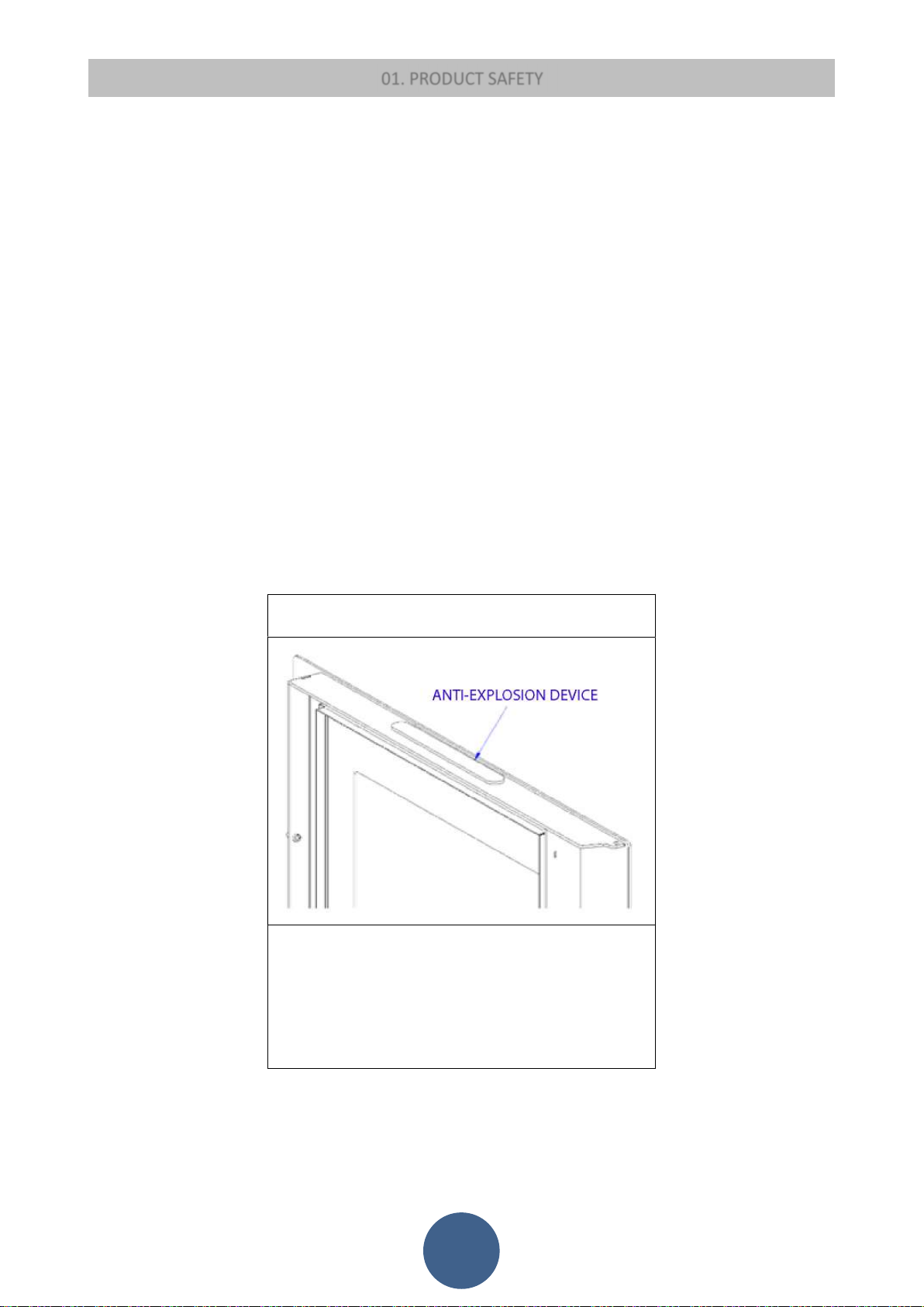
Anti-explosion
Some products are fitted with a safety device to prevent
explosion. Before switching on the product or, in any case, after
any cleaning operation, make sure that the device is correctly
positioned in its seat. The device is located on the firebox door
upper edge.
5
Page 7

01.3 EC CERTIFICATE OF CONFORMITY
01. PRODUCT SAFETY
EVA STAMPAGGI S.r.l.
Via Cal Longa Z.I.
31028 Vazzola (TV) - ITALY
Trademark: EVA CALòR
EN 14785 :2006
Residential space heating appliances fired by wood pellet
Apparecchi per il riscaldamento domestico alimentato a pellet di legno
Type: SPCN9
Model: SILENCE 9
Distance to adjacent combustible materials
Distanza da materiali combustibile
Emission of CO in combustion products
Emissione di CO nei prodotti di combustione
Maximum operating pressure
Massima pressione di esercizio
Flue gas temperature
Temperatura dei fumi
Nominal heat output
Potenza termica nominale
18
5 cm Rear
:
20 cm Sides
- cm Floor
: nominal heat output 0,008 %
reduced heat output 0,030 %
:
-
:
147 °C at nominal heat output
65 °C at reduced heat output
: 8,5 kW
Reduced heat output
Potenza termica ridotta
Efficiency
Rendimento energetico
Fuel type
Tipi di combustibile
Dust emission
Polveri
Electrical power supply
Potenza elettrica assorbita
Rated voltage
Tensione nominale
Rated frequency
Frequenza nominale
: 3,0 kW
: nominal heat output 90,5 %
reduced heat output 96,0 %
: Wood pellet
Pellet di legno
: 18 mg/Nm
11,5 mg/MJ
3
At 13% O
At 0% O2
: 370 W
: 230 V
: 50 Hz
2
6
Page 8
01. PRODUCT SAFETY
3
EVA STAMPAGGI S.r.l.
Via Cal Longa Z.I.
31028 Vazzola (TV) – ITALY
Trademark: EVA CALòR
EN 14785 :2006
Residential space heating appliances fired by wood pellet
Apparecchi per il riscaldamento domestico alimentato a pellet di legno
Type: SPCN11
Model: SILENCE 11
Distance to adjacent combustible materials
Distanza da materiali combustibile
Emission of CO in combustion products
Emissione di CO nei prodotti di combustione
Maximum operating pressure
Massima pressione di esercizio
Flue gas temperature
Temperatura dei fumi
Nominal heat output
Potenza termica nominale
18
5 cm Rear
:
20 cm Sides
- cm Floor
: nominal heat output 0,012 %
reduced heat output 0,024 %
:
-
:
147 °C at nominal heat output
55 °C at reduced heat output
: 10,4 kW
Reduced heat output
Potenza termica ridotta
Efficiency
Rendimento energetico
Fuel type
Tipi di combustibile
Dust emission
Polveri
Electrical power supply
Potenza elettrica assorbita
Rated voltage
Tensione nominale
Rated frequency
Frequenza nominale
: 3,3 kW
: nominal heat output 91,5 %
reduced heat output 97,0 %
: Wood pellet
Pellet di legno
: 18 mg/Nm
11,5 mg/MJ
At 13% O
At 0% O2
: 370 W
: 230 V
: 50 Hz
2
7
Page 9
01. PRODUCT SAFETY
3
EVA STAMPAGGI S.r.l.
Via Cal Longa Z.I.
31028 Vazzola (TV) – ITALY
Trademark: EVA CALòR
EN 14785 :2006
Residential space heating appliances fired by wood pellet
Apparecchi per il riscaldamento domestico alimentato a pellet di legno
Type: SPRV
Model: TRINITY
Distance to adjacent combustible materials
Distanza da materiali combustibile
Emission of CO in combustion products
Emissione di CO nei prodotti di combustione
Maximum operating pressure
Massima pressione di esercizio
Flue gas temperature
Temperatura dei fumi
Nominal heat output
Potenza termica nominale
19
15 cm Rear
:
30 cm Sides
- cm Floor
: nominal heat output 0,008 %
reduced heat output 0,011%
:
-
:
195 °C at nominal heat output
83 °C at reduced heat output
: 9,0 kW
Reduced heat output
Potenza termica ridotta
Efficiency
Rendimento energetico
Fuel type
Tipi di combustibile
Dust emission
Polveri
Electrical power supply
Potenza elettrica assorbita
Rated voltage
Tensione nominale
Rated frequency
Frequenza nominale
: 3,0kW
: nominal heat output 90,0 %
reduced heat output 96,0 %
: Wood pellet
Pellet di legno
: 13,5mg/Nm
9,5 mg/MJ
At 13% O
At 0% O2
: 370 W
: 230 V
: 50 Hz
2
8
Page 10
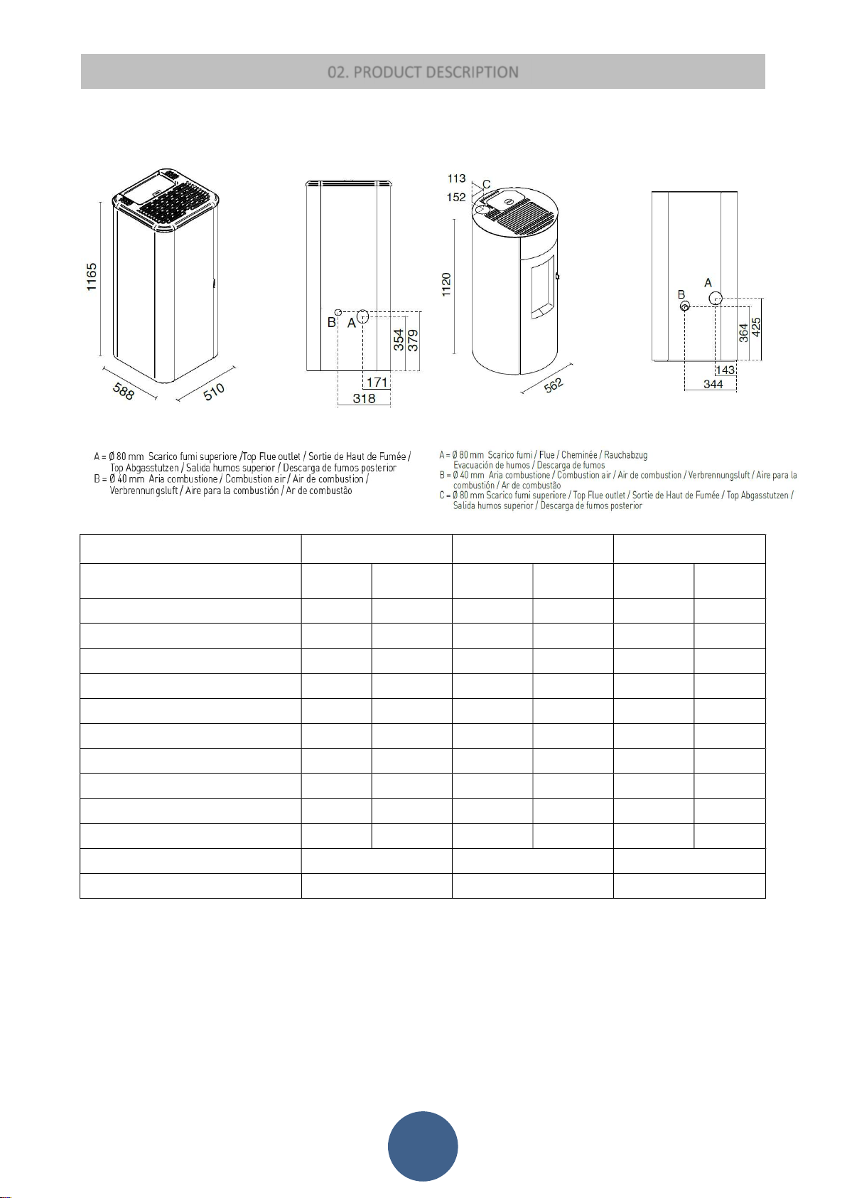
02. PRODUCT DESCRIPTION
Technical data of the appliance:
DISEGNO TECNICO
SILENCE 9 / SILENCE 11 / TRINITY
DATI TECNICI
Dati tecnici dell’apparecchio:
Designation:
Designazione:
Fuel throughput
Consumo orario (kg/h)
Necessary flue draught
Requisiti minimi del tiraggio del camino (Pa)
Flue gas temperature
Temperatura fumi (°C)
Flue gas mass flow
Flusso massico dei fumi (g/s)
Efficiency
Rendimento (%)
Total heating output
Potenza termica (Kw)
CO emission at 13% of O2
Emissioni di CO al 13% di O2 (%)
Electrical power supply
Potenza elettrica assorbita (W)
Rated voltage
Tensione nominale (V)
Rated frequency
Frequenza nominale(Hz)
CLASSE DI EFFICIENZA ENERGETICA
Energy Efficency Class
INDICE DI EFFICIENZA ENERGETICA
Energy Efficency Index
SILENCE 9 electrical consumption:
electrical consumption and nominal power: 37 W
reduced power electrical consumption: 24 W
Stand-By electrical consumption: 3 W
TRINITY electrical consumption:
electrical consumption and nominal power: 94 W
reduced power electrical consumption: 44 W
Stand-By electrical consumption: 3 W
Nominal heat
output
Potenza termica
nominale
1,9 0,7 2,3 0,7 2,3 0,7
147 65 146 55 176 69
5,9 2,7 6,1 2,4 6,4 2,6
90,5 96,0 91,5 97,0 90,0 96,0
8,5 3,3 10,0 3,3 9,0 3,0
0,008 0,030 0,012 0,024 0,008 0,011
370 370 370 370 370 370
230 230 230 230 230 230
SILENCE 9 SILENCE 11 TRINITY
Reduced heat output
Potenza termica
ridotta
Nominal heat output
Potenza termica
nominale
Reduced heat output
Potenza termica
ridotta
Nominal heat output
Potenza termica
nominale
12 10 12 10 10 11
50 50 50 50 50 50
A+ A+ A+
128 129 126
SILENCE 11 electrical consumption:
electrical consumption and nominal power: 50 W
reduced power electrical consumption: 30 W
Stand-By electrical consumption: 3 W
Reduced heat
output
Potenza termica
ridotta
9
Page 11

03. PRODUCT INSTALLATION
03.1 INTRODUCTION
INSTALLATION WITH WALL FUME OUTLET IS PROHIBITED. INSTEAD THE FUME OUTLET MUST BE ROOF-TYPE AS PROVIDED
FOR BY NATIONAL REGULATIONS.
Eva Stampaggi S.r.l. declines any liability for any damage to persons or property arising from the failure to comply with the points
mentioned above and from non-compliant product installation.
Install the stove according to the regulations in force in the country of use.
For example, in Italy this refers to UNI 10683: 2012, which dictates 4 points:
1. preliminary activities - for which the retailer/installer is responsible and liable for at the time of the inspection before definitive installation.
The preliminary activities include:
installation site suitability verification;
fume evacuation system suitability verification;
external air inlet suitability verification.
At this stage it is necessary to check that the product can be safely operated and that it satisfies its technical characteristics.
The safety conditions must be ascertained by means of a prior inspection.
Stoves and fireplaces are heating systems and must be installed safely and comply with the manufacturer's instructions!
2. installation - responsibility of the installer. At this phase the aspects ofinstallation of the product and of the fume evacuation system are
taken into account and the following issues are addressed:
safety distance from combustible materials;
chimney flue construction, smoke ducts, intubated systems and chimney cowls.
3. issuing of additional documents - responsibility of the installer.
Issuing of the technical documentation must include:
manual of use and maintenance of the appliance and of the components of the system (e.g smoke ducts, chimney flue, etc.);
Photocopy or photograph of the chimney flue plate;
system manual: (if applicable);
Declaration of Conformity in relation to Ministerial Decree 37/08.
4. control and maintenance - responsibility of the maintenance technician who must oversee protection and maintenance of the product during
its operation over time. The operator in charge of control and maintenance of the systems for winter and summer climate control performs
these activities to a professional standard, in accordance with the regulations in force. The operator, at the end of these operations, must draw
up and sign a technical inspection report in accordance with the models provided by the provisions of this decree and the implementing rules,
in relation to the type and capacity of the system, to be issued to the person who signs a copy thereby confirming receipt and reading thereof."
THE PRODUCTION OF STOVES WITH HIGHER PERFORMANCE IS INCREASINGLY REQUIRED SO IT IS BECOMES ESSENTIAL TO
ENSURE THAT INSTALLATIONS COMPLY WITH THE LAW. IF THE VENT PIPE PASSES THROUGH NON-HEATED ENVIRONMENTS,
03.2 VENT PIPE
STOVE CHARACTERISTICS FOR SIZING OF THE VENT PIPE
The stove has the following features:
SILENCE 9
Chimney flue draught: 12 Pa
Fume temperature: 147 °C
Mass flow of fumes: 5.9 g/s
TRINITY
Chimney flue draught: 10 Pa
Fume temperature: 195 °C
Mass flow of fumes: 6,4 g/s
SILENCE 11
Chimney flue draught: 12 Pa
Fume temperature: 146 °C
Mass flow of fumes: 6.1 g/s
10
Page 12
03. INSTALLING THE PRODUCT
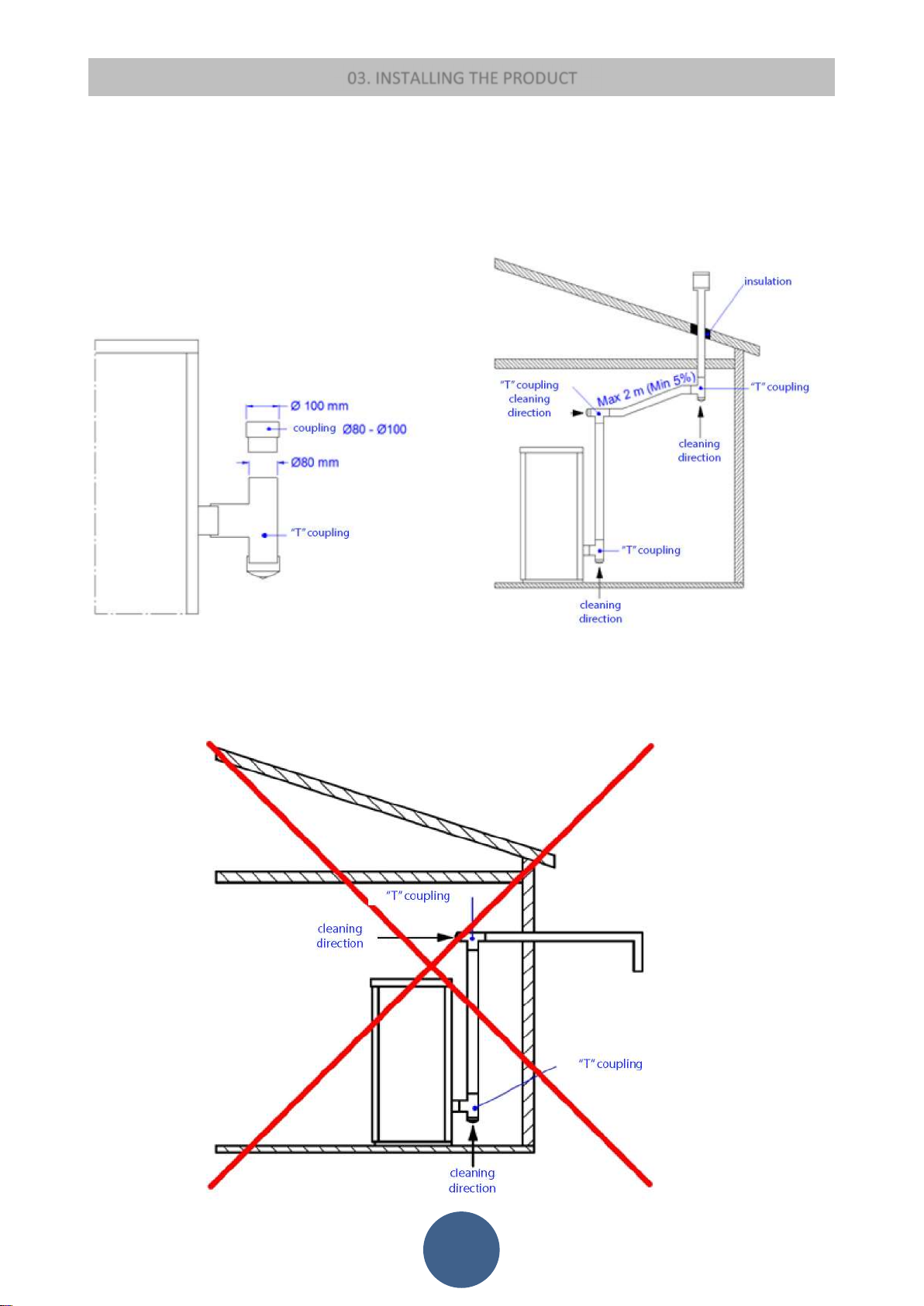
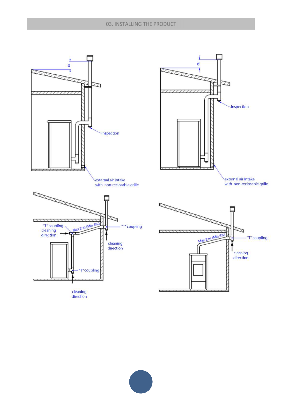
IMPORTANT: THE LENGTH OF THE CHIMNEY MUST HAVE A MAXIMUM OF 6 METERS OF PIPE DIAMETER THAT IS EQUAL
TO OR GREATER THAN THAT SPECIFIED FOR EACH APPLIANCE. EVERY 90° ELBOW OR (T) COUPLING IS THE EQUIVALENT OF
1 METER OF PIPE.
BEFORE CONNECTION TO THE VENT PIPE, IN ORDER TO GUARANTEE CORRECT EFFICIENCY OF THE STOVE, IT IS
NECESSARY TO ENSURE THE FOLLOWING TYPES OF INSTALLATION:
INSTALL THE PRODUCT WITH AT LEAST ONE (T) AND 1.5 METERS OF PIPE CERTIFIED ACCORDING TO EN 1856-2
The vent pipe is one of the key features for guaranteeing the proper functioning of the stove. Thanks to the quality of the materials,
the strength, the durability, the easy cleaning and maintenance, the best vent pipes are made of steel, either stainless steel or
aluminised.
The stove is fitted with a round fume outlet and a joint connection to be connected to the vent pipe.
Use telescopic joint connections to facilitate connection to the steel rigid vent pipe and counterbalance the thermal
expansion of both the firebox and the vent pipe.
Seal the vent pipe joint connection with high temperature silicone sealant (1,000°C). Should the existing flue opening not
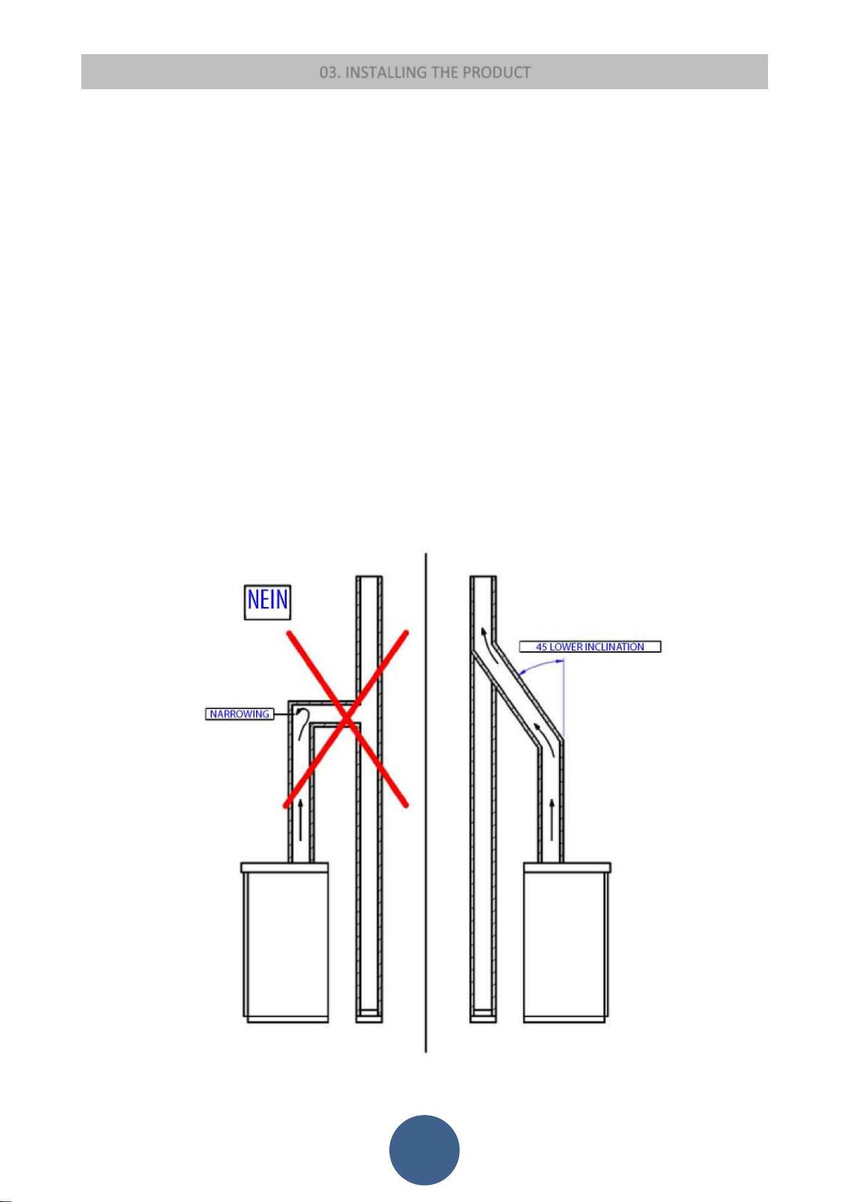
be perfectly perpendicular to the firebox fume outlet, use an elbow to connect them. Inclination must never exceed 45°,
with respect to the vertical axis.
No constrictions. Use 10cm-thick insulating thimbles if pipe vent passes through floors.
The vent pipe must be insulated along its entire length. Thanks to the vent pipe, insulation fume temperature will remain
high optimising draught, preventing condensation and reducing the build-up of non-ignited particles along the vent pipe
walls. Use proper insulating materials (glass wool, ceramic fibre, Class A1 non-combustible materials).
Install a vent pipe with a minimum vertical run of 2 mt to guarantee proper draught.
The vent pipe must be weather-proof and as linear as possible.
Flexible and length-adjustable metal pipes may not be used.
11
Page 13
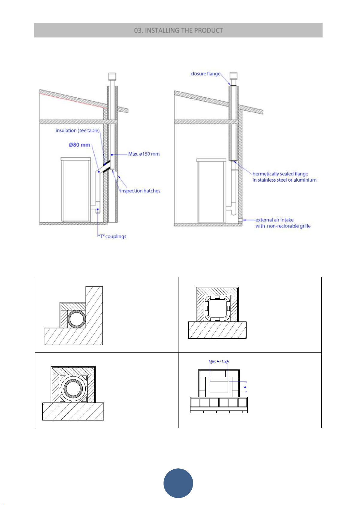
Types of vent pipe
Examples of vent pipe:
03. INSTALLING THE PRODUCT
EXISTING VENT PIPE (TRADITIONAL)
Steel vent pipe with
double chamber
insulated with material
resistant to 400°C.
Optimum efficiency.
Traditional clay vent pipe
with cavities. Optimal
efficiency.
Refractory vent pipe with
insulated double chamber
and external coating in
lightweight concrete.
Optimal efficiency.
Avoid vent pipes with
internal rectangular
section whose ratio
between the larger and
smaller side is greater
than 1.5. Poor efficiency
12
Page 14
03. INSTALLING THE PRODUCT
03.3 CHIMNEY COWL
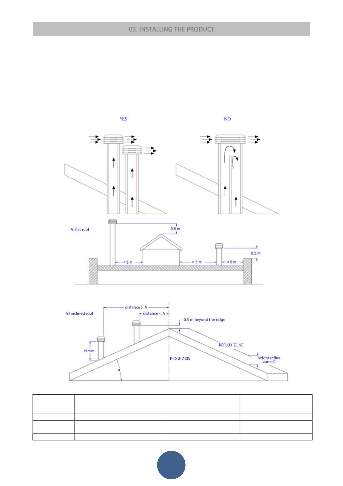
A properly installed chimney cowl ensures optimum stove functioning. The anti-downdraught chimney cowl consists of a number of
components whose outlet section sum always doubles the vent pipe section. Make sure the chimney cowl is at least 150cm above
the roof top so that it is fully exposed to the wind.
The chimney cowls must:
have useful outlet section that is at least twice that of the vent pipe.
be made in such a way as to prevent the penetration of rain or snow.
be constructed in such a way as to ensure, in the event of winds coming from any direction, the evacuation of combustion
products.
be free of mechanical intake auxiliaries.
Roof pitch α [°] Horizontal width of reflux zone
measured from top A axis [m]
15 1,85 1,00 0,50
30 1,50 1,30 0,80
45 1,30 2,00 1,50
60 1,20 2,60 2,10
Minimum height from roof for
discharging exhaust fumes H min
=Z+0.50m
Height of reflux zone Z [m]
13
Page 15
03. INSTALLING THE PRODUCT
03.4 DRAUGHT
Fumes heat up during combustion, increasing their volume. Their density is therefore lower than the one of the surrounding colder
air.
This difference between the inside and outside temperatures of the chimney results in a negative pressure which increases
proportionally to the vent pipe length and the temperature.
The draught must be stronger than the fume circulation resistance so that all exhaust fumes generated during combustion inside the
stove are drawn upwards through the outlet and the vent pipe. Many weather conditions affect the vent pipe functioning, such as
rain, fog, snow, altitude, and wind being the most important as it can create both negative pressure and dynamic loading.
The wind action varies depending on whether it is ascending, descending or horizontal.
Ascending wind always results in an increased negative pressure and draught.
Horizontal wind results in an increased negative pressure as long as the chimney cowl was properly installed.
Descending wind always diminishes the negative pressure, sometimes inverting it.
Excess draught causes an increase in the combustion temperature and consequently a loss in stove efficiency.
Part of the combustion fumes is drawn up through the vent pipe together with small pellet particles before combustion, reducing
stove efficiency, increasing fuel consumption and resulting in the emission of polluting fumes.
At the same time the high fuel temperature, due to an excess amount of oxygen, wears down the combustion chamber sooner than
expected.
On the other hand, poor draught slows down combustion resulting in a decrease in the stove temperature, fume spillage inside the
room, a loss of stove efficiency and dangerous build-up in the vent pipe.
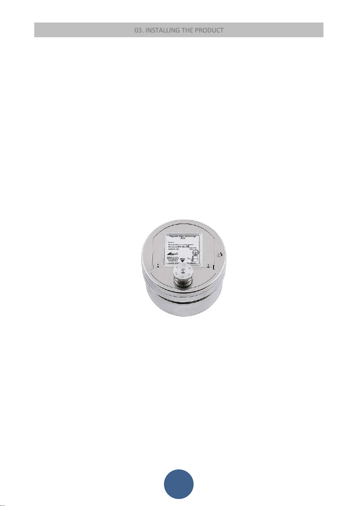
In order to avoid excessive draught it is appropriate to use:
Draught regulator
14
Page 16
03. INSTALLING THE PRODUCT
03.5 STOVE EFFICIENCY
Highly efficient stoves may pose difficulties for fume extraction.
In order for a vent pipe to work properly its internal temperature must increase as a consequence of the fumes generated during
combustion.
Importantly, the efficiency of a heater is determined by its ability to transfer most of the heat produced to the environment to be
heated: consequently, the greater the efficiency of the stove, the "colder" the residual fumes of combustion, and consequently, the
lower the "draft".
A traditional chimney flue, with a rough design and insulation, is more efficient if used with a traditional open fireplace or a poor
quality stove where most of the heat is lost with the fumes.
Therefore, purchasing a quality stove often entails modifying the existing chimney flue to obtain a better insulation, even when it
already works properly with old appliances.
Poor draught results in the stove not operating when hot or in smoke spillage.
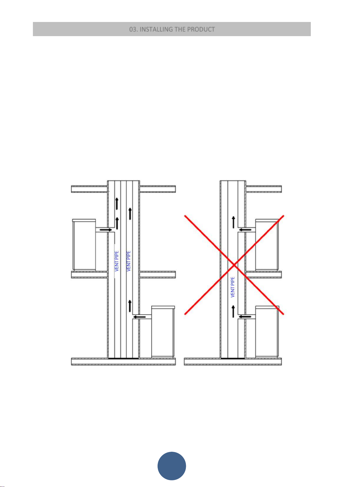
Connecting the stove pipe to an existing chimney flue that has already been used with an old appliance is a common
mistake. In this way two solid-fuel appliances share the same chimney flue, which is wrong and dangerous.
If the two appliances are used simultaneously, the fume load might exceed the existing chimney flue capacity resulting in
downdraught. If only one appliance is used, the fume heat will facilitate draught but the cold air coming from the other
appliance not in use will cool down exhaust fume temperature again blocking the draught.
Besides the problems described so far, if the two appliances are placed on different levels the communicating vessel
principle might be interfered with, causing combustion fumes to be drawn in an irregular and unforeseeable way.
15
Page 17
03. INSTALLING THE PRODUCT
03.6 INSTALLATION
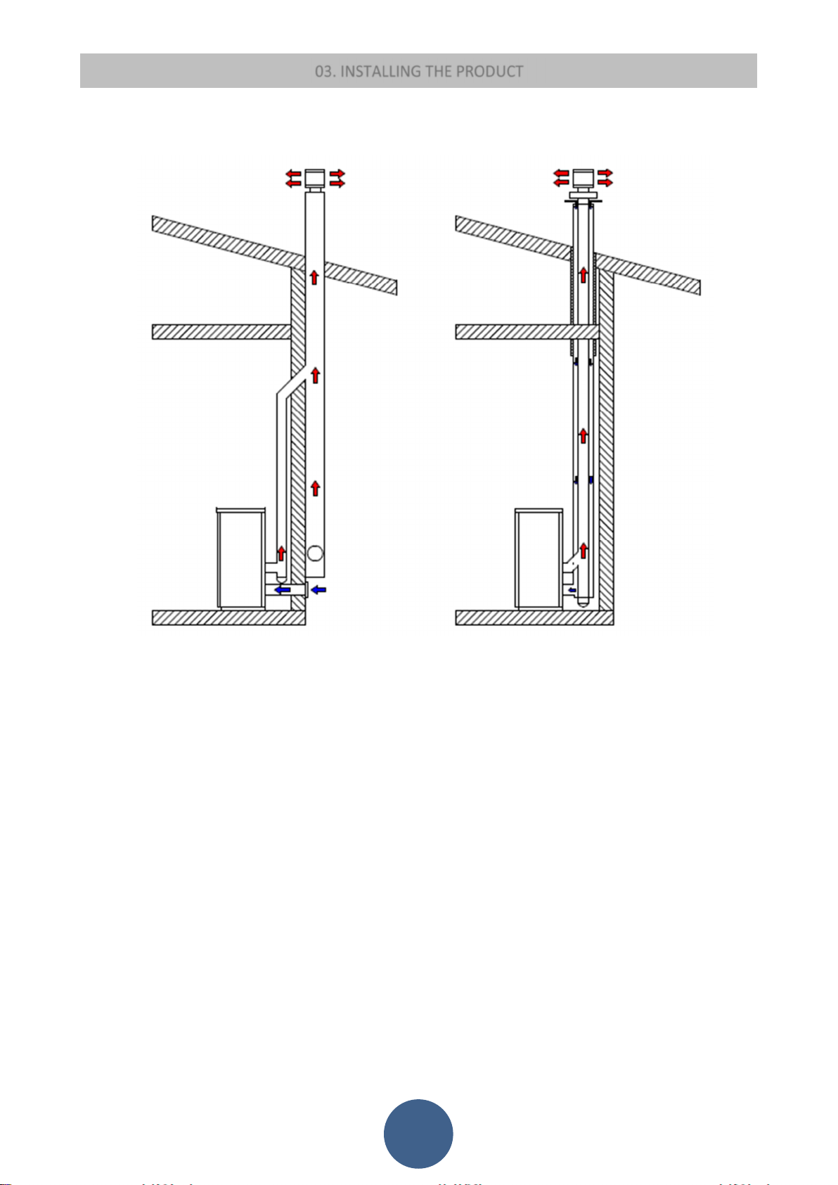
Using coaxial tubes the air will be pre-warmed contributing to improved combustion and lower emissions into the atmosphere
Follow the instructions before installing your stove:
Select the position where the stove is to be installed and:
Arrange the connection to the vent pipe for fume extraction.
Arrange the external air intake (combustion air).
Arrange the connection to the earthed mains.
The electrical system of the room where the stove is to be installed must be earthed, otherwise the control board may not
work properly.
Place the stove on the floor in a convenient position for the connection to the vent pipe and close to the combustion air
intake.
The appliance must be installed on a floor with an adequate loading-bearing capacity.
Should the existing floor not comply with the requirement above, proper measurements must be taken (for instance, the
installation of a load distribution plate).
All the structures which could catch fire if exposed to excessive heat must be protected. Floors made from wood or
inflammable materials must be protected using non-combustible materials (e.g. 4mm-thick sheet metal or ceramic glass).
The appliance installation must ensure easy access for cleaning the stove, exhaust pipes and vent pipe.
This appliance is not suitable to be installed on a shared vent pipe.
During normal operation, the stove draws air from the room where it is installed. Therefore, an external air intake must be
positioned at the same height of the pipe located on the stove back. Exhaust fume pipes must be suitable for pellet stoves
and must therefore be made from coated steel or stainless steel, with a diameter of 8cm and fitted with adequate gaskets.
16
Page 18
03. INSTALLING THE PRODUCT
The combustion air intake must be connected directly to the outside or to adjacent rooms provided they are fitted with
external air supply vents and are not used as bedrooms or bathrooms or, whenever a fire hazard exists, as storage rooms,
garages, combustible material warehouses, etc. The air vents must be placed in such a way that they cannot be clogged
either from the outside or inside and must be protected using a grille, a metal mesh or other suitable means provided they
do not reduce the minimum section.
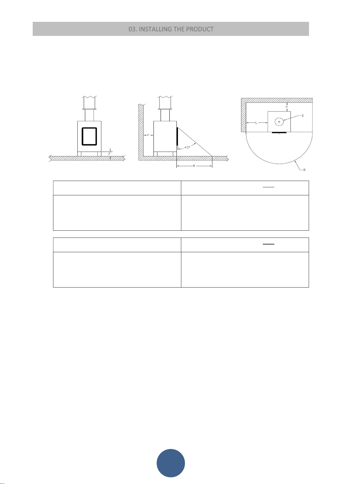
If the stove is to be installed in rooms where it is surrounded by combustible materials (e.g. furniture, wood cladding, etc.),
the following minimum clearances must be complied with:
SILENCE
SAFETY DISTANCE FROM COMBUSTIBLE MATERIALS: SAFETY DISTANCE FROM NON-FLAMMABLE
MATERIALS:
REAR WALL P = 50 mm
SIDE WALL = 200 mm
FLOORING F = 0 mm
FLOOR INSULATION THICKNESS = 0 mm
FRONT R = 1000 mm
TRINITY
SAFETY DISTANCE FROM COMBUSTIBLE MATERIALS: SAFETY DISTANCE FROM NON-FLAMMABLE
REAR WALL P = 150 mm
SIDE WALL = 300 mm
FLOORING F = 0 mm
FLOOR INSULATION THICKNESS = 0 mm
FRONT R = 1000 mm
Besides complying with the minimum clearances set above, we also recommend installing heat-resistant fireproof
insulating panels (rock wool, cellular concrete, etc.)
The following is recommend:
Promasil 1000
Classification temperature: 1000 °C
Density: 245 kg/m3
Shrinkage at reference temperature, 12 h:
1.3/1000°C %
Cold crushing strength: 1.4 MPa
Bending strength: 0.5 MPa
Reversible thermal expansion: 5.4x10
When it is operational, the stove can cause a negative pressure in the room where it is installed. Therefore there should
not be in the same room other naked flame devices, with the exception only of type c stoves (airtight).
Make sure that the stove can draw the necessary quantity of combustion air: this must be from an open space (i.e. a space
without exhaust blowers or providing adequate ventilation) or directly from outside.
Do not install the stove in bedrooms or bathrooms.
Unpack the stove: be careful not to damage the product at the time of unpacking.
Check the stove's legs and adjust them so that the stove is stable.
Place the stove so that the door and any window openings are not against the walls.
After connecting the stove to the combustion air inlet join the coupling device to the vent pipe.
-6
m/mK
REAR WALL P = 50 mm
SIDE WALL = 200 mm
FLOORING F = 0 mm
FLOOR INSULATION THICKNESS = 0 mm
FRONT R = 1000 mm
MATERIALS:
REAR WALL P = 100 mm
PARETE LATERALE L = 200 mm
SIDE WALL = 0 mm
FLOOR INSULATION THICKNESS = 0 mm
FRONT R = 1000 mm
Specific heat capacity: 1.03 Kj/kg K
Thermal conductivity λ:
200 °C 0.07 W/mK
400 °C 0.10 W/mK
600 °C 0.14 W/mK
800 °C 0.17 W/mK
Thickness: 40 mm
17
Page 19
03. INSTALLING THE PRODUCT
HERMETIC APPLIANCES
These stoves draw the combustion air and the air necessary for glass cleaning directly from outside and not from the room where
they are installed, preserving the oxygen in the room. Using coaxial tubes the air will be pre-warmed contributing to improved
combustion and lower emissions into the atmosphere. Ideal for passive houses, they offer best comfort at the lowest cost. The
stove works even if not connected to the external air intake.
INSTALLATION EXAMPLE:
:
ESEMPIO DI INSTALLAZIONE ERRATA:
I tubi di espulsione dei fumi non devono mai essere installati in modo che i gas di evacuazione siano con uscita diretta orizzontale o
orientati verso il basso.
EXAMPLE OF INCORRECT INSTALLATION:
Exhaust pipes must never be fitted pointing downwards or horizontally so that fumes are discharged directly through the external
wall.
18
Page 20
EXAMPLE OF INCORRECT INSTALLATION:
03. INSTALLING THE PRODUCT
19
Page 21
03. INSTALLING THE PRODUCT
HANDLING AND UNPACKING
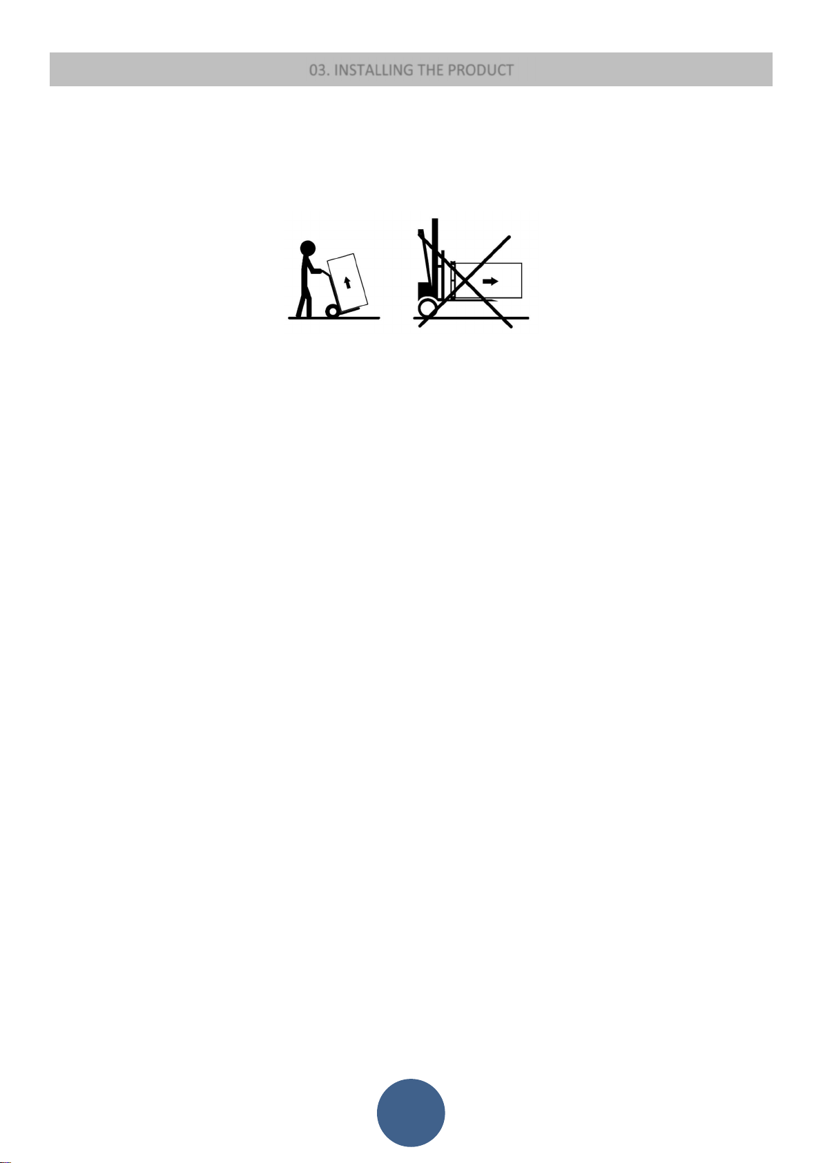
At the time of transportation do not position the product horizontally. Unloading of the product must be performed using lifting means that are
suitable and that have characteristics that are consistent with the weight of the stove. The operator must make sure that during offloading and
lifting of the stove there are no persons or objects nearby. At the time of unpacking avoid damaging the product with cutters or blunt tools. Keep
the packaging out of the reach of children. Unscrew from under the pallet the screws that secure it to the latter and position the stove at the
dedicated point paying attention to any impediments that could prevent installation or damage the product.
STOVE INSTALLATION
In compliance with the current regulations for installation, the stove must be installed in a ventilated place with air that is sufficient to ensure
correct combustion and therefore good operation. The room must have a volumetry of no less than 20 m3 and to ensure good combustion (40
m3/h of air), there must be a "combustion air intake" that must reach a wall that connects to the outside or to adjacent rooms provided they
are fitted with external air supply vents (Ø80mm) and are not used as bedrooms or bathrooms or, whenever a fire hazard exists, as storage
rooms, garages, combustible material warehouses, etc. These air vents must be placed in such a way that they cannot be clogged either from
the outside or inside and must be protected using a grille, a metal mesh or other suitable means provided they do not reduce the minimum
section.
The stove must not be positioned close to curtains, armchairs, furniture or to other flammable materials.
The stove must not be installed in explosive or potentially explosive environments which may become explosive due to the presence of
machinery, materials or dust that can cause greenhouse gas emissions or which can easily ignite with sparks. Before attempting to install the
pellet stove, bear in mind that all fixtures or any beams made of combustible material must be placed at a safe distance and outside the radiation
area of the stove itself.
The fume outlet can be located on the upper side or on the rear side of the stove. You can decide between the rear and the top fume outlet
based on the location of the vent pipe.
THE STOVE DOES NOT WORK IF THE LID OF THE PELLET HOPPER IS OPEN.
ELECTRICAL CONNECTION
The electrical connection must be performed by qualified personnel who install circuit breakers upstream of the appliance.
Special attention should be paid when the operation is a supplementary action and all equipment must operate as planned.
Avoid installations with electric cables that run close to fume pipes or hot components that are suitably insulated.
The voltage is 230 V while the frequency is 50 Hz.
The electrical system where it is connected must be fitted with a conductor as required by the Regulations 73/23 EEC and 93/98 EEC.
EXTERNAL THERMOSTAT
In this product it is possible to install an external thermostat. This operation may only be performed by authorised personnel. Use a 2-pole cable
with everyday double insulation. Connect the two poles to the connector of the CN7 pin 7-8 electronic board. Enable the external thermostat,
changing the room temperature with the P2 key until obtaining of the word T-E. On the home screen the room temperature will disappear and
T-ON will be displayed when the thermostat requests and T-OF when the thermostat is compliant. If the thermostat is closed, the appliance
works at the set heat output. If the thermostat opens, the appliance will work in the MODULATE state until switching off if STAND-BY is activated.
POWER ON
First connect the stove plug to the mains and load the pellet hopper.
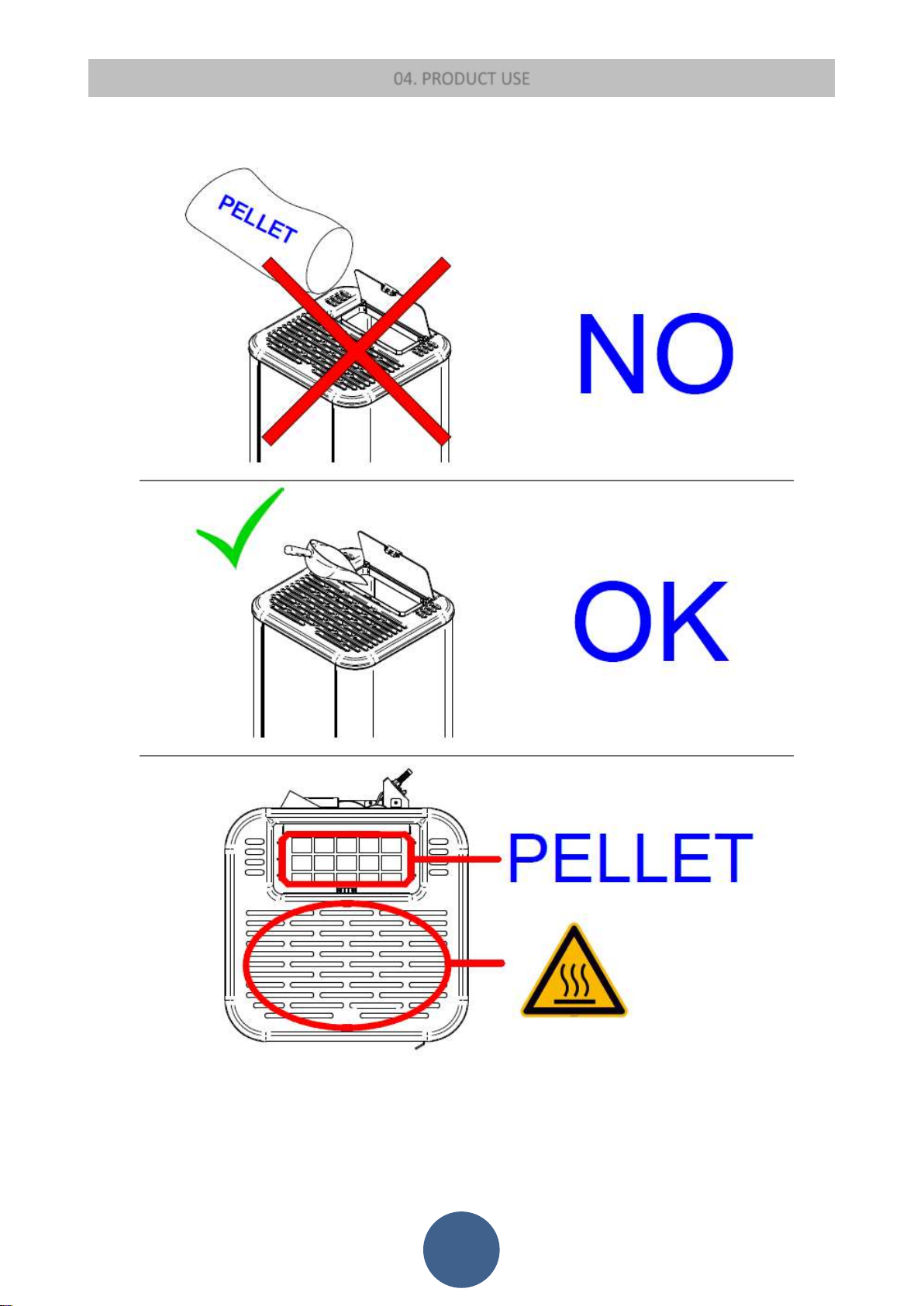
For this operation it is very important not to empty the entire bag in one go but to perform the operation slowly to avoid pouring the powder
of the pellets present in the bag into the hopper. If applicable, be careful not to damage the gasket in the door of the pellet hopper and keep
the support surface of the latter clean.
The pellets must not be of a cheap quality. The characteristics are listed in the PRODUCT SAFETY chapter. The use of substandard pellets can
prevent the stove from reaching maximum yield due to poor combustion and degradation of the stove itself. Check that the door of the pellet
hopper is fully and correctly closed otherwise the stove will not work properly.
The ash collection drawer must be closed. There is an end of stroke contact in the door that in case it is not closed correctly removes the power
supply to the auger tube and would send the stove into alarm.
Load the pellets then from the main menu perform the INITIAL LOAD, and then turn on the stove.
The burn pot cleaning mechanism is present in the stove. Before loading the pellets, the stove activates this cleaning device so that the burn
pot is always clean to obtain the highest yield possible. This cleaning phase lasts on average 4 minutes. After cleaning, if all the mechanisms
have successfully concluded their cycle then PELLET LOADING will take place otherwise there will be an alarm that will interrupt the ignition
phase.
20
Page 22
04. PRODUCT USE
21
Page 23
04. PRODUCT USE
04.1 RADIO CONTROL
Proper functioning and control adjustment devices
Console
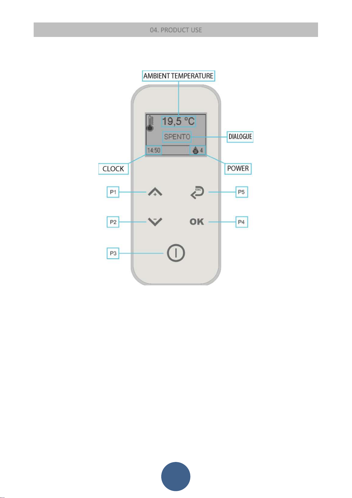
The radio control shows the information concerning the stove operating status. Several types of data can be displayed and the
settings available according to the access level can be modified by entering the menu. Depending on the selected mode and on
their position on the display, the data visualised may acquire different meanings.
Description of Panel
BUTTON 1 - Increase:
When in programming mode, use this button to modify/increase the selected menu value. When in working/switched off mode,
instead use this button to increase the room thermostat temperature value or stove heat output.
BUTTON 2 - Decrease:
The button in programming mode modifies/decreases the selected menu value, in work/off mode it decreases the temperature
value of the room thermostat or stove heat output.
BUTTON 3 - ON/OFF release:
Hold this button down for two seconds to manually switch the stove on or off respectively depending on its initial status (switched
on or off).
By simply pressing, the radio control display comes on. Should have any alarm blocked the stove, press this button to unlock it and
subsequently switch it off.
BUTTON 4 – Confirm
BUTTON 5 – Back
22
Page 24
Emergency console
04. PRODUCT USE
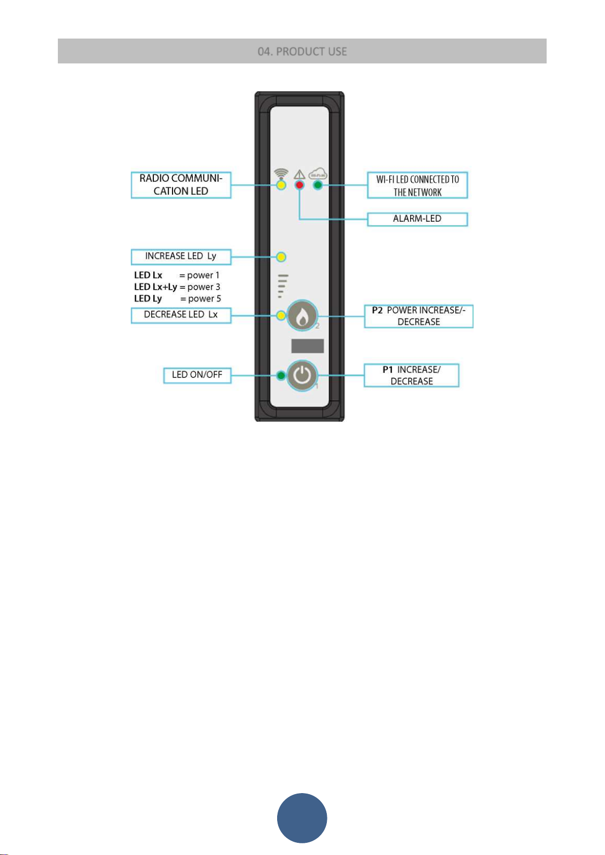
The emergency console is used when the radio control does not work or in case of loss of the latter.
BUTTON P1: On / Off
Keeping this button pressed, the stove will switch on or off according to the last settings recorded by the radio control.
P2 BUTTON: to increase/decrease the heat output
With this button it is possible to select the stove heat output manually.
REMOTE CONTROL CONNECTION
First ignition and association of the radio remote control to the stove: it is necessary to interface the radio remote control to the
emergency display. There are 2 possibilities:
1) with the board off, press the two radio control keys (ok+on-off) until the radio id menu appears. At this point press the - key and
the word "NEW" appears. Press the "OK" key and select the desired channel number (+ and - keys). Turn on the board and press the
"OK" key on the radio control to confirm.
2) with the board on press the two keys of the radio control (ok+on-off) until the radio id menu appears. At this point press the - key
and the word "NEW" appears. Press the "OK" key and select the desired channel number (+ and - keys). Press the two buttons on the
emergency console until all the LEDs flash. At this point press the "OK" key on the radio control to confirm.
23
Page 25

04. PRODUCT USE
The menu
Press the P4 button to access the menu.
It includes several items and levels to access settings and control board programming.
USER MENU
The table below briefly describes the menu structure, focusing in particular on the functions available to users.
STAND-BY
In this menu it is possible to activate or deactivate the automatic stand-by of the stove. When selected, if the room temperature
exceeds the set temperature by 2°C, the stove will automatically switch off and then switch on again when the room temperature
drops below 2°C with respect to the set temperature.
DATE AND TIME
Use this function to set current time and date. The control board is equipped with a lithium battery guaranteeing the time clock 3/5
year-long autonomy. Set the current date by pressing OK and the respective arrows to increase or decrease the selected values.
CHRONO
Chrono Enable Submenu
The menu shown on the "Enable Chrono" display allows overall enabling and disabling of all the chronothermostat functions. To
enable, press the P1 button. Press P3 button to confirm.
Day Chrono Submenu
Once the "Day Chrono" menu has been selected, the daily chrono is enabled using the P1 and P2 buttons. With the P4 button, the
possible items can be scrolled through, including: switch-on time, switch-off time, set stove heat output, room temperature. It is
possible to set two operating ranges. The OFF setting tells the clock to ignore the command. To change use the keys P1 and P2 while
to confirm press P3.
Weekly Chrono Submenu
The "Weekly Chrono" menu allows enabling/disabling and setting of the weekly chronothermostat functions. The weekly
programming function features 4 independent programmes. Moreover, if the time is set to OFF, the time clock ignores the
corresponding control. To change use the keys P1 and P2 while to confirm press P3.
In each program you will find: Switch-on time, Switch-off time, Set stove heat output, room temperature, days of the week in which
the program is to be active. Monday is 1 and Sunday is 7.
Week End Chrono Submenu
It is used to enable/disable and to set the chronothermostat functions on weekends (days 6 and 7, i.e. Saturday and Sunday). To
enable, press the P1 and P2 buttons. Setting the times Start 1 and Stop 1 sets the operating period for Saturday, while Start 2 and
Stop 2 are used to set the stove operation for Sunday.
LANGUAGE
Use this function to select one of the languages available. To move to the next language press P1 (increase) to go back, press P2
(decrease) and to confirm press P4.
SETTINGS
In this menu you will find:
BOARD BEEP: this is the buzzer in the board. With this submenu it is possible to activate or deactivate
BACKLIGHT ON: duration of the radio control lighting
POWER ON: duration of the display on
BRIGHTNESS: on or off
CONTRAST: to adjust the display contrast
KEYS TONE: to deactivate or activate the radio control keys beep
INITIAL LOAD
This function is only available when the stove is OFF and allows the auger tube to be loaded the first time the stove is started, when
the pellet hopper is empty. After selecting the menu, press P1. The exhaust blower switches on at the maximum speed and the auger
tube (auger tube LED on) starts working. They will switch off once the period of time indicated on the display has elapsed or after
pressing the P3 button
24
Page 26

04. PRODUCT USE
STOVE STATUS
Enter the STOVE STATUS menu, after pressing the P4 button, the display scrolls the status of a number of variables during operation
of the stove at work.
WI FI STATUS
Enter the WI FI STATUS menu, after pressing the P4 button, the status of a number of variables of the Wi-Fi status scrolls on the
display. The options can be reset within this menu.
USER SETTINGS
In this menu it is possible to increase or decrease by a pre-set percentage the falling of pellets due to the change of the pellet itself.
TECHNICAL MENU
This menu item is reserved to the stove installer.
BLOWER MODE
In this menu it is possible to activate or deactivate the ambient ventilation. It is possible to do this in any power.
User functions
Standard functioning of a control board properly installed on an air stove is described below with reference to the functions available
to users.
Stove ignition
Hold P3 button down for a few seconds to switch on the stove. Ignition is signalled in the display with the word "Check up".
In these conditions the stove is in the pre-heating state, the burn pot is cleaned, the glow plug (visible with the glow plug LED) and
the fume extraction fan come on.
Any problem detected during the switching-on phase is indicated on the display and the stove goes into the alarm status.
Pellet feeding
After approximately 1 minute the pellet loading phase begins and the message "Load Pellets" appears on the display. During the
initial phase, the auger tube loads the pellets into the burn pot for a fixed time. In the second phase the auger tube turns off, while
the speed of the fumes and the glow plug remain in the previous state. If ignition does not occur after this phase, the auger tube is
switched on again and the glow plug remains on.
Fire present
Once fume temperature has reached and exceeded a pre-set threshold, the stove goes into the ignition mode and the message “Fire
Present” appears on the display.
The speed of the fumes is fixed, the auger tube turns on for a fixed time and the glow plug is turned off. Any problem during this
phase will cause the control board to stop and the stove to go into error state.
Stove operational
After the temperature of the fumes has reached and exceeded a given value and has maintained it for at least a predetermined time,
the stove goes into work mode which is the normal operating mode. The upper display shows the time and the room temperature
and the lower one the set power and the power in which the stove is found. The heat output can be set by pressing the P2 key and
the room temperature can be set by pressing the P1 button. If the fume temperature reaches a certain set threshold, the air
exchanger fan turns on. Room ventilation can be excluded from the BLOWER MODE menu.
During this phase, the stove cleans the burn pot. The message "Cl-burn pot”" appears on the display, the auger tube turns on (auger
tube LED on), the exhaust blower is on. Once the set period of time has elapsed, the stove goes back to the working mode.
Changing set heat output
During stove normal operation (Work), the heat output can be changed by using the P2 button. Press the P2 button again to increase
the heat output and the P1 button to decrease it. The display will show the set heat output. To exit the set, wait 5 seconds without
performing keyboard operations, or press P3 or P4.
Changing set room temperature
Press P1 button to change the set room temperature. The display shows the set room temperature (SET temperature value). Press
P1 and P2 buttons to increase or decrease, respectively, the temperature value. The value is saved after approx. 5 seconds and the
display goes back to normal. Otherwise, press P3 or P4 to exit.
25
Page 27

04. PRODUCT USE
Room temperature reaches the set value (SET temperature)
When the set room temperature value is reached, the stove heat output is automatically set to the minimum value. During this phase
the display shows the message "Modula". If room temperature falls below the set value (Set temperature value), the stove will go
back to the "Work" mode and to the previously set heat output (Set heat output). If there is an external thermostat and the room
temperature has been set to t-e, if the thermostat is open it will begin modulation and if closed, it will return to the heat output set.
Stand-by
When enabled in the menu, the Stand-by function allows the stove to be switched off after complying with the following conditions.
It is enabled if, for a certain time, the ambient temperature is higher than the set temperature (Ambient set) plus a pre-set
temperature delta. The display shows "Standby" and then the remaining minutes. At the end of the given time, the message "Wait
for cooling" appears on the display. In this state, the stove has an auger tube closed (auger tube off) and the heat exchanger switches
off. When the fume temperature reaches a given threshold, the stove enters the stand-by mode and scrolls the wording "Stop eco
temp". The auger tube is switched off (auger tube LED off), the heat exchanger is switched off, as is the exhaust blower .
If the room temperature falls below the set temperature (Ambient set) minus the threshold given by the temperature delta, the stove
switches on again.
Stove switch off
Hold P3 button down to switch off the stove. The message "SWITCH OFF" appears on the display. The auger tube motor stops (the
auger tube LED is off) and the exhaust blower speed is pre-set. The fan of the exchanger (exchanger LED on) remains active until the
fume temperature falls below a pre-set value. After a certain time, if the temperature of the fumes is below a given threshold, the
stove switches off, displaying the message "Off".
Wi-Fi
The configuration procedure is as follows:
1. From a device with a Wi-Fi device (computer/tablet/smartphone), it is necessary to connect to the Wi-Fi network
created by the Wi-Fi module. The name of the network to be searched for (SSID) will be similar to “Evastampaggi-
Wifi_000780FFFFFF”. 2. Verify that the Wi-Fi device (computer/tablet/smartphone) has established the actual
connection to the network created by the Wi-Fi module.
3. Open the browser of the device in use (Internet Explorer, Firefox, etc.) and in the address bar
type in the following address: http://192.168.1.1.
4. The main page of the Wi-Fi module will open, showing certain information about its operation.
8. choose the desired language and continue.
9. Select the network to be used from the list to connect the device to the Internet and enter the password of the
selected network.
10. Click the 'Connect' button to connect the module to the Internet.
11. you will see the message: the device is connecting, wait 30 seconds. The green LED of the wi fi connection is flashing.
12. After a few seconds from the Internet connection, the green LED will light up to indicate that the module has
completed the configuration procedure correctly.
13. At this point the product you have purchased is permanently connected to the Internet.
Now open the browser of the device in use and in the address bar type the following address:
http://evastampaggi.efesto.web2app.it/.
The page of the EFESTO Web App will open, click in the "Register" section of the main menu. Once registered, you will
receive a confirmation e-mail in your mailbox.
14. Return to the main page of the EFESTO Web App and access your account by entering the data (e-mail address and
password) previously used during registration. It is now possible to insert a new device by clicking on the "Add stove"
section of the main menu.
During this procedure you will be prompted for:
- ITEM NUMBER and SERIAL NUMBER that you can find on the back of your electronic device (pellet stove, boiler, etc.),
(the ITEM NUMBER corresponds to the MODEL and the SERIAL NUMBER corresponds to the SERIAL on the label on the
back of the device)
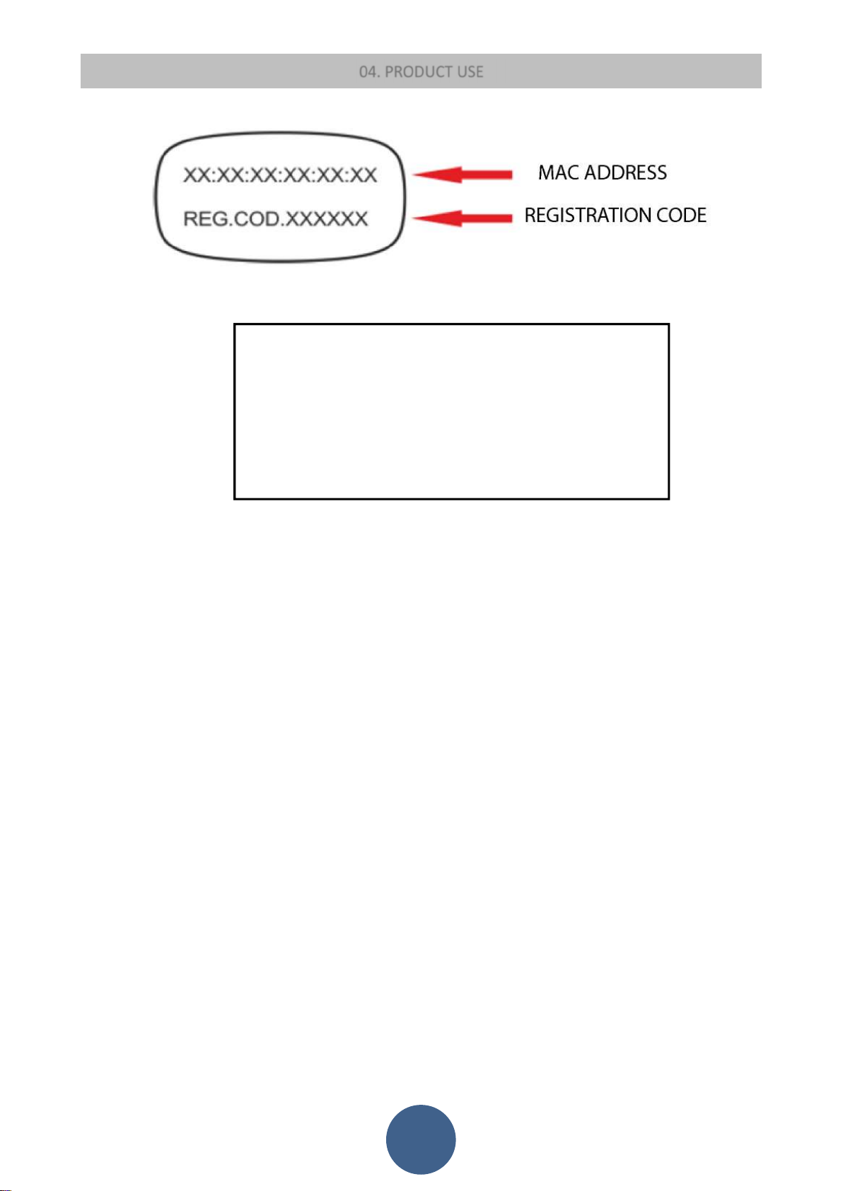
- MAC ADDRESS and REGISTRATION CODE that you will find on the back of your Wi-Fi module (see figure below)
26
Page 28
04. PRODUCT USE
TEST PASSED
MODEL: =CODICE ARTICOLO / ITEM NUMBER
At this point your electronic device (pellet stove, boiler, etc.) has been added and can now be managed via the Web
App from your device (computer/tablet/smartphone).
You are now able to autonomously manage all the available functions of the product you have purchased from your
device.
SERIAL: =SERIAL NUMBER
FIRMWARE:
27
Page 29
04. PRODUCT USE
Alarms
In the event that an operating anomaly occurs, the board intervenes and signals the occurrence of an irregularity, turning on the alarm LED
(alarm LED on) and emitting acoustic signals.
The possible alarm messages are listed below:
Display shows
ALARM BLACK-OUT
ALARM FUME TEMP.
ALARM REG. ENCODER
ALARM NO ENCODER
ALARM IGNITION UNSUCCESSFUL
ALARM CHECK PELLETS
ALARM THERMAL SAFETY
ALARM NO DEPRESSION
ALARM AUGER TUBE SAFETY
ALARM INSUFFICIENT DRAUGHT
ALARM CLEANER FAULT
ALARM AUGER TUBE ENCODER
ALARM AUGER TUBE TRIAC
In case of alarm, the stove is always immediately switched off
EXCEPT FOR THE POWER OUTAGE ALARM, the alarm status is reached at the end of the period of a time set by and can be cleared by holding
P3 button down. Whenever an alarm is cleared, the stove starts a switching-off phase for safety reasons. The alarm LED (alarm LED on) will
remain on and the buzzer, if enabled, will sound intermittently during the entire alarm phase. Should the alarm not be cleared, the stove will in
any case be switched off and the alarm message will remain on the display.
No.
(1)
(2)
(3)
(4)
(5)
(6)
(7)
(8)
(10)
(11)
(12)
(13)
(14)
Cause
Absence of mains voltage
Fume overheating
Check encoder
Fume fan fault, not working
Stove does not ignite
Shutting down due to insufficient pellets
Safety thermostat activated
Depressor activated
The auger tube turns continuously
Burn pot or air extraction pipe obstructed
The burn pot cleaner is blocked
The board does not read the auger tube encoder. No connection
The auger tube turns continuously
Safety thermostat
If the general safety thermostat detects a water value exceeding the trigger threshold, it
immediately switches off the auger tube (to which it is connected in series), while acquiring this
change in status. The message THERMAL SAFETY ALARM appears on the display and the system is
switched off. Unscrew the black cap on the back of the stove and press the button to reset the
contact.
Negative Pressure Alarm
This alarm occurs if:
The vent pipe is non-compliant: the pipe must minimise the Pascals required by the manufacturer (see TECHNICAL DATA) at both low
and maximum power.
Vent pipe or combustion air outlet obstructed.
Combustion chamber door and/or pellet hopper door open.
Excessive dirt inside the fume fan: it is necessary to empty the ash that settles in the area adjacent to the ash drawer compartment.
Black-out Alarm
In the event that there is an electrical power failure for a given time, the stove, with restoring of the electricity, will change to BLACK-OUTalarm.
It is necessary to wait for the stove to cool down and then turn it back on.
28
Page 30
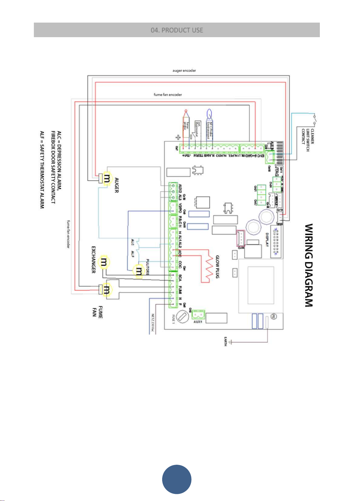
Connections
04. PRODUCT USE
29
Page 31
05. CLEANING AND MAINTENANCE
05.1 INTRODUCTION
The stove requires a simple yet constant cleaning to guarantee top efficiency and proper functioning.
Constant maintenance by a qualified technician is recommended.
The stove should be cleaned before the cold season because it can sometimes get clogged during the summer (by nests for example)
preventing exhaust fumes to flow regularly.
At the beginning of the season and in case of wind, a build-up of residue in the pipe may lead to fires. Should this happen, find below
a few pieces of advice to follow:
Block air supply to the pipe immediately;
Throw sand or kitchen salt, and not water, to extinguish fire and coals;
Keep objects and furniture away from the burning pipe.
ALSO TO PREVENT THIS TYPE OF FAULT YEARLY CLEANING OF THE VENT PIPE IS ESSENTIAL, REMOVING DEPOSITS OR ANY POCKETS
OR OBSTRUCTIONS.
ATTENTION:
USE A DRY CLOTH TO CLEAN THE STOVE EXTERNALLY.
THE AUGER TUBE MUST BE COMPLETELY EMPTIED FROM PELLETS WHEN USING THE STOVE FOR THE LAST TIME AT THE
END OF THE SEASON. THE AUGER TUBE MUST REMAIN EMPTY TO PREVENT IT FROM BECOMING CLOGGED BY SAWDUST
RESIDUES THAT HAVE SOLIDIFIED DUE TO MOISTURE.
05.2 ORDINARY CLEANING
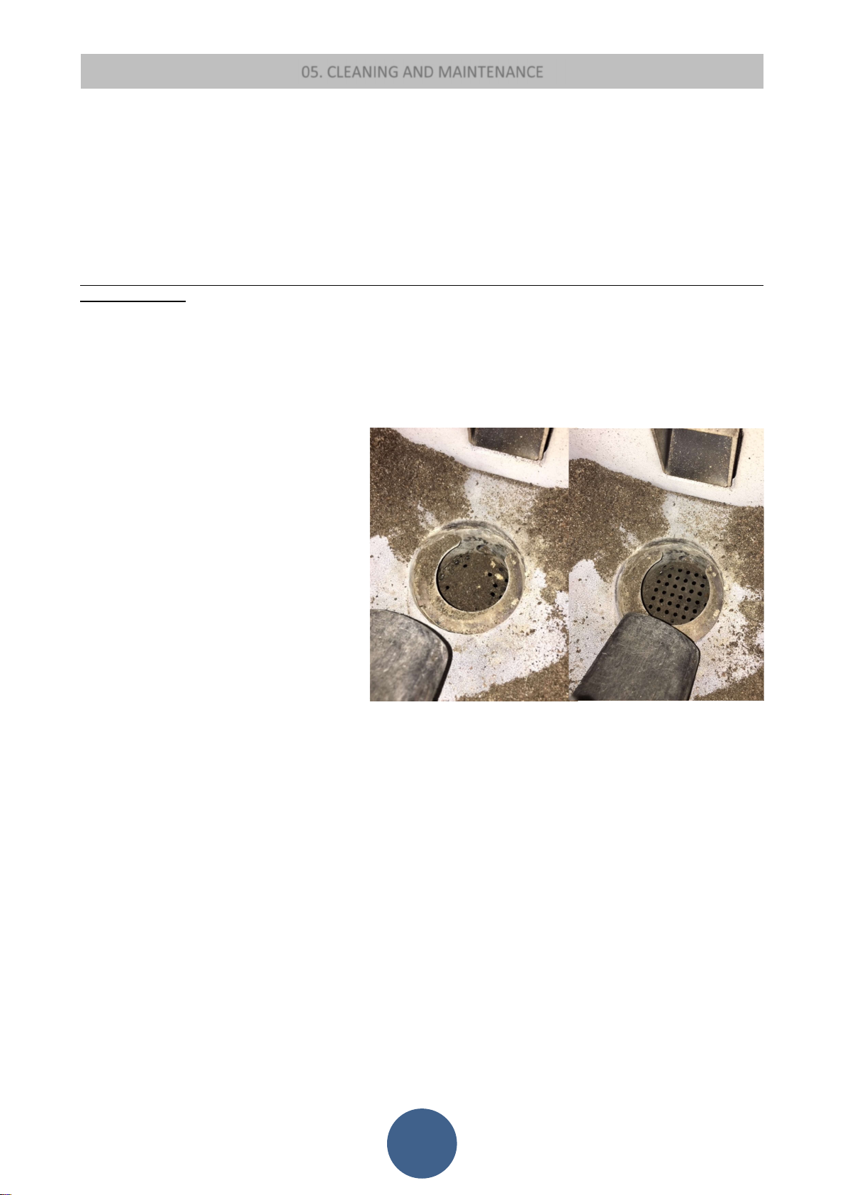
Each time the stove is turned on, it performs a burn
pot cleaning cycle automatically.
If the automatic cleaning has not cleared the holes in
the burn pot, it is necessary to do this using an ash
vacuum.
Any cleaning operation must be performed when the
stove is completely cold:
Check every day that there are no residues
in the combustion chamber and the level
of the ash drawer.
The ash drawer must be emptied according
to use and type of pellets approx. every 5
days.
Vacuum the combustion chamber: check
that there are no embers that may still be
lit. In this case your dust vacuum cleaner
will catch fire.
Remove the ash inside firebox and on door.
Wipe the glass with a damp cloth or a damp ball of newspaper dipped into the ash. If the operation is performed with the
stove hot there is a risk of the glass exploding.
ATTENTION: USE A DRY CLOTH TO CLEAN THE STOVE EXTERNALLY. DO NOT USE ABRASIVE MATERIALS OR PRODUCTS THAT MAY
CORRODE OR LIGHTEN THE SURFACES.
05.3 MANUFACTURER LIABILITY
The manufacturer shall not be held liable against any direct and/or indirect, criminal and/or third party liability arising from:
failure to abide by the instructions contained herein.
non authorised repair operations or changes.
use not compliant with safety rules.
installation not compliant with national current regulations and safety rules.
insufficient maintenance.
the use of spare parts that are not original or which are not specific to the stove model.
Period of inactivity
During the periods of inactivity we recommend that you remove any remaining pellet from the hopper and disconnect the stove from
power supply by pulling out the power cord or by using the relevant ON/OFF switch.
30
Page 32
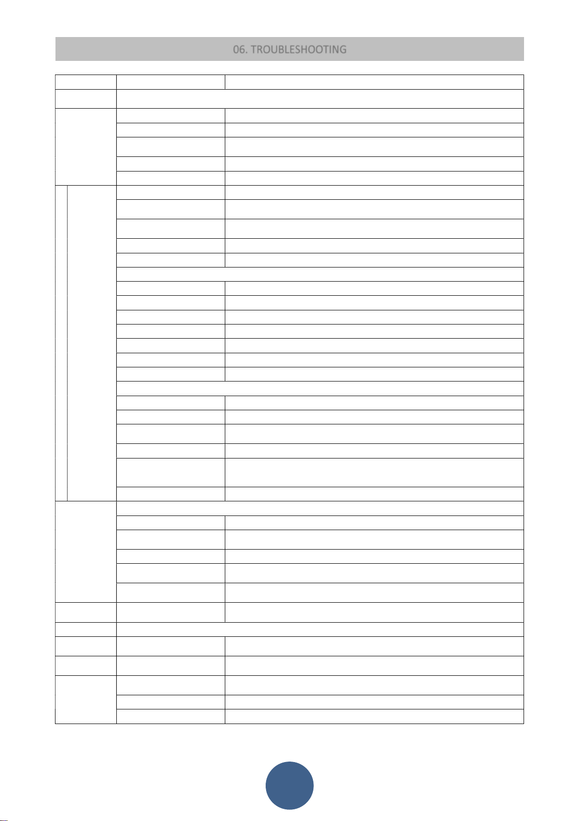
06. TROUBLESHOOTING
IT MAY BE NECESSARY TO REPEAT THE FIRST LOAD PHASE A FEW TIMES TO FACILITATE THE APPLIANCE INITIAL
START
-
UP
INTERRUPTED FUSE IN
ALARM
NO FIRE
SAFETY THERMOSTAT
AUGER TUBE BLOCKED BY
AUGER TUBE BLOCKED BY
INSUFFICIENT PELLET SET
COMBUSTION AIR NOT
FAULTY / DIRTY
EXHAUST
INADEQUATE COMBUSTION AIR
ALARM NO
DISPLAY DOES
SET ROOM TEMPERATURE
INCREASE SET ROOM TEMPERATURE SO THAT APPLIANCE GOES BACK TO "WORKING"
PERIODIC CYCLE OF BURN POT
EXCESSIVE OR INADEQUATE
PROBLEM CAUSE SOLUTION
FIRST START-UP
DISPLAY
SWITCHED OFF
PELLETS NOT
FED TO
BURN POT
PELLETS
FALL BUT
NOT LIT
STOVE
SWITCHES
OFF DURING
NORMAL
FUNCTIONIN
G
AS THE AUGER TUBE IS COMPLETELY EMPTY AND IT MAY TAKE A SPECIFIC PERIOD OF TIME TO FILL.
POWER OUTAGE CHECK PLUG AND POWER SUPPLY.
FAULTY ELECTRICAL CABLE CALL TECHNICAL ASSISTANCE.
CONTROL BOARD
FAULTY CONTROL BOARD CALL TECHNICAL ASSISTANCE.
FAULTY DISPLAY CALL TECHNICAL ASSISTANCE.
NO PELLETS
TRIGGERED
FOREIGN BODY
FAULTY AUGER TUBE MOTOR
ACTIVE ALARM
DIRTY BURN POT
TEMPERATURE TOO COLD
DAMP PELLETS
FAULTY IGNITION PLUG
FAULTY FUME SENSOR
FAULTY EXHAUST BLOWER
FAULTY CONTROL BOARD
POWER OUTAGE
NO PELLETS
FOREIGN BODY
POOR QUALITY PELLETS
VALUE AT MINIMUM HEAT
OUTPUT
ACTIVE ALARM
ANTI-EXPLOSION DEVICE PLUG MISSING OR NOT CORRECTLY POSITIONED.
PARTIALLY CLOGGED VENT PIPE CLEAN VENT PIPE IMMEDIATELY.
CALL TECHNICAL ASSISTANCE.
ALA
RM NO FIR
E
POOR FLAME
NETWORK
RiS / ECO SET ROOM TEMPERATURE REACHED / STOVE WORKS PROPERLY.
NOT WORK
STOP FIRE
ALARM DEP
SUFFICIENT
CLOGGED STOVE CLEAN BURN POT AND ASH DRAWER.
BLOWER
SET VALUE
POWER OUTAGE SWITCH STOVE ON AND OFF, CHECK PLUG.
REACHED
CLEANING
VENT PIPE LENGTH
CLOGGED OUTLET CLEAN VENT PIPE / CALL AUTHORISED TECHNICIAN.
BAD WEATHER CONDITIONS STRONG WIND.
CLOGGED AIR INTAKE.
GET IT CLEANED BY A SPECIALISED TECHNICIAN CALL TECHNICAL ASSISTANCE.
CALL TECHNICAL ASSISTANCE.
STOVE WORKS PROPERLY.
NON-COMPLIANT VENT PIPE.
31
MODE.
Page 33
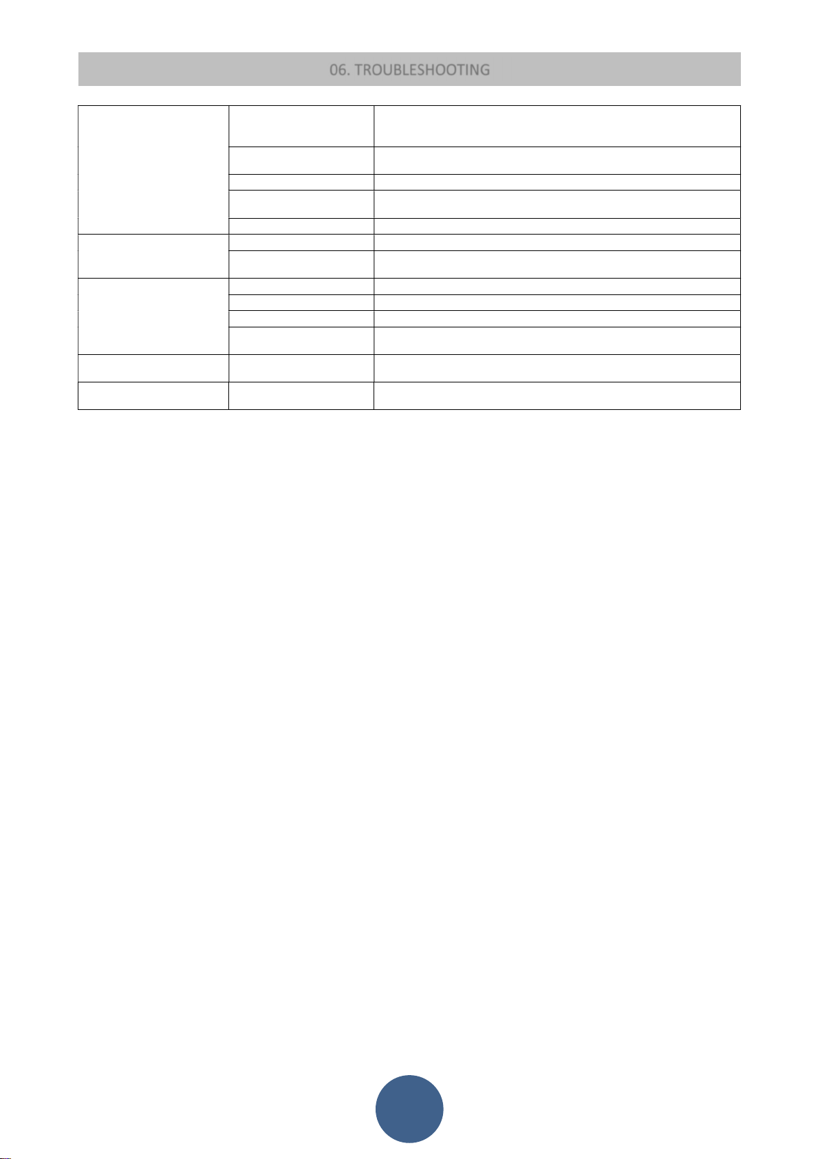
LET STOVE COOL DOWN,
LET STOVE COOL DOWN, MANUALLY RESET THERMOSTAT ON BACK. SWITCH
FAULTY THERMOSTAT WITH
FUME SENSOR
EXCESSIVE PELLET SET VALUE
RADIO
C
EMOTE CONTROL NOT
TRY DISCONNECTING FROM THE MAINS SUPPLY ANY HOUSEHOLD APPLIANCE
REMOTE CONTROL DOES NOT
ALARM SIC FIREBOX
OVERHEATING
ALARM FUME
SENSOR
ALARM HOT TEMP
06. TROUBLESHOOTING
MANUALLY RESET
THERMOSTAT ON BACK
TEMPORARY POWER OUTAGE
FAULTY EXCHANGER BLOWER CALL TECHNICAL ASSISTANCE.
RESET
FAULTY CONTROL BOARD CALL TECHNICAL ASSISTANCE.
FAULTY FUME SENSOR
DISCONNECTED
FAULTY FUME SENSOR
FAULTY CONTROL BOARD
FAULTY EXCHANGER BLOWER
AT MAXIMUM HEAT OUTPUT
LET STOVE COOL DOWN, MANUALLY RESET THERMOSTAT ON BACK. IF THE
PROBLEM REMAINS UNSOLVED, CONTACT A SPECIALISED TECHNICIAN.
STOVE ON AGAIN.
CALL TECHNICAL ASSISTANCE.
CALL TECHNICAL ASSISTANCE.
CALL TECHNICAL ASSISTANCE.
CALL TECHNICAL ASSISTANCE.
CALL TECHNICAL ASSISTANCE.
CALL TECHNICAL ASSISTANCE.
CALL TECHNICAL ASSISTANCE.
CONNECTING (FIELD SEARCH) POSSIBLE INTERFERENCE
SWITCH ON DISPLAY SWITCHED OFF
OR ANY OTHER APPLIANCE THAT MAY GENERATE ELECTROMAGNETIC FIELDS.
CHECK BATTERY / FAULTY REMOTE CONTROL.
32
Page 34

33
Page 35
07. CERTIFICATE OF INSTALLATION AND TESTING
CERTIFICATE OF INSTALLATION AND TESTING
CUSTOMER: __________________________
ROAD: ______________________________
CITY: ______________________________
POSTAL CODE: _________________________
PROVINCE: __________________________
TEL: _________________________________
Delivery date:______________________
Delivery date: ________________
Equipment mod.: _____________________
Serial number: Year:
Retailer's Stamp:
The customer acknowledges that, upon completion of the installation of the device, the works were carried out
professionally and in accordance with the instructions in this user manual. The same also states that they acknowledge
perfect functioning and are aware of the information needed to correctly use, operate and perform maintenance on the
appliance.
Signature of the CUSTOMER Signature of the RETAILER / INSTALLER
Installer's stamp:
First name: __________________________
Last Name: _________________________
Address: ___________________Postal code.:
Location: ___________________________
Tel:
-------------------------------------------------------------------------------------------------------------------------
Copy of the retailer or installer
CERTIFICATE OF INSTALLATION AND TESTING
CUSTOMER: _________________________
ROAD: ______________________________
CITY: ______________________________
POSTAL CODE: ________________________
PROVINCE: __________________________
TEL: _________________________________
Delivery date:______________________
Delivery date: ________________
Equipment mod.: _____________________
Serial number:
Year:
Retailer's Stamp:
The customer acknowledges that, upon completion of the installation of the device, the works were carried out
professionally and in accordance with the instructions in this user manual. The same also states that they acknowledge
perfect functioning and are aware of the information needed to correctly use, operate and perform maintenance on the
appliance.
Signature of the CUSTOMER Signature of the RETAILER / INSTALLER
Installer's stamp:
First name: ________________________
Last Name: _________________________
Address: ___________________Postal code.:
Location: ___________________________
Tel:
34
Page 36

35
Page 37

08. YEARLY SCHEDULED MAINTENANCE
Date 1st maintenance ____________ / ____________ /____________
(Technical Assistance Centre stamp)
Date 2nd maintenance ____________ / ____________ /____________
(Technical Assistance Centre stamp)
Date 3rd maintenance ____________ / ____________ /____________
(Technical Assistance Centre stamp)
36
Page 38

09. WARRANTY CERTIFICATE
Congratulations! Thank you for purchasing an Eva Stampaggi product.
Warranty
The warranty period is two years if fiscally described as sold to an individual (Legislative Decree no. 24 of 02.02.2002) and one year
if sold to a company or profession (subject to VAT).
The tax document referred to the product purchase gives validity to the warranty and the date on it shall be used to calculate the
warranty period.
The warranty provided shall be subject to the following terms and conditions:
You can contact the staff in charge of the after-sale procedure by calling 0438.35469 or by sending an e-mail to [email protected]
Our qualified staff will provide you with information concerning technical, installation or maintenance problems.
Should it prove impossible to solve the issue over the phone, our staff will forward it to the Technical Support Service closest to you,
which will guarantee assistance from a technician within five working days
Any parts replaced during the warranty period shall be covered for the remaining period of the purchased product warranty.
The manufacturer shall not pay the customer any indemnities for the inconvenience of not being able to use the product during the
period required for repairing.
Should it be necessary to replace the product, the manufacturer will deliver it to the retailer who will then deliver it to the end user
following the same procedure as for the product purchase.
This warranty is valid within Italy. Should the product be sold or installed abroad the warranty shall be recognised by the distributor
in charge of the relevant territory.
This warranty covers the repair or replacement of faulty parts or components or of the entire product at our sole discretion.
Whenever you require assistance, you may be asked to provide:
Serial number
Stove model
Purchase date
Purchase location
Warranty activation certificate filled in by an authorised Technical Assistance Centre
The warranty shall not cover:
Non-compliant installation or installation carried out by non-qualified staff (UNI10683 and UNI EN 1443);
Initial ignition not carried out by an authorised technician
Improper use, such as keeping the stove switched on for too long at maximum heat output;
Annual stove maintenance carried out by someone other than one of our authorised Technical Assistance Centres;
Vent pipe cleaning not carried out;
37
Page 39
09. WARRANTY CERTIFICATE
The warranty will not cover the following differences due to the natural features of the covering
materials:
Veining is a main feature of stone guaranteeing its uniqueness;
Any small cracks or cracking in ceramic or majolica surrounds;
Any shade or tone differences in ceramic or majolica surrounds;
Door glass;
Gaskets;
Ignition plug heating elements (the warranty period is 1 year);
The warranty does not cover masonry works;
Damage to chromed and/or anodised and/or painted metal parts or on any other treated surfaces due to rubbing or
bumping with other metal parts;
Damage to chromed and/or anodised and/or painted metal parts or on any other treated surfaces due to improper
maintenance and/or cleaning using chemical products or agents (said parts must be cleaned using only water);
Damage to mechanical components or parts due to improper use or to installation carried out by non-qualified staff or
not in compliance with the instructions provided with the product;
Damage to electrical or electronic parts or components due to improper use or to installation carried out by non-qualified
staff or not in compliance with the instructions provided with the product;
Attention: after purchase, please keep this warranty certificate together with the original
package, installation and testing certificate and the retailer receipt.
IMPORTANT:
EVA STAMPAGGI SRL RECOMMENDS CONTACTING ITS RETAILERS AND AUTHORISED ASSISTANCE CENTRES.
INSTALLATION IS OBLIGATORY BY LAW, EVA STAMPAGGI STRONGLY RECOMMENDS THE INITIAL IGNITION OF
PRODUCTS BY QUALIFIED TECHNICIANS. EVA STAMPAGGI IS NOT RESPONSIBLE FOR ONLINE SALES AND FOR
RELATED OFFERS AS IT DOES NOT OFFER DIRECT SALES TO THE PUBLIC. FOR ANY TECHNICAL ISSUES DURING
THE PERIOD OF LEGAL WARRANTY, THE PROCEDURE REQUIRES CONTACTING OF THE RETAILER OR DIRECTLY
OF OUR AFTER SALES.
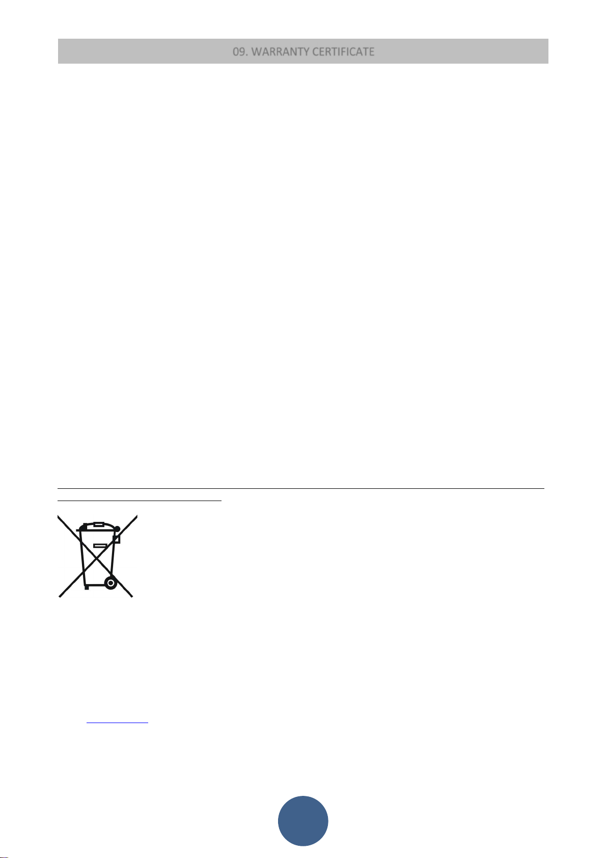
WARNINGS for correct disposal of waste electrical and electronic equipment (WEEE) in accordance with EC Directive 2002/96/EC
and subsequent amendment 2003/108/CE.
Application of this symbol on the product determines that it is NOT waste that can be considered generic but should be
demolished and disposed of in compliance with the regulations in force in the country of use, making sure that the special
collection centres are legally compliant both in relation to safety and in terms of respecting and protecting the
environment. Responsibility for such disposal is borne by the owner and to avoid incurring penalties or negative
consequences for the environment and health, we advise directly contacting the municipal authorities, the local authority
for waste disposal or the retailer, to learn more about the places and ways of collection.
The correct disposal of waste is important not only for the environment and for the health of citizens but also because
this operation involves the recovery of materials with consequent important savings of energy and resources.
Eva Stampaggi S.r.l. Retailer Stamp and Signature
Via Cal Longa Z.I.
I - 31028 Vazzola (Treviso - Italy)
Tel. +39.0438.740433 rollover lines
Fax +39.0438.740821
E-Mail: [email protected]
38
 Loading...