

Page 1

Part No. 2017361062
Quick Reference Guide
EES-3610 Series
VIA Eden Micro PC
2st Ed. – 5 May 2004
Page 2

EES-3610
EES-3610 Quick Reference Guide
2
FCC STATEMENT
THIS DEVICE COMPLIES WITH PART 15 FCC RULES. OPERATION IS SUBJECT TO
THE FOLLOWING TWO CONDITIONS:
(1) THIS DEVICE MAY NOT CAUSE HARMFUL INTERFERENCE.
(2) THIS DEVICE MUST ACCEPT ANY INTERFERENCE
RECEIVED INCLUDING INTERFERENCE THAT MAY CAUSE UNDESIRED
OPERATION.
THIS EQUIPMENT HAS BEEN TESTED AND FOUND TO COMPLY WITH THE LIMITS
FOR A CLASS "A" DIGITAL DEVICE, PURSUANT TO PART 15 OF THE FCC RULES.
THESE LIMITS ARE DESIGNED TO PROVIDE REASONABLE PROTECTION AGAINTST
HARMFUL INTERFERENCE WHEN THE EQUIPMENT IS OPERATED IN A
COMMERCIAL ENVIRONMENT. THIS EQUIPMENT GENERATES, USES, AND CAN
RADIATE RADIO FREQUENCY ENERGY AND, IF NOT INSTATLLED AND USED IN
ACCORDANCE WITH THE INSTRUCTION MANUAL, MAY CAUSE HARMFUL
INTERFERENCE TO RADIO COMMUNICATIONS.
OPERATION OF THIS EQUIPMENT IN A RESIDENTIAL AREA IS LIKELY TO CAUSE
HARMFUL INTERFERENCE IN WHICH CASE THE USER WILL BE REQUIRED TO
CORRECT THE INTERFERENCE AT HIS OWN EXPENSE.
Page 3

Quick Reference Guide
EES-3610 Quick Reference Guide
3
Notice:
This guide is designed for experienced users to setup the system within the shortest time.
For detailed information, please always refer to the electronic user's manual.
Copyright Notice
Copyright 2003 Evalue Technology Inc., ALL RIGHTS RESERVED.
No part of this document may be reproduced, copied, translated, or transmitted in any form
or by any means, electronic or mechanical, for any purpose, without the prior written
permission of the original manufacturer.
Trademark Acknowledgement
Brand and product names are trademarks or registered trademarks of their respective
owners.
Disclaimer
Evalue Technology Inc. reserves the right to make changes, without notice, to any product,
including circuits and/or software described or contained in this manual in order to improve
design and/or performance. Evalue Technology assumes no responsibility or liability for the
use of the described product(s), conveys no license or title under any patent, copyright, or
mask work rights to these products, and makes no representations or warranties that these
products are free from patent, copyright, or mask work right infringement, unless otherwise
specified. Applications that are described in this manual are for illustration purposes only.
Evalue Technology Inc. makes no representation or warranty that such application will be
suitable for the specified use without further testing or modification.
Page 4

EES-3610
EES-3610 Quick Reference Guide
4
Life Support Policy
Evalue Technology’s PRODUCTS ARE NOT FOR USE AS CRITICAL COMPONENTS IN
LIFE SUPPORT DEVICES OR SYSTEMS WITHOUT THE PRIOR WRITTEN APPROVAL
OF Evalue Technology Inc.
As used herein:
1. Life support devices or systems are devices or systems which, (a) are intended for
surgical implant into body, or (b) support or sustain life and whose failure to perform,
when properly used in accordance with instructions for use provided in the labeling, can
be reasonably expected to result in significant injury to the user.
2. A critical component is any component of a life support device or system whose failure to
perform can be reasonably expected to cause the failure of the life support device or
system, or to affect its safety or effectiveness.
A Message to the Customer
Evalue Customer Services
Each and every Evalue’s product is built to the most exacting specifications to ensure
reliable performance in the harsh and demanding conditions typical of industrial
environments. Whether your new Evalue device is destined for the laboratory or the factory
floor, you can be assured that your product will provide the reliability and ease of operation
for which the name Evalue has come to be known.
Your satisfaction is our primary concern. Here is a guide to Evalue’s customer services. To
ensure you get the full benefit of our services, please follow the instructions below carefully.
Page 5

Quick Reference Guide
EES-3610 Quick Reference Guide
5
Technical Support
We want you to get the maximum performance from your products. So if you run into
technical difficulties, we are here to help. For the most frequently asked questions, you can
easily find answers in your product documentation. These answers are normally a lot more
detailed than the ones we can give over the phone. So please consult the user’s manual
first.
To receive the latest version of the user’s manual, please visit our Web site at:
http://www.evalue-tech.com/
If you still cannot find the answer, gather all the information or questions that apply to your
problem, and with the product close at hand, call your dealer. Our dealers are well trained
and ready to give you the support you need to get the most from your Evalue’s products. In
fact, most problems reported are minor and are able to be easily solved over the phone.
In addition, free technical support is available from Evalue’s engineers every business day.
We are always ready to give advice on application requirements or specific information on
the installation and operation of any of our products. Please do not hesitate to call or e-mail
us.
Headquarters
Evalue Technology Inc.
7F, 228, Lian-cheng Road,
Chung-ho City, Taipei,
Taiwan
Tel: +886-2-82262345
Fax: +886-2-82262777
http://www.evalue-tech.com
E-mail: [email protected]
Europe Branch Office
Evalue Europe A/S
Nordre Strandvej 119C,
3150 Hellebaek,
Denmark
Tel : +45-7025-0310
Fax : +45-4975-5026
http://www.evalue-tech.com
E-mail: [email protected]
China Branch Office
Evalue Technology Shanghai Inc.
Room 909, 9F, Section B, No.900,
Yisan Road, Caohejing Hi-tech Park,
Shanghai 200233, China
Tel : +86-21-5423-4170
Fax : +86-21-5423-4171
http://www.evalue-tech.com
E-mail: [email protected]
US Branch Office
Evalue Technology Inc.
Suite 210, 200 Tornillo Way,
Tinton Falls, NJ 07712
USA
Tel: +1-732-578-0200
Fax: +1-732-578-0250
http://www.evalue-tech.com
E-mail: [email protected]
Page 6

EES-3610
EES-3610 Quick Reference Guide
6
Product Warranty
Evalue warrants to you, the original purchaser, that each of its products will be free from
defects in materials and workmanship for two years from the date of purchase.
This warranty does not apply to any products which have been repaired or altered by
persons other than repair personnel authorized by Evalue, or which have been subject to
misuse, abuse, accident or improper installation. Evalue assumes no liability under the
terms of this warranty as a consequence of such events. Because of Evalue’s high
quality-control standards and rigorous testing, most of our customers never need to use our
repair service. If an y of Evalue’s products is defective, it will be repaired or replaced at no
charge during the warranty period. For out-of-warranty repairs, you will be billed according
to the cost of replacement materials, service time, and freight. Please consult your dealer
for more details. If you think you have a defective product, follow these steps:
1. Collect all the information about the problem encountered. (For example, CPU type and
speed, Evalue’s products model name, hardware & BIOS revision number, other
hardware and software used, etc.) Note anything abnormal and list any on-screen
messages you get when the problem occurs.
2. Call your dealer and describe the problem. Please have your manual, product, and any
helpful information available.
3. If your product is diagnosed as defective, obtain an RMA (return material authorization)
number from your dealer. This allows us to process your good return more quickly.
4. Carefully pack the defective product, a complete Repair and Replacement Order Card
and a photocopy proof of purchase date (such as your sales receipt) in a shippable
container. A product returned without proof of the purchase date is not eligible for
warranty service.
5. Write the RMA number visibly on the outside of the package and ship it prepaid to your
dealer.
Page 7

Quick Reference Guide
EES-3610 Quick Reference Guide
7
Packing List
Before you begin installing your Micro PC, please make sure that the following materials
have been shipped:
n 1 EES-3610 VIA Eden Micro PC (with ECM-3610 inside)
n 1 Quick Reference Guide
n 1 CD-ROM contains the followings:
— User’s Manual in PDF format
— Ethernet driver and utilities
— VGA drivers and utilities
— Audio drivers and utilities
n Cable set includes the followings:
— 1 PS/2 keyboard and mouse Y cable (6-pin, Mini-DIN)
— 1 IDE HDD cable (44-pin, pitch 2.0mm)
— 1 AC to DC adapter
— Power Cord
If any of these items are missing or damaged, please contact your distributor or sales
representative immediately.
Page 8

EES-3610
EES-3610 Quick Reference Guide
8
1. Safety Precautions
1.1 Warning!
Always completely disconnect the power cord from your chassis whenever
you work with the hardware. Do not make connections while the power is on.
Sensitive electronic components can be damaged by sudden power surges.
Only experienced electronics personnel should open the PC chassis.
1.2 Caution!
Always ground yourself to remove any static charge before touching the
CPU card. Modern electronic devices are very sensitive to static electric
charges. As a safety precaution, use a grounding wrist strap at all times.
Place all electronic components in a static-dissipative surface or
static-shielded bag when they are not in the chassis.
Page 9

Quick Reference Guide
EES-3610 Quick Reference Guide
9
2. Specifications
n Palm size (220 x 147 x 65 mm)
n VIA Eden series CPU Board
n Rugged Aluminum Alloy Chassis w/ 2.5" HDD Mounting Kit
n Dual RJ-45 10/100Base-Tx Interfaces (EES-3610 only, optional Intel LAN chips)
n DB-15 VGA Interface
n Mic-In / Line-In / Line-Out Audio Jacks
n CF+ Type I/II Socket with Ejector
n 2 COMs / 2 USB / 1 Parallel Port
n AC input: 90 ~264; VAC/47~63 Hz
n DC output: 5 VDC +/- 5% rated at 5 A with I peak rated at 6.0 A
n AC plug: IEC 320, 3 Blades (desk-top type)
n DC plug: 3Ft with 5.5*2.1*9.5 mm
n Adapter size: 121(L)*61(W)*35(H) mm
n Adapter safety approvals: UL, CUL, TUV, CE
Page 10
EES-3610
EES-3610 Quick Reference Guide
10
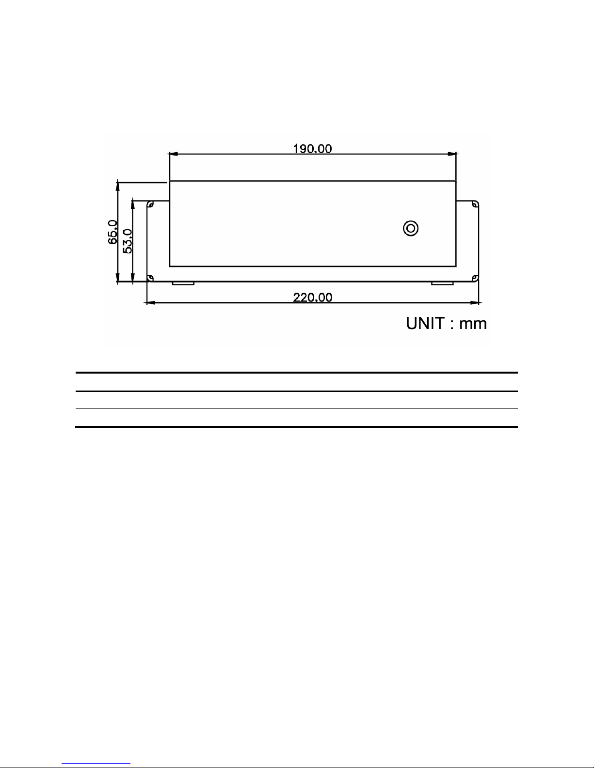
3. System Overview
3.1 Front Panel
Label Function Note
Power OFF/ON
System Power Switch
LED
System Power Indicator
Page 11
Quick Reference Guide
EES-3610 Quick Reference Guide
11
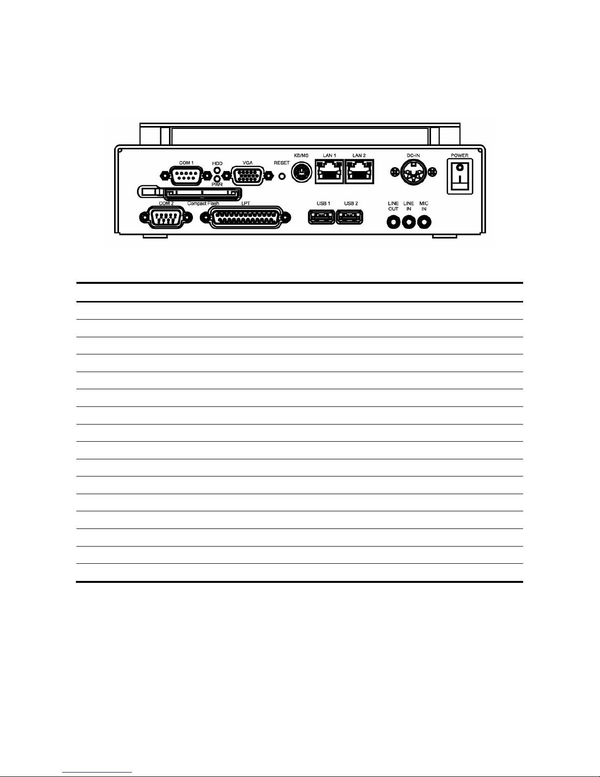
3.2 Rear Panel
Label Function Note
Compact Flash
CF+ Type I/II Socket with Ejector
COM1
Serial Port 1 DB-9 male connector
COM2
Serial Port 2 DB-9 male connector
DC-IN
DC Power-in Plug 5.5*2.1*9.5 mm
HDD
HDD Activity Indicator
KB/MS
Keyboard and PS/2 mouse connector 6-pin mini DIN
LAN1
10/100Base-Tx Ethernet 1 connector RJ-45
LAN2
10/100Base-Tx Ethernet 2 connector RJ-45 (EES-3610 only)
LINE OUT
Line-out Audio Jack
LINE IN
Line-in Audio Jack
MIC IN
Mic-in Audio Jack
PRINT
Printer Port DB-25 male connector
PWR
System Power Indicator
RESET
Reset Button
USB
Universal Serial Bus Connectors
VGA
CRT Connector DB-15 male connector
Page 12

EES-3610
EES-3610 Quick Reference Guide
12
4. Hardware Configuration for ECM-3610 Micro Module
4.1 Installation Procedure
1. Unplug the power adapter from EES-3610.
2. Make sure all external cables are unattached.
3. Unscrew the front panel.
4. Disassemble the top cover for HDD installation, or
5. Disassemble the bottom cover for memory and/or CF card installation.
4.2 Installing DRAM (SODIMM)
4.2.1 System Memory
The reverse side of the ECM-3610 contains a socket for 144-pin dual inline memory
module (SODIMM). The socket uses 3.3 V unbuffered synchronous DRAM (SDRAM).
SODIMM module is available in capacities of 32, 64, 128, or 256 MB. The socket can be
filled in the SODIMM of any size, giving your ECM-3610 single board between 32 and 256
MB of memory.
4.2.2 Supplementary Information About SODIMM
Your ECM-3610 accepts both regular and PC-100 SDRAM SODIMM Module (with or
without parity). Single-sided modules are typically 64 MB; double-sided modules are
usually 32 or 128 MB.
4.2.3 Memory Installation Procedures
Press the SODIMM module right down into the socket, until you hear a click. This is when
the two handles have automatically locked the memory module into the correct position of
the SODIMM socket. (See Figure below) To take away the memory module, just push both
handles outward, and the memory module will be ejected by the mechanism in the socket.
Page 13
Quick Reference Guide
EES-3610 Quick Reference Guide
13
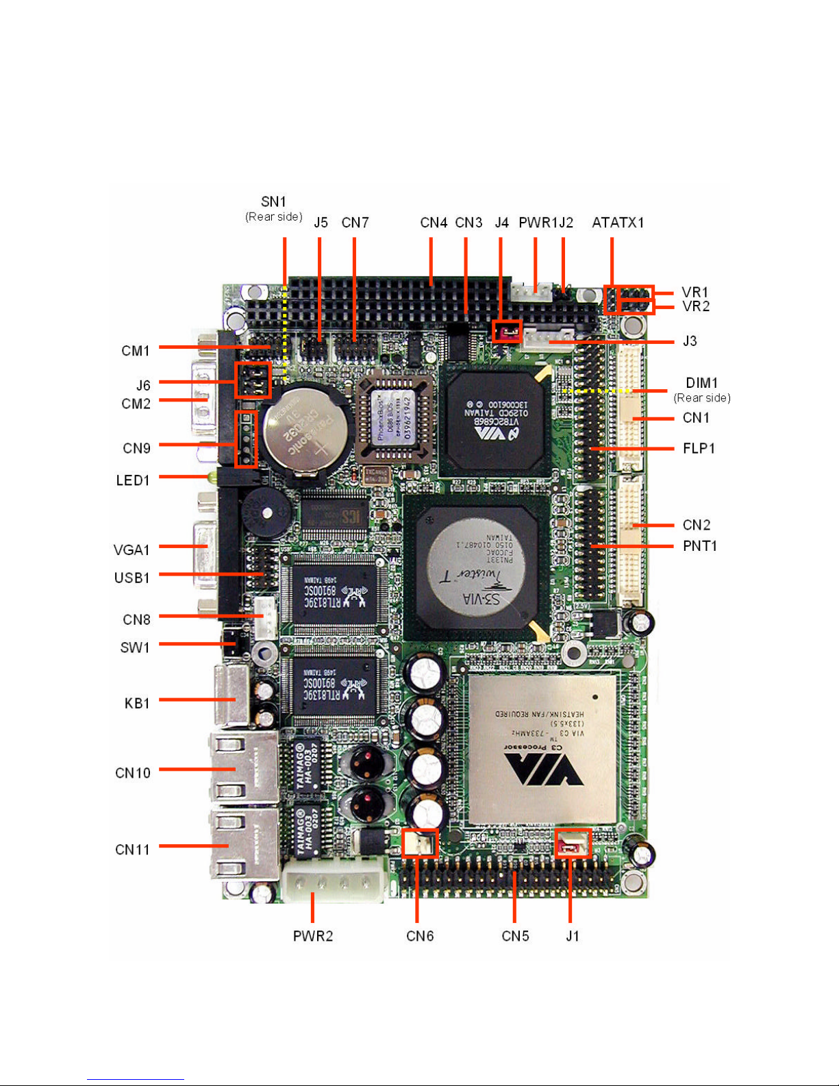
4.3 Jumper & Connector
4.3.1 Jumper & Connector Layout
Page 14

EES-3610
EES-3610 Quick Reference Guide
14
4.3.2 Jumper & Connector List
Connectors on the board are linked to external devices such as hard disk drives, keyboard,
mouse, or floppy drives. In addition, the board has a number of jumpers that allow you to
configure your system to suit your application.
The following tables list the function of each of the board's jumpers and connectors.
Jumpers
Label Function Note
J4
Clear CMOS 3 x 1 header, pitch 2.54mm
J5, J6
COM2 RS-232/422/485 select 3 x 2 header, pitch 2.0mm
4 x 3 header, pitch 2.0mm (J6)
ATATX1
AT / ATX power select 3 x 1 header, pitch 2.0mm
Page 15

Quick Reference Guide
EES-3610 Quick Reference Guide
15
Connectors
Label Function Note
CM1
Serial port 2 connector 5 x 2 header, pitch 2.0mm
CM2
Serial port 1 connector DB-9 male connector
CN1
Secondary LCD panel connector HIROSE DF13-40DP-1.25V
CN2
Primary LCD panel connector HIROSE DF13-40DP-1.25V
CN3, CN4
PC/104 connector
CN5
IDE connector 20 x 2 header, pitch 2.54mm
CN6
CPU fan connector 2 x 1 wafer, pitch 2.54mm
CN7
Audio connector 5 x 2 header, pitch 2.0mm
CN8
CD-ROM audio input connector 4 x 1 wafer, pitch 2.0mm
CN9
IrDA connector 5 x 1 header, pitch 2.0mm
CN10 (LAN1)
10/100Base-Tx Ethernet 1 connector RJ-45
CN11 (LAN2)
10/100Base-Tx Ethernet 2 connector RJ-45 (EES-3610 only)
DIM1
144-pin SODIMM socket (Rear side)
FLP1
Floppy connector 17 x 2 header, pitch 2.0mm
J1
ATX Power connector 3 x 1 wafer, pitch 2.54mm
J2
ATX Soft-power bottom 2 x 1 header, pitch 2.54mm
J3
LCD inverter connector 5 x 1 wafer, pitch 2.0mm
KB1
Keyboard and PS/2 mouse connector 6-pin mini DIN
PNT1
Parallel port connector 13 x 2 header, pitch 2.0mm
PWR1
Auxiliary power connector 4 x 1 wafer, pitch 2.0mm
PWR2
Power connector Molex A-8981-04V5
SN1
Compact Flash connector (Rear side)
SW1
Reset button
USB1
USB connector 5 x 2 header, pitch 2.0mm
VGA1
CRT connector DB-15 female connector
VR1
LCD backlight brightness adjustment
connector
3 x 1 header, pitch 2.54mm
VR2
STN LCD contrast adjustment connector 3 x 1 header, pitch 2.54mm
Page 16
EES-3610
EES-3610 Quick Reference Guide
16
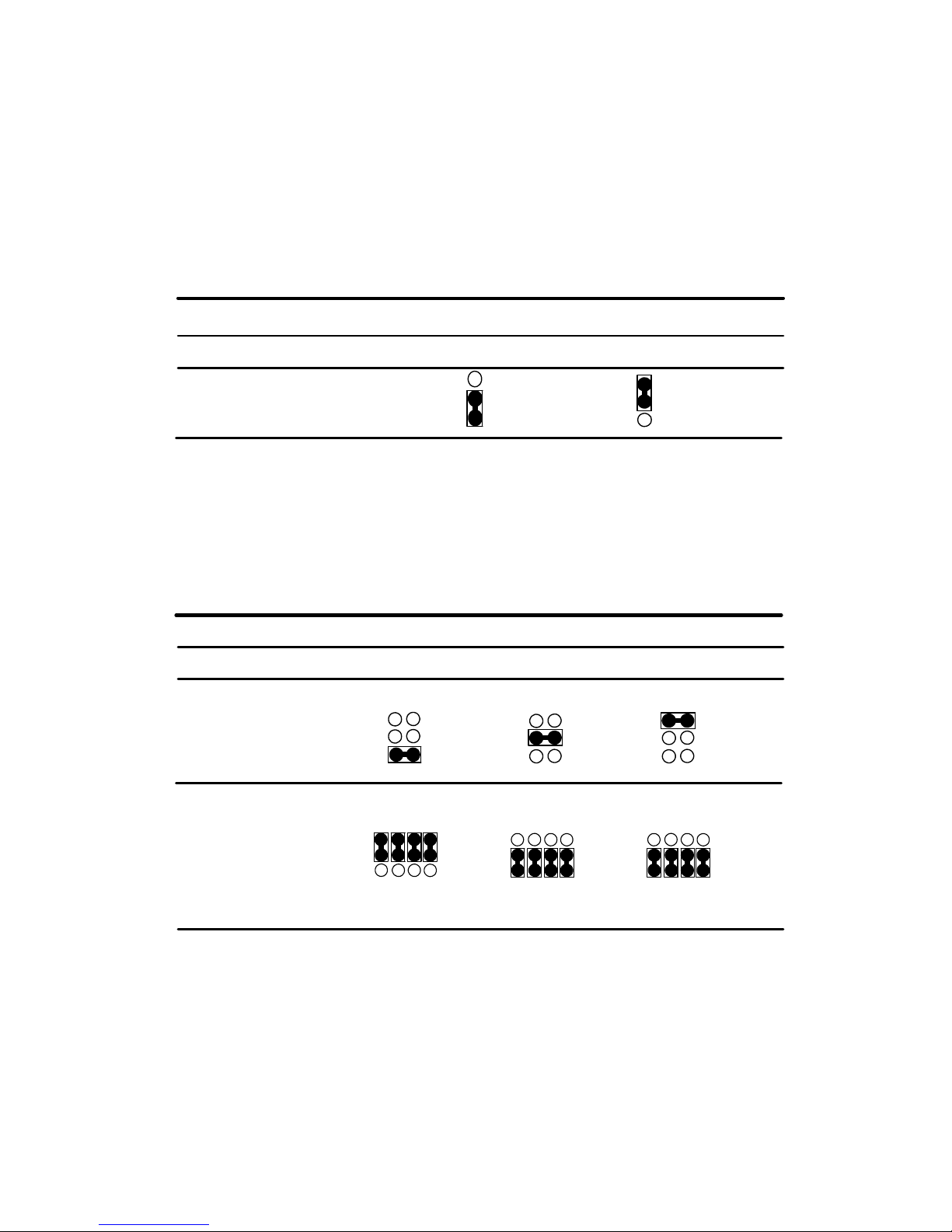
4.4 Jumper Settings
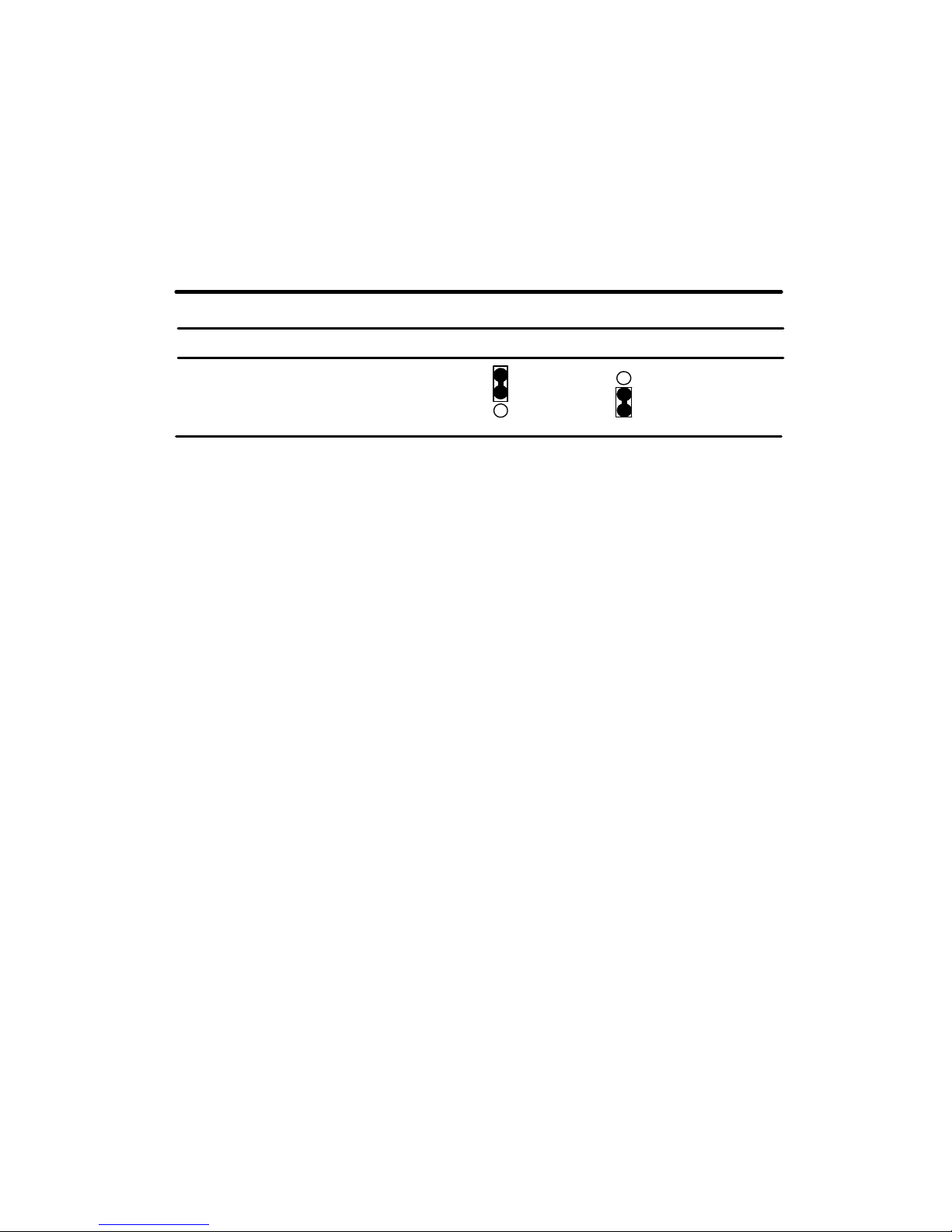
4.4.1 Clear CMOS (J4)
You can use J4 to clear the CMOS data if necessary. To reset the CMOS data, set
J4 to 2-3 closed for just a few seconds, and then move the jumper back to 1-2
closed.
Clear CMOS (J4)
Clear CMOS Protect*
* default
4.4.2 COM2 RS-232/422/485 Select (J5, J6)
The ECM-3610 COM2 serial port can be selected as RS-232, RS-422, or RS-485
by setting J5 & J6.
COM2 RS-232/422/485 Select (J5, J6)
RS-232* RS-422 RS-485
* default
6 4 2
5
3
1
J5
6 4 2
5
3
1
6 4 2
5
3
1
J6
J4
1
2
3
1
2
3
1 4 7 10
3 6 9 12
1 4 7 10
3 6 9 12
1 4 7 10
3 6 9 12
Page 17
Quick Reference Guide
EES-3610 Quick Reference Guide
17
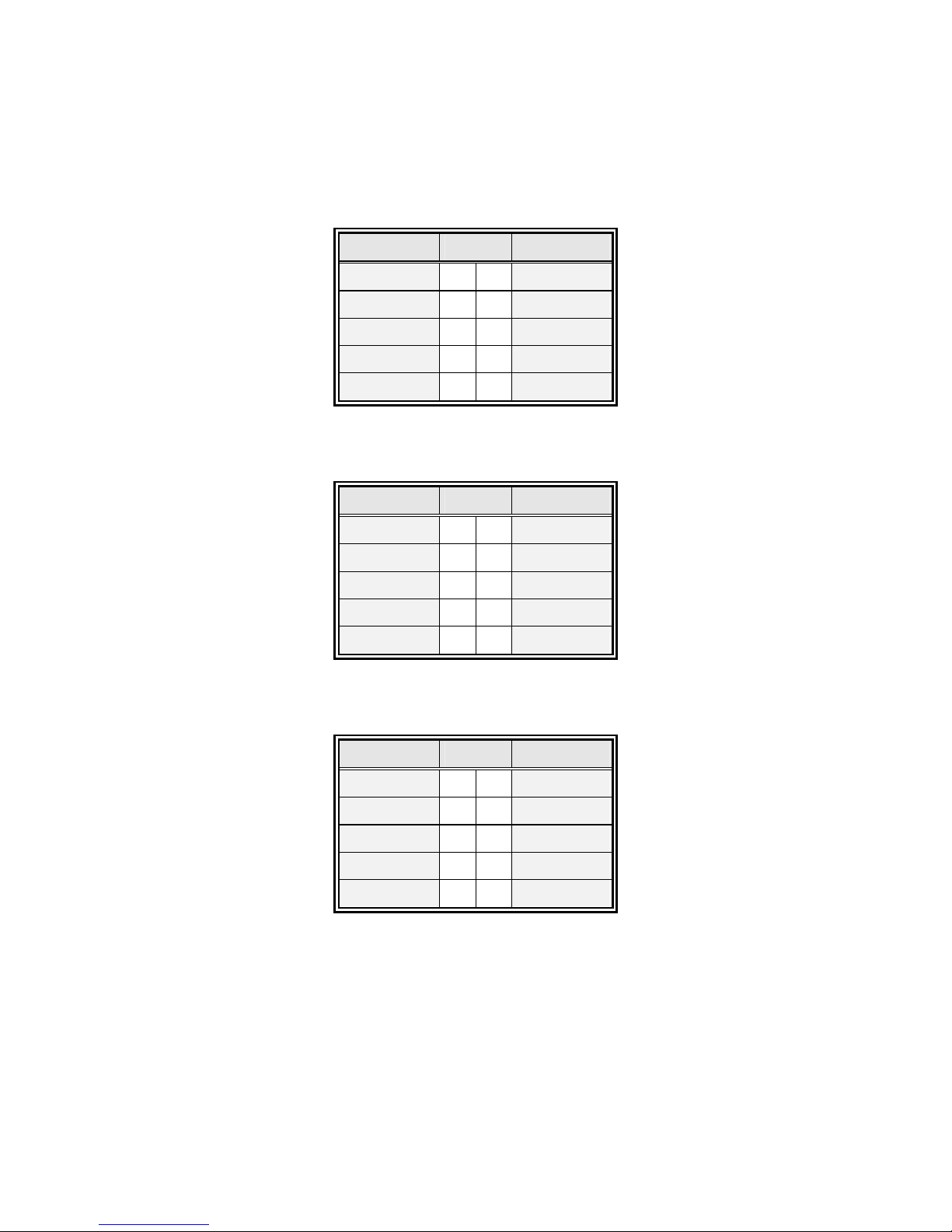
4.4.3 AT/ATX Power Select (ATATX1)
You can use ATATX1 to select the power supply type. To use the AT power supply,
set ATATX1 to 1-2 closed. Set ATATX1 to 2-3 closed, if ATX power supply is to be
used.
AT/ATX Power Select (ATATX1)
AT P/S* ATX P/S
* default
Note:
Set J1 to 2-3 closed, if AT power supply is to be used.
1
2
3
ATATX1
1
2
3
Page 18
EES-3610
EES-3610 Quick Reference Guide
18
4.5 Connector Definitions
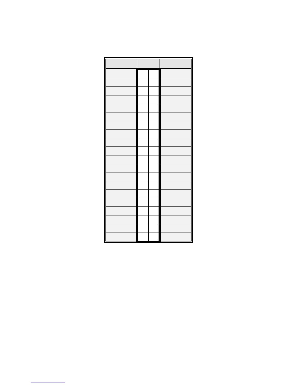
4.5.1 Pin Header Serial Port 2 Connector in RS-232 Mode (CM1)
Signal PIN Signal
NC 10 9 RI
CTS 8 7 RTS
DSR 6 5 GND
DTR 4 3 TxD
RxD 2 1 DCD
4.5.2 Pin Header Serial Port 2 Connector in RS-422 Mode (CM1)
Signal PIN Signal
NC 10 9 NC
NC 8 7 NC
NC 6 5 NC
Rx- 4 3 Tx+
Rx+ 2 1 Tx-
4.5.3 Pin Header Serial Port 2 Connector in RS-485 Mode (CM1)
Signal PIN Signal
NC 10 9 NC
NC 8 7 NC
NC 6 5 NC
NC 4 3 DATA+
NC 2 1 DATA-
Page 19
Quick Reference Guide
EES-3610 Quick Reference Guide
19
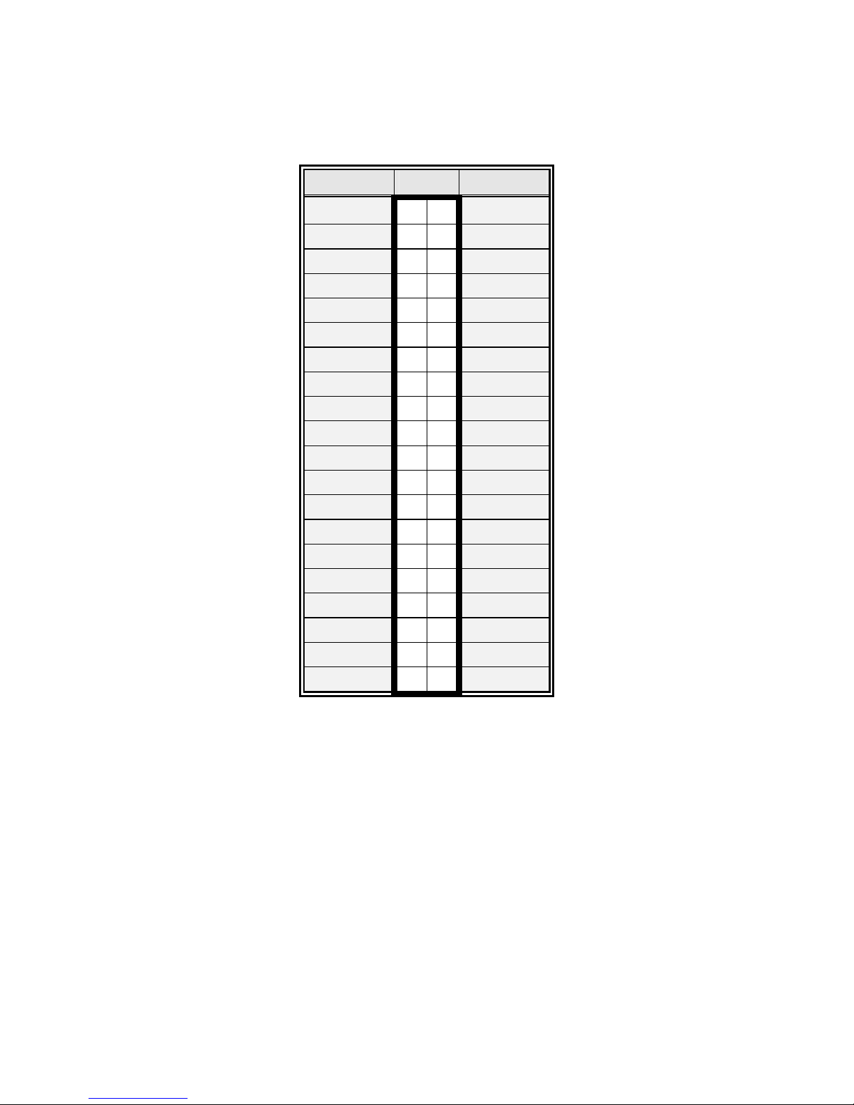
4.5.4 Secondary LCD Panel Connector (CN1)
Signal PIN Signal
5V 2 1
5V
GND 4 3
GND
3.3V 6 5
3.3V
GND 8 7
Vcon
P25 10 9
P24
P27 12 1 1
P26
P29 14 13
P28
P31 16 15
P30
P33 18 17
P32
P35 20 19
P34
GND 22 21
GND
Y2M 24 23
Y2P
Z1M 26 25
Z1P
ZCM 28 27
ZCP
Z0M 30 29
Z0P
YCM 32 31
YCP
GND 34 33
GND
Y0M 36 35
Y0P
Z2M 38 37
Z2P
Y1M 40 39
Y1P
Page 20
EES-3610
EES-3610 Quick Reference Guide
20
4.5.4.1 Primary LCD Panel Connector (CN2)
Signal PIN Signal
5V 2 1
5V
GND 4 3
GND
3.3V 6 5
3.3V
GND 8 7
Vcon
P1 10 9
P0
P3 12 1 1
P2
P5 14 13
P4
P7 16 15
P6
P9 18 17
P8
P11 20 19
P10
P13 22 21
P12
P15 24 23
P14
P17 26 25
P16
P19 28 27
P18
P21 30 29
P20
P23 32 31
P22
GND 34 33
GND
FLM 36 35
SHFCLK
LP 38 37
M
ENVEE 40 39
ENBKL
Page 21

Quick Reference Guide
EES-3610 Quick Reference Guide
21
4.5.5 Signal Description – Primary & Secondary LCD Panel Connector (CN2, CN1)
P [35:0] Flat Panel Data Bit 35 to Bit 0 for panel implementation.
SHFCLK Shift Clock. Pixel clock for flat panel data
LP Latch Pulse. Flat panel equivalent of HSYNC (horizontal synchronization)
FLM First Line Marker. Flat panel equivalent of VSYNC (vertical synchronization)
M Multipurpose signal, function depends on panel type. May be used as AC drive control
signal or as BLANK# or Display Enable signal
ENBKL Enable backlight signal. This signal is controlled as a part of the panel power sequencing
ENVEE Enable VEE. Signal to control the panel power-on/off sequencing. A high level may turn on
the VEE (LCD bias voltage) supply to the panel
Y[2:0]P, Z[2:0]P 1st & 2nd Channel Positive LVDS differential data output
Y[2:0]M, Z[2:0]M 1st & 2nd Channel Negative LVDS differential data output
YCP, ZCP 1st & 2nd Channel Positive LVDS differential clock output
YCM, ZCM 1st & 2nd Channel Negative LVDS differential clock output
Page 22

EES-3610
EES-3610 Quick Reference Guide
22
4.5.6 Signal Configuration – DSTN Displays
STN DSTN
Pin name 8-bit 16-bit 24-bit 8-bit 16-bit 24-bit 16-bit 24-bit
P35
P34
P33
P32 UG2 UG2
P31
P30 UR2 UR2
P29 UB3
P28 UB1 UB1
P27
P26 UG1 UG1
P25 UG3
P24 UR1 UR1 UR1
P23 B7 UR0 UR0
P22 G7 UB0 UB0 UB0 UR1 UR1
P21 R7 UR2 UR2
P20 B6 UG0 UG0 UG0 UR3
P19 G6 UR3 LR0 LR0
P18 R6 UR0 UR0 UR0 LR1 LR1
P17 B5 LR2 LR2
P16 G5 LR3
P15 R5 R5 UG0 UG0
P14 B4 B4 LG2 LG2 UG1 UG1
P13 G4 G4 LB3 UG2 UG2
P12 R4 R4 LR2 LR2 UG3
P11 B3 B3 LG0 LG0
P10 G3 G3 LB1 LB1 LG1 LG1
P9 R3 R3 LG2 LG2
P8 B2 B2 LG1 LG1 LG3
P7 G2 G2 G2 LG3 UB0 UB0
P6 R2 R2 R2 LR1 LR1 LR1 UB1 UB1
P5 B1 B1 B1 UB2
P4 G1 G1 G1 LB0 LB0 LB0 UB3
P3 R1 R1 R1 LB0 LB0
P2 B0 B0 B0 LG0 LG0 LG0 LB1 LB1
P1 G0 G0 G0 LR3 LB2
P0 R0 R0 R0 LR0 LR0 LR0 LB3
Page 23

Quick Reference Guide
EES-3610 Quick Reference Guide
23
4.5.7 Signal Configuration – TFT Displays
TFT
Pin name 9-bit 9-bit x 2
12-bit 12-bit x 2 15-bit 15-bit x 2 18-bit 18-bit x 2 24-bit
P35 B12 B13 B14 B15
P34 B2 B02 B3 B03 B4 B04 B14
P33 B11 B12 B13 B13
P32 B1 B01 B2 B02 B3 B03 B12
P31 B10 B11 B12 B11
P30 B0 B00 B1 B01 B2 B02 B10
P29 B10 B11 G15
P28 B0 B00 B1 B01 G14
P27 B10 G13
P26 B0 B00 G12
P25 G11
P24 G10
P23 G12 G13 G14 R5 R05 R7
P22 G2 G02 G3 G03 G4 G04 R4 R04 R6
P21 G11 G12 G13 R3 R03 R5
P20 G1 G01 G2 G02 G3 G03 R2 R02 R4
P19 G10 G11 G12 R1 R01 R3
P18 G0 G00 G1 G01 G2 G02 R0 R00 R2
P17 G10 G11 R11 R1
P16 G0 G00 G1 G01 R10 R0
P15 G10 G5 G05 G7
P14 G0 G00 G4 G04 G6
P13 G3 G03 G5
P12 G2 G02 G4
P11 R12 R13 R14 G1 G01 G3
P10 R2 R02 R3 R03 R4 R04 G0 G00 G2
P9 R11 R12 R13 R13 G1
P8 R1 R01 R2 R02 R3 R03 R12 G0
P7 R10 R11 R12 B5 B05 B7
P6 R0 R00 R1 R01 R2 R02 B4 B04 B6
P5 R10 R11 B3 B03 B5
P4 R0 R00 R1 R01 B2 B02 B4
P3 R10 B1 B01 B3
P2 R0 R00 B0 B00 B2
P1 R15 B1
P0 R14 B0
Note:
The principle of attachment of TFT panels is that the bits for red, green, and blue use
the most significant bits and skip the least significant bits if the display interface width
of the TFT panel is insufficient.
Page 24
EES-3610
EES-3610 Quick Reference Guide
24
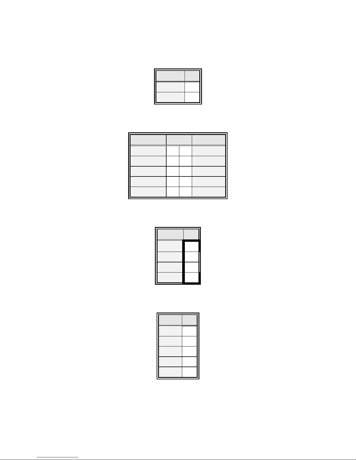
4.5.8 CPU Fan Connector (CN6)
Signal PIN
VCC 2
GND 1
4.5.9 Audio Connector (CN7)
Signal PIN Signal
NC 10 9
NC
Mic Bias 8 7
Mic-In
Line-In L 6 5 Line-In R
GND 4 3
GND
Line-Out L 2 1 Line-Out R
4.5.10 CD-ROM Audio Input Connector (CN8)
Signal PIN
CD_GND 1
CD_L 2
CD_GND 3
CD_R 4
4.5.11 IrDA Connector (CN9)
Signal PIN
VCC 1
NC 2
IRRX 3
GND 4
IRTX 5
Page 25
Quick Reference Guide
EES-3610 Quick Reference Guide
25
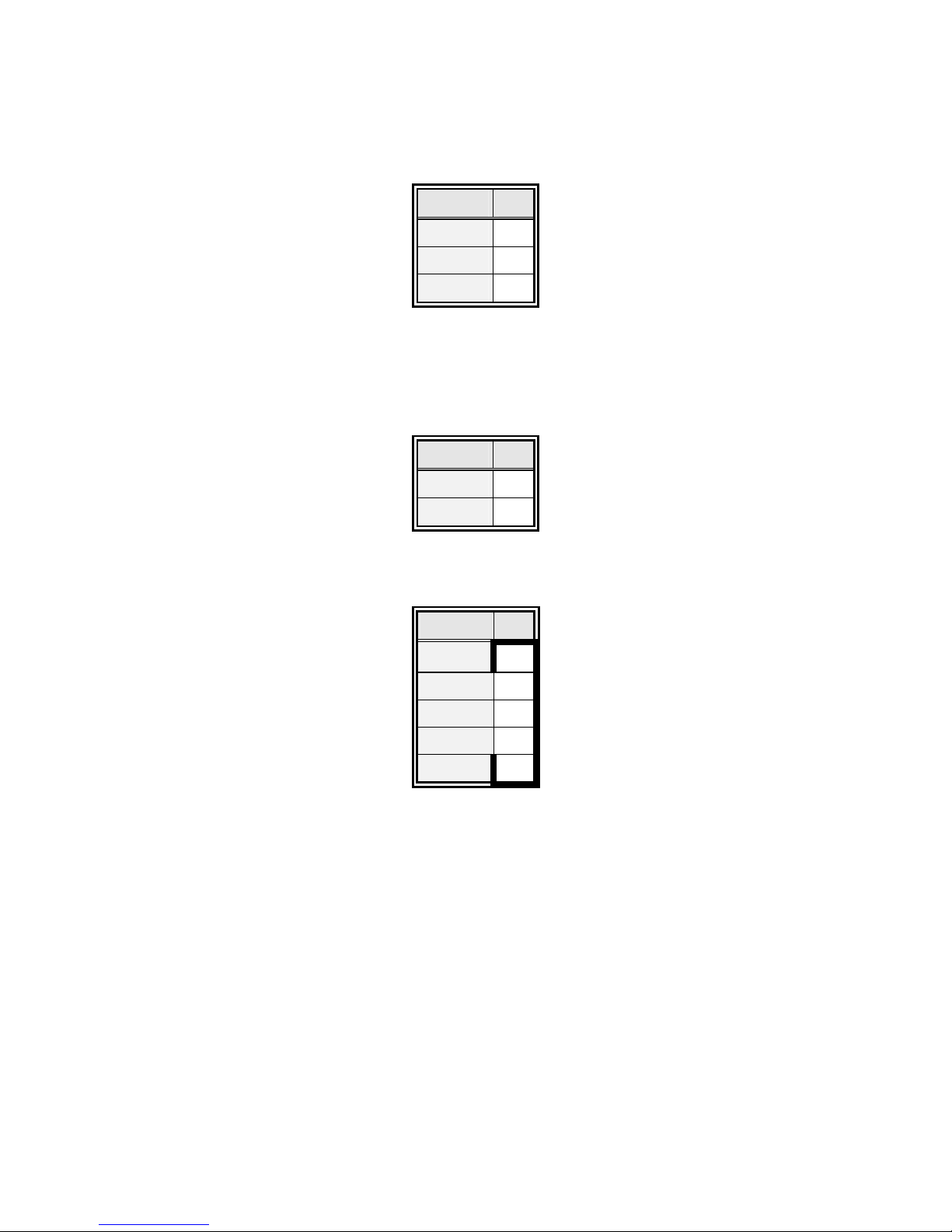
4.5.12 ATX Power Connector (J1)
Signal PIN
PS_ON 1
VCC 2
VCC_SB 3
Note:
Set J1 to 2-3 closed, if AT power supply is to be used.
4.5.13 ATX Soft-power Connector (J2)
Signal PIN
PWRBTN 1
GND 2
4.5.14 LCD Inverter Connector (J3)
Signal PIN
VCC 5
VR 4
ENBKL 3
GND 2
+12V 1
Note:
For inverters with adjustable Backlight function, it is possible to control the
LCD brightness through the VR signal (pin 4) controlled by VR1. Please see
the VR1 section for detailed circuitry information.
Page 26
EES-3610
EES-3610 Quick Reference Guide
26
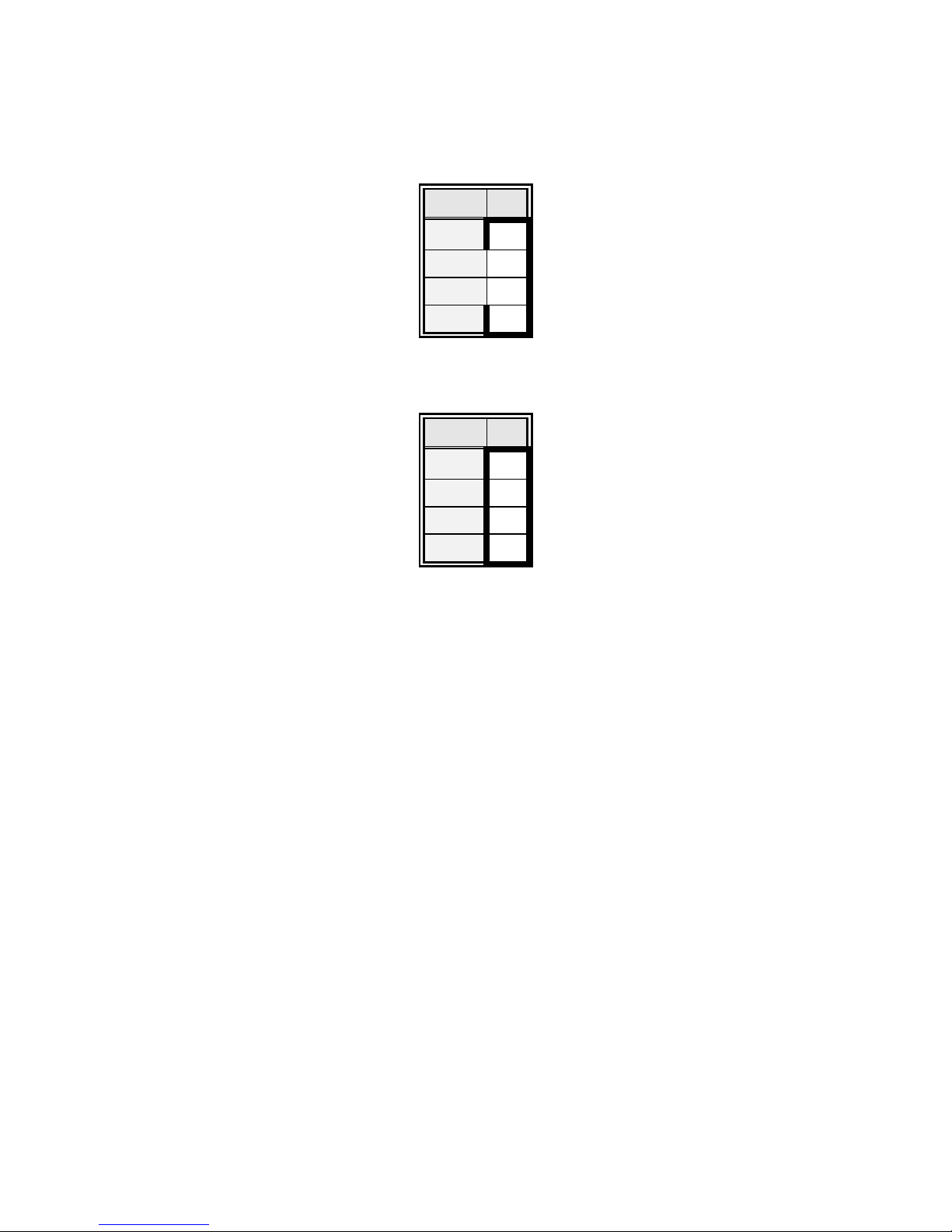
4.5.15 Auxiliary Power Connector (PWR1)
Signal PIN
-12v 4
GND 3
GND 2
-5V 1
4.5.16 Power Connector (PWR2)
Signal PIN
5V 4
GND
3
GND
2
12V 1
Page 27
Quick Reference Guide
EES-3610 Quick Reference Guide
27
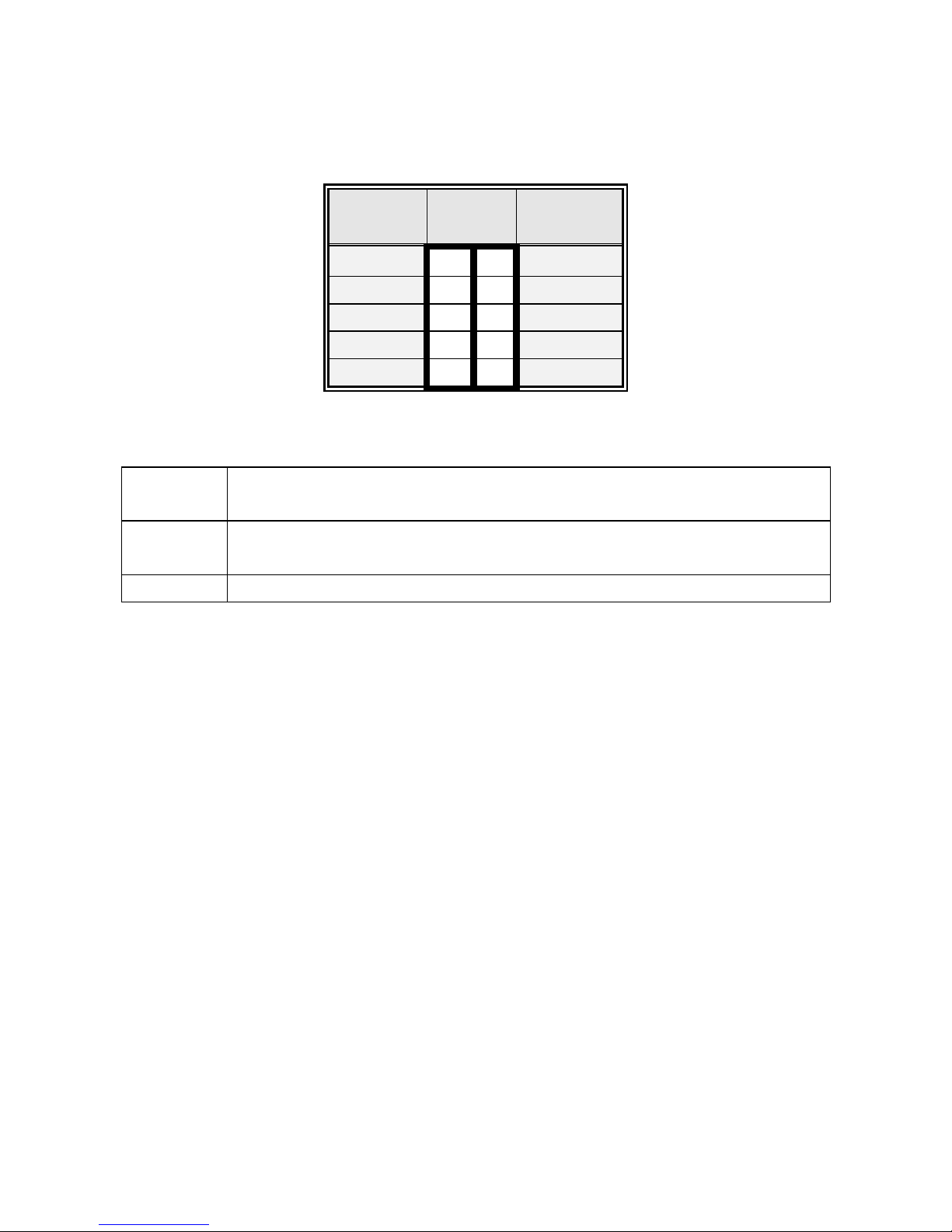
4.5.17 USB Connector (USB1)
Signal
PIN
CH1 CH2
Signal
VCC1 1 2 GND
D1- 3 4 GND
D1+ 5 6 D2+
GND 7 8 D2GND 9 10
VCC2
4.5.18 Signal Description – USB Connector (USB1)
D1+ / D1- Differential bi-directional data signal for USB channel 0. Clock is transmitted along with the
data using NRZI encoding. The signalling bit rate is up to 12 Mbs.
D2+ / D2- Differential bi-directional data signal for USB channel 1. Clock is transmitted along with the
data using NRZI encoding. The signalling bit rate is up to 12 Mbs.
VCC 5 V DC supply for external devices. Maximum load according to USB standard.
Page 28
EES-3610
EES-3610 Quick Reference Guide
28
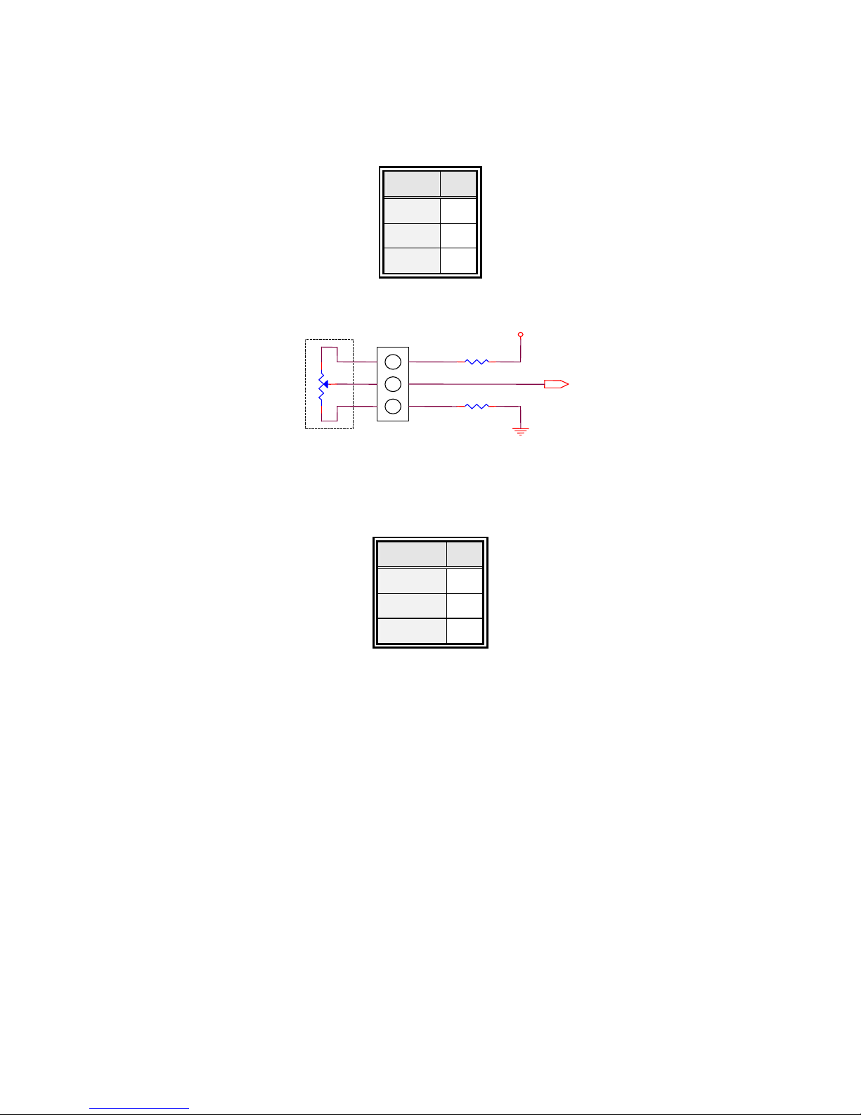
4.5.19 LCD Backlight Brightness Adjustment Connector (VR1)
Signal PIN
GND 1
VR 2
VCC 3
VCC
J3 pin 4
VR1
1 2 3
Variation Resistor (Recommended: 4.7KΩ, >1/16W)
4.5.20 STN LCD Contrast Adjustment Connector (VR2)
Signal PIN
GND 1
VCON 2
VCC 3
Page 29
Quick Reference Guide
EES-3610 Quick Reference Guide
29
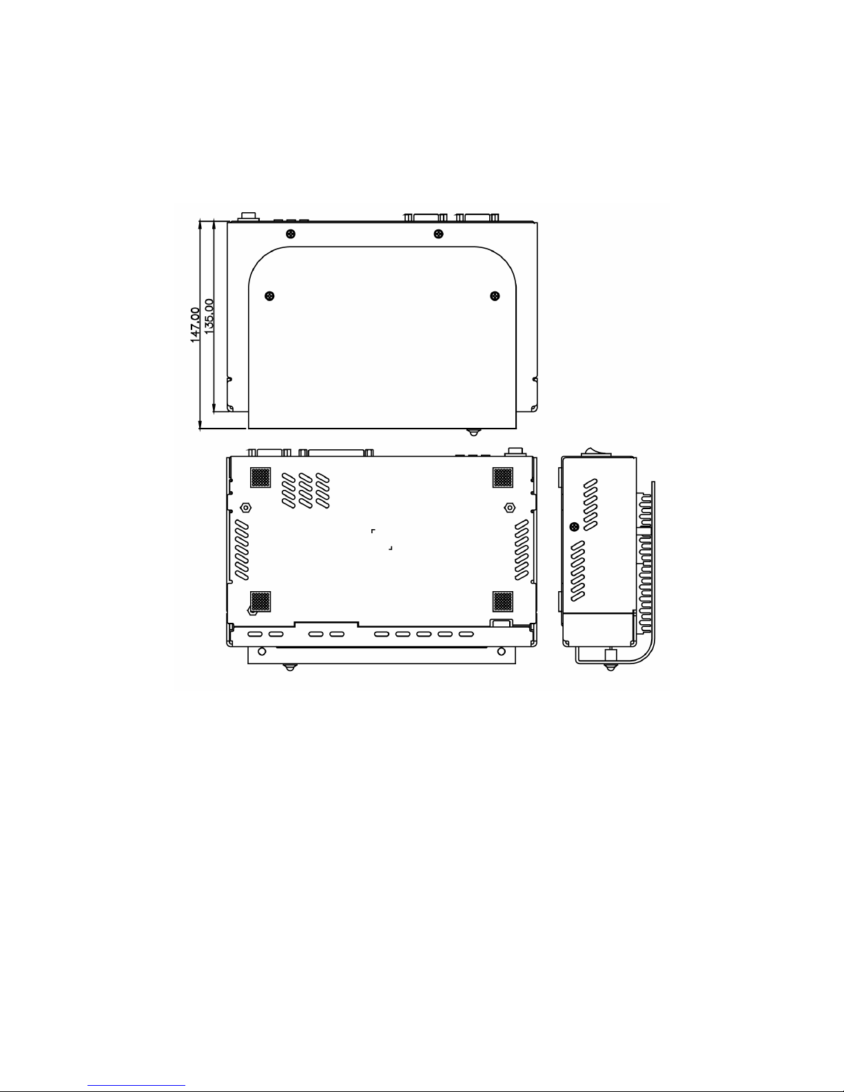
5. Mechanical Drawings
5.1 Dimension Drawing
Page 30
EES-3610
EES-3610 Quick Reference Guide
30
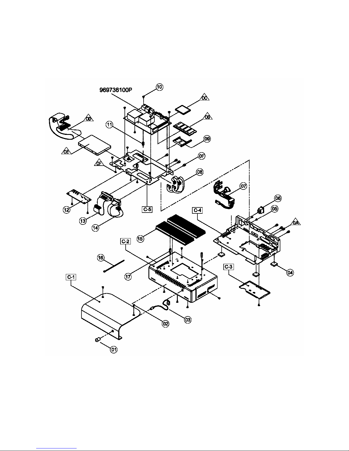
5.2 Explode Drawing
Page 31
Quick Reference Guide
EES-3610 Quick Reference Guide
31
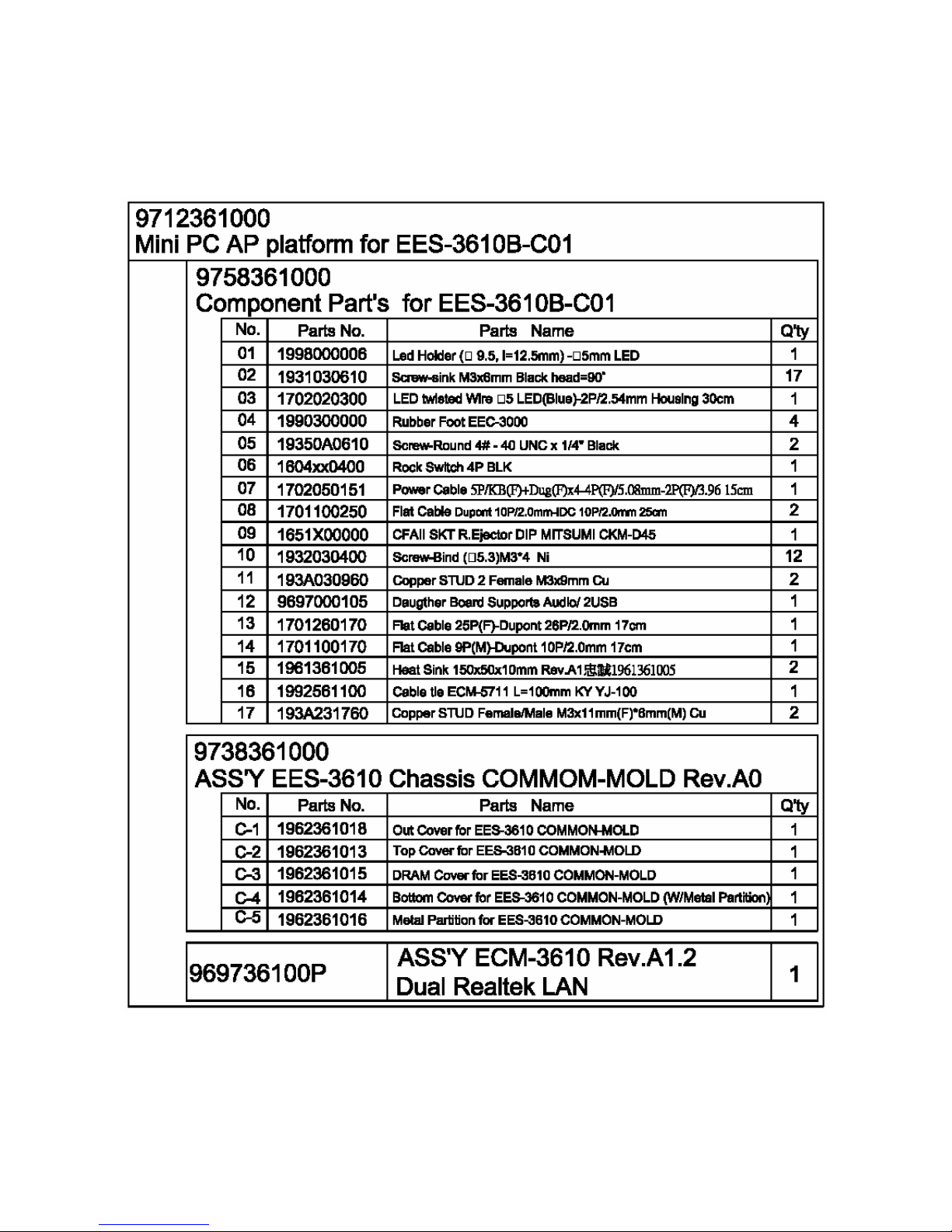
5.3 Chassis Part List
Page 32

EES-3610
EES-3610 Quick Reference Guide
32
 Loading...