

EVA MAJOLICA LINE, PELLET LINE, SLIM LINE Instruction Manual
PELLET STOVES
INSTRUCTION MANUAL
MAJOLICA
LINE
SLIM
LINE
EN
PELLET
LINE
1
IMPORTANT:
READ THE FOLLOWING
INFORMATION
1. The warranty is valid only if the FIRST IGNITION is carried out by an AUTHORISED TECHNICIAN.
2. DO NOT TURN THE PRODUCT UPSIDE DOWN or LAY IT IN A HORIZONTAL POSITION during
transportation and installation.
3. Stove installation must be carried out by qualified staff and pursuant to the regulations in force
in the relevant country.
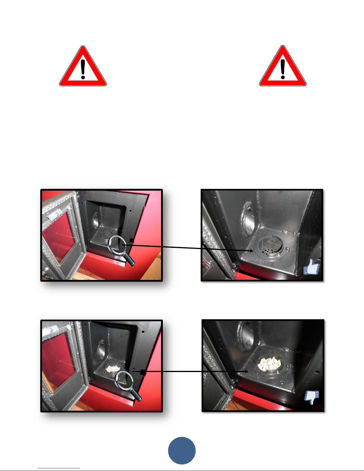
4. EMPTY THE BURN POT before trying to switch the stove back on in case of ignition failure or power
outage. Failure to do so may also result in the breaking of the door glass.
2
3
5. DO NOT POUR PELLETS BY HAND in the burn pot to facilitate stove's ignition.
6. Should any anomaly concerning the flame be detected or, however, in any other case, NEVER
SWITCH OFF the stove by disconnecting it from the mains. Use the relevant button. Disconnecting
the stove from the mains will prevent exhaust fumes from being extracted.
7. Should ignition phase take longer than expected (due to damp or poor quality pellets) generating
excessive smoke in the combustion chamber, open the door to expel it, while remaining in a position
that guarantees your safety.
8. It is highly important to use GOOD QUALITY CERTIFIED PELLETS. The manufacturer declines any
liability for any malfunctioning or damage to mechanical parts due to the use of poor quality pellets.
9. The burn pot and the combustion chamber MUST BE CLEANED DAILY. The manufacturer declines
any liability for any malfunctioning due to a failure to do so.
Eva Stampaggi S.r.l. declines any liability for any damage to persons or
property arising from the failure to comply with the points mentioned
above and from non-compliant product installation.

INDICE
4
01. SAFETY WARNING ................................................................................................................ 8
02. GENERAL SAFETY PRECAUTIONS ........................................................................................... 9
03. VENT PIPE ........................................................................................................................... 11
04. CHIMNEY COWL.................................................................................................................. 13
05. DRAUGHT ........................................................................................................................... 14
06. STOVE EFFICIENCY .............................................................................................................. 15
07. INSTALLATION INSTRUCTIONS ............................................................................................ 16
08. DATA PLATES ...................................................................................................................... 24
09. MICRONOVA ELECTRONICS WITH LED DISPLAY ................................................................... 27
09.1 Proper functioning and control adjustment devices ............................................................................. 27
09.1.1 Panel description ....................................................................................................................... 27
09.2 LED indicators ....................................................................................................................................... 28
09.3 The displays .......................................................................................................................................... 28
09.4 User functions ...................................................................................................................................... 29
09.4.1 Stove switching on ..................................................................................................................... 29
09.4.2 Pellet manual loading ................................................................................................................ 29
09.4.3 Fire on ........................................................................................................................................ 29
09.4.4 Working mode ........................................................................................................................... 29
09.4.5 Changing set heat output .......................................................................................................... 29
09.4.6 Changing set room temperature .............................................................................................. 29
09.4.7 Stove switching off .................................................................................................................... 29
09.4.8 Burn pot cleaning ....................................................................................................................... 30
09.4.9
Prog
rammable thermostat ....................................................................................................... 30
09.5 Alarms .................................................................................................................................................. 31
09.5.1 Fume temperature sensor alarm ............................................................................................... 31
09.5.2 Fume overheating alarm ........................................................................................................... 31
09.5.3 Ignition failure alarm ................................................................................................................. 32
09.5.4 Stove switching-off during working mode alarm....................................................................... 32
09.5.5 Negative pressure alarm ............................................................................................................ 32
09.5.6 General safety thermostat alarm .............................................................................................. 32
09.5.7 No electrical supply alarm ......................................................................................................... 32
09.5.8 Damage exhaust blower alarm .................................................................................................. 32
09.6 Stoves with ducting system .................................................................................................................. 32
09.6.1 Fan no. 2 speed setting .............................................................................................................. 32
10. MICRONOVA ELECTRONICS WITH LCD DISPLAY .................................................................. 33
10.1 Proper functioning and control adjustment devices ............................................................................. 33
10.1.1 Control panel ............................................................................................................................. 33
10.1.2 Panel description ....................................................................................................................... 34
10.2 Menu .................................................................................................................................................... 34
10.2.1 User menu ................................................................................................................................. 34
10.2.2 Menu 01 – fan adjustment ........................................................................................................ 36
10.2.3 Menu 02 – time clock setting .................................................................................................... 37
10.2.4 Menu 03 – chrono setting ......................................................................................................... 37
10.2.5 Menu 04 – select language ........................................................................................................ 39
10.2.6 Menu 05 – stand-by mode......................................................................................................... 39
10.2.7 Menu 06 – buzzer mode ............................................................................................................ 39
10.2.8 Menu 07 – initial load ................................................................................................................ 40
10.2.9 Menu 08 – stove status ............................................................................................................. 40
10.2.10 Menu 09 – kind of fuel ............................................................................................................. 41

INDICE
5
10.3 User functions ..................................................................................................................................... 41
10.3.1
Stove switching on
.................................................................................................................. 41
10.3.2 Start-up phase ........................................................................................................................... 41
10.3.3 Ignition failure ........................................................................................................................... 41
10.3.4 Working mode ........................................................................................................................... 42
10.3.5 Changing set room temperature ............................................................................................... 42
10.3.6 External thermostat/programmable thermostat ...................................................................... 42
10.3.7 Room temperature reaches set value (SET temperature) ......................................................... 42
10.3.8 Burn pot cleaning ....................................................................................................................... 43
10.3.9 Stove switching off .................................................................................................................... 43
10.3.10 Stove switched of .................................................................................................................... 43
10.3.11 Switching on the stove again ................................................................................................... 44
10.4 What happens in case of… .................................................................................................................... 44
10.4.1 Pellet ignition failure ................................................................................................................. 44
10.4.2 Power outage............................................................................................................................. 44
10.5 Alarms .................................................................................................................................................. 45
10.5.1 Fume temperature sensor alarm ............................................................................................... 45
10.5.2 Fume overheating alarm ........................................................................................................... 45
10.5.3 Ignition failure alarm ................................................................................................................ 45
10.5.4 Stove switching-off during working mode alarm ...................................................................... 46
10.5.5 Auger tube safety pressure switch alarm .................................................................................. 46
10.5.6 General thermostat alarm ......................................................................................................... 46
10.5.7 Damaged exhaust blower alarm ................................................................................................ 46
11. N100 MICRONOVA ELECTRONICS WITH 3-BUTTON LED DISPLAY ......................................... 47
11.1 Proper functioning and control adjustment devices ............................................................................. 47
11.1.1 Control panel ............................................................................................................................. 47
11.1.2 LED indicators ............................................................................................................................ 47
11.2 Menu .................................................................................................................................................... 48
11.2.1 User menu ................................................................................................................................. 48
11.2.2 Menu 01 – time clock setting .................................................................................................... 49
11.2.3 Menu 02 – chrono setting ......................................................................................................... 51
11.2.4 Menu 03 – select language ........................................................................................................ 53
11.2.5 Menu 04 – stand-by mode......................................................................................................... 53
11.2.6 Menu 05 – buzzer mode ............................................................................................................ 53
11.2.7 Menu 06 – first load................................................................................................................... 54
11.2.8 Menu 07 – stove status ............................................................................................................. 54
11.2.9 Menu 08 – technician settings ................................................................................................... 54
11.2.10 Menu 09 – exit ......................................................................................................................... 54
11.3 User function ........................................................................................................................................ 55
11.3.1 Stove switching on ..................................................................................................................... 55
11.3.2 Pellet feeding ............................................................................................................................. 55
11.3.3 Fire on ........................................................................................................................................ 56
11.3.4 Working mode ........................................................................................................................... 56
11.3.5 Changing set heat output .......................................................................................................... 56
11.3.6 Changing set room temperature ............................................................................................... 57
11.3.7 Room temperature reaches set value (SET temperature) ......................................................... 57
11.3.8 Stand-by ..................................................................................................................................... 57
11.3.9 Stove switching off .................................................................................................................... 58

INDICE
6
11.4 Alarms .................................................................................................................................................. 59
11.4.1 Power outage alarm .................................................................................................................. 59
11.4.2 Fume temperature sensor alarm ............................................................................................... 59
11.4.3 Fume overheating alarm ........................................................................................................... 59
11.4.4 Faulty fume encoder alarm ....................................................................................................... 60
11.4.5 Ignition failure alarm ................................................................................................................. 60
11.4.6 No pellet alarm .......................................................................................................................... 60
11.4.7 Thermal safety overheating alarm............................................................................................. 60
11.4.8 No negative pressure alarm ....................................................................................................... 60
11.5 Connections .......................................................................................................................................... 61
12. N100 MICRONOVA ELECTRONICS WITH 6-BUTTON LED DISPLAY ......................................... 62
12.1 Proper functioning and control adjustment devices ............................................................................. 62
12.1.1 Control panel ............................................................................................................................. 62
12.1.2 LED indicators ............................................................................................................................ 62
12.2 Menu .................................................................................................................................................... 63
12.2.1 User menu ................................................................................................................................. 63
12.2.2 Menu 01 – time clock setting .................................................................................................... 64
12.2.3 Menu 02 – chrono setting ......................................................................................................... 64
12.2.4 Menu 03 – select language ........................................................................................................ 66
12.2.5 Menu 04 – stand-by mode......................................................................................................... 66
12.2.6 Menu 05 – first load................................................................................................................... 66
12.2.7 Menu 06 – stove status ............................................................................................................. 66
12.2.8 Menu 07 – technician settings ................................................................................................... 66
12. User function ......................................................................................................................................... 66
12.3.1 Stove switching on ..................................................................................................................... 66
12.3.2 Pellet feeding ............................................................................................................................. 67
12.3.3 Fire on ........................................................................................................................................ 67
12.3.4 Working mode ........................................................................................................................... 67
12.3.5 Changing set heat output .......................................................................................................... 67
12.3.6 Changing set room temperature ............................................................................................... 67
12.3.7 Room temperature reaches set value (SET temperature) ......................................................... 67
12.3.8 Stand-by ..................................................................................................................................... 67
12.3.9 Stove switching off .................................................................................................................... 67
12.4 Alarms .................................................................................................................................................. 68
12.4.1 Power outage alarm .................................................................................................................. 68
12.4.2 Fume temperature sensor alarm ............................................................................................... 68
12.4.3 Fume overheating alarm ........................................................................................................... 68
12.4.4 Faulty fume encoder alarm ....................................................................................................... 68
12.4.5 Ignition failure alarm ................................................................................................................. 68
12.4.6 No pellet alarm .......................................................................................................................... 68
12.4.7 Thermal safety overheating alarm............................................................................................. 68
12.4.8 No negative pressure alarm ....................................................................................................... 68
12.5 Connections .......................................................................................................................................... 69
13 MICRONOVA ELECTRONICS WITH REMOTE CONTROL ........................................................... 70
13.1 Proper functioning and control adjustment devices ............................................................................. 70
13.1.1 Control panel ............................................................................................................................. 70
13.1.2 Panel description ....................................................................................................................... 70
13.1.3 Emergency panel ....................................................................................................................... 71

INDICE
7
13.2 Menu .................................................................................................................................................... 71
13.2.1 User menu ................................................................................................................................. 71
13.2.2 Menu 01 – fan adjustment ........................................................................................................ 73
13.2.3 Menu 02 – time clock setting .................................................................................................... 73
13.2.4 Menu 03 – chrono setting ......................................................................................................... 74
13.2.5 Menu 04 – select language ........................................................................................................ 76
13.2.6 Menu 05 – select sensor ............................................................................................................ 76
13.2.7 Menu 06 – stand-by mode......................................................................................................... 76
13.2.8 Menu 07 – buzzer mode ............................................................................................................ 76
13.2.9 Menu 08 – initial load ................................................................................................................ 76
13.2.10 Menu 09 – stove status ........................................................................................................... 76
13.3 User functions ...................................................................................................................................... 77
13.3.1 Stove switching on ..................................................................................................................... 77
13.3.2 Start-up phase ........................................................................................................................... 77
13.3.3 Ignition failure ........................................................................................................................... 77
13.3.4 Working mode ........................................................................................................................... 77
13.3.5 Changing set room temperature ............................................................................................... 78
13.3.6 External thermostat/programmable thermostat ...................................................................... 78
13.3.7 Room temperature reaches set value (SET temperature) ......................................................... 78
13.3.8 Burn pot cleaning ....................................................................................................................... 78
13.3.9 Stove switching off .................................................................................................................... 79
13.3.10 Stove switched of .................................................................................................................... 79
13.3.11 Switching on the stove again ................................................................................................... 79
13.4 What happens in case of… .................................................................................................................... 80
13.4.1 Pellet ignition failure ................................................................................................................. 80
13.4.2 Power outage............................................................................................................................. 80
13.5 Alarms .................................................................................................................................................. 81
13.5.1 Fume temperature sensor alarm ............................................................................................... 81
13.5.2 Fume overheating alarm ........................................................................................................... 81
13.5.3 Ignition failure alarm ................................................................................................................. 81
13.5.4 Stove switching-off during working mode alarm....................................................................... 81
13.5.5 Auger tube safety pressure switch alarm .................................................................................. 81
13.5.6 General thermostat alarm ......................................................................................................... 81
13.5.7 Damaged ehaust blower alarm ................................................................................................. 81
13.5.8 Trying to connect ....................................................................................................................... 81
14. CLEANING AND MAINTENACE ............................................................................................. 82
14.1 Forewords ............................................................................................................................................ 82
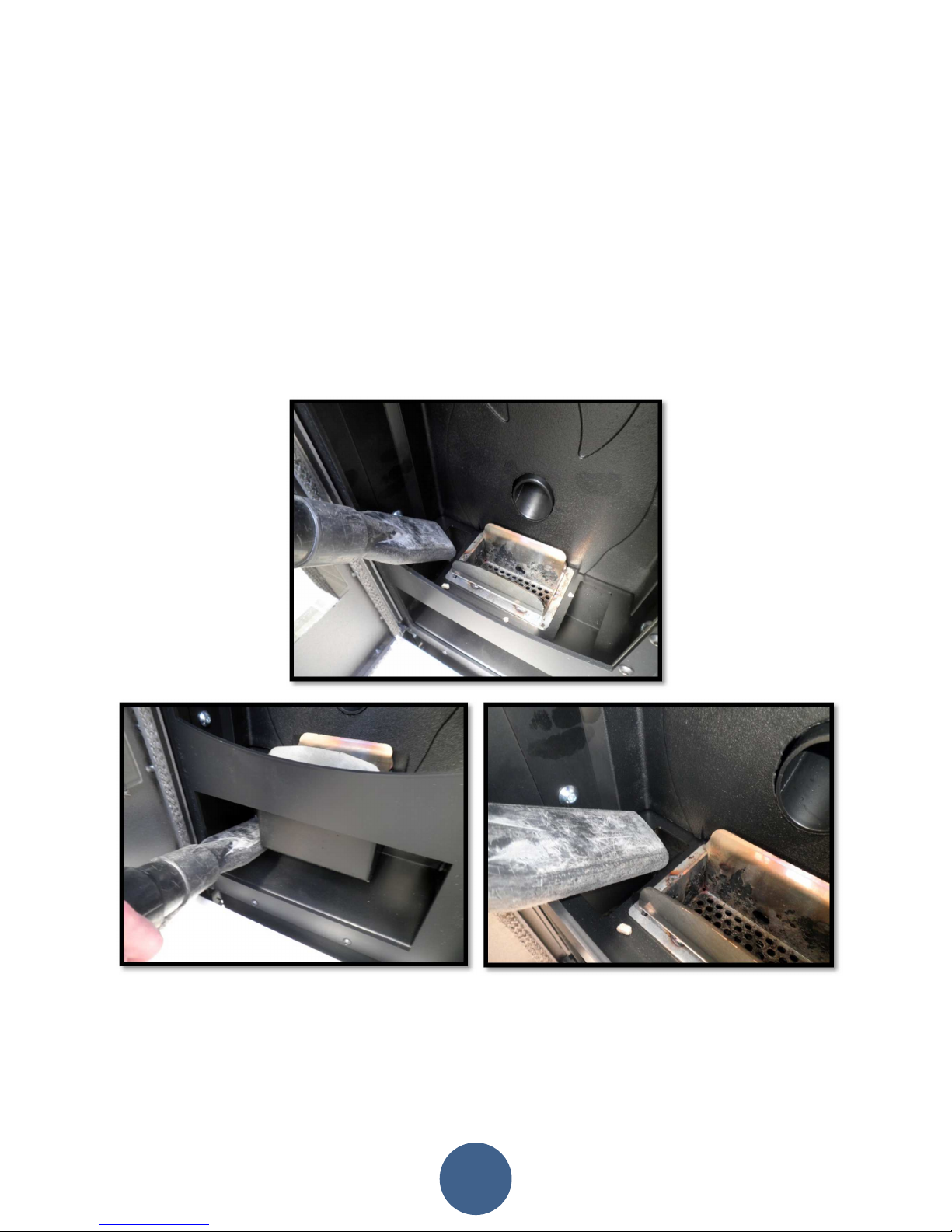
14.2 Daily cleaning ....................................................................................................................................... 82
14.3 Manufacturer’s liability ........................................................................................................................ 82
15. TROUBLESHOOTING ........................................................................................................... 83
16. ANNUAL MAINTENACE SCHEDULE ...................................................................................... 85
17. INSTALLATION AND TESTING CERTIFICATE .......................................................................... 86
18. WARRANTY CERTIFICATE .................................................................................................... 88
01. SAFETY WARNING
8
Stoves are manufactured according the EN13240 (wood stoves), EN 14785 (Pellet stoves), EN 12815 (cook stoves and central heating
cookers), using first grade and no-polluting raw materials and components. In order to use at best your stove, it is raccomanded to
follow the instructions of the manual.
Carefully read this instructions manual before using or any maintenance intervent.
Eva Stampaggi is aimed to supply the most of information as possible, in order to grant a more sure utilization and to avoid injures
and damages to the components of the stove itself.
Each stove undergoes an internal test before the shipment , therefore some burning residual can be found inside the burning
chamber.
KEEP SAFE THE UNSTRUCTIONS MANUAL FOR FURTHER
INQUIRIES FOR ANY NEEDS APPLY TO
AUTHORIZED PERSONNEL
• Installation and connection must be carried out by qualified staff in compliance with local regulations, national and
European standards (UNI 10683) and with the installation instructions contained herein. The electrical system of the room
where the stove is to be installed must comply with current regulations.
• The combustion of waste, especially of plastic materials, damages the stove and the vent pipe. Moreover, it is forbidden by
the law against the emission of harmful substances.
• Do not use alcohol, petrol or other highly inflammable liquids to light the fire or poke it during operation.
• Do not put in the stove a quantity of wood bigger then the one stated on the instructions manual.
• Do not modify the product.
• It is forbidden to use the stove if the door is open or the door glass is broken.
• Do not use the stove as a clotheshorse, a support surface or stair etc.
• Do not install the stove in the bed room or in the bath room.

9
02. GENERAL SAFETY PRECAUTIONS
• Use the stove only as described in this manual. Any other use not recommended by the manufacturer may cause fires or
accidents to people.
• Make sure that the electrical power available corresponds to the value indicated in the data plate (220V~/50Hz).
• This appliance is not a toy. Make sure children are not left unattended and do not use the appliance as a toy.
• This device is not intended for use by persons (including children) with reduced physical or mental capacity, or without
specific experience and knowledge, unless supervised or duly instructed on the use of the appliance by a person
responsible for their safety.
• Disconnect the appliance from the mains when not in use or during cleaning operations.
• To do so, turn the switch to the O position and disconnect the plug from the socket. Pull the plug, not the cable.
• Never block the combustion air inlets and fume outlets.
• Since the stove is fitted with electrical components, do no touch it with wet hands.
• Do not use the appliance in case of damaged cables or plugs. This appliance can be classified as Y type: power supply
cable can be replaced only by qualified technicians. Should the power supply cable be damaged, it can be replaced only
by the manufacturer or by its technical assistance service or by a similarly qualified person.
• Do not place any object on the cable and do not bend it.
• Avoid using extension cables as their temperature may increase excessively posing fire hazards. Never use one single
extension cable to power several appliances.
•
During normal functioning some parts of the stove may become extremely hot, such as the door, the glass or the
handle. Be careful, especially with children. Do not touch any hot parts if not wearing adequate protective devices.
•
CAUTION! DO NOT TOUCH the FIRE DOOR, the GLASS, the HANDLE or the FUME OUTLET DURING FUNCTIONING if not
wearing adequate protective devices since they become extremely hot.
• Keep inflammable materials, such as furniture, cushions, pillows, blankets, paper, clothing, curtains, etc., at least 1 m
away from the stove front and 30 cm from the stove sides and back.
• Do not immerse the cable, plug or any other appliance component in water or other liquids.
• Do not use the stove in dusty environments or wherever inflammable vapours are generated (e.g. a workshop or a garage).
• The stove being covered by or in direct contact with inflammable materials, including curtains, blankets, etc, during normal
operation may result in a fire hazard. KEEP THE APPLIANCE AWAY FROM THE MATERIALS MENTIONED ABOVE.
• The stove is fitted with components that generate arcs and sparks. Do not install the stove in areas posing a significant
fire or explosion hazard due to a high chemical substance concentration or to a high humidity level.
• Do not use the appliance close to bathtubs, showers, basins, sinks or swimming pools.
• Do not install the appliance underneath an air vent. Do not install the stove outdoors.
• Do not repair, disassemble or modify the appliance. The appliance is not fitted with components that can be repaired by
users.
• Turn off the stove, disconnect it from the mains and wait until it has cooled down completely before performing any
maintenance operations.
•
WARNING: DISCONNECT THE STOVE FROM THE MAINS BEFORE PERFORMING MAINTENANCE OPERATIONS.
•
CAUTION! This stove works exclusively with pellets
and walnut shells, if the stove is designed to
. DO NOT USE ANY
OTHER FUEL since it would damage the appliance and cause its malfunctioning.
• Store pellets in a cool and dry place. Storing pellets in a damp or too cold place may reduce the stove potential heat output.
Be careful when storing and handling pellet bags to prevent pellet crushing and sawdust production.
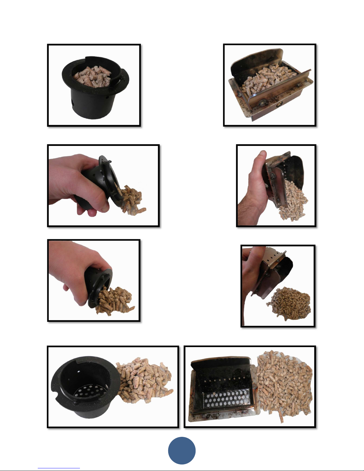
• Clean the burn pot on a regular basis upon every ignition or pellet refuelling.
• Open the firebox only upon refuelling or removal of residues to prevent fumes from escaping.
• Do not switch the stove on and off intermittently to avoid damaging its electrical and electronic components.
• Do not use the appliance as waste incinerator or for any other purpose other than the intended one.
• Do not use liquid fuels.
• Do not modify the appliance without prior authorisation.
• Use only original spare parts recommended by the manufacturer.
• The fuel consists of small cylinders with 6-7mm diameter and a maximum length of 30mm. Their maximum moisture content
is equal to 8%. This stove is designed to burn pellets made of compacted sawdust obtained from different types of wood, in
compliance with environment protection legislation.
• The use of different types of pellets may result in a slight, sometimes even undetectable, change in the stove efficiency.
This change can be counterbalanced by increasing or decreasing the stove heat output by only one step.
• Make sure that the stove is transported in compliance with safety regulations. Avoid any improper transfers or knocks that
may damage the ceramics or the structure.

02. GENERAL SAFETY PRECAUTIONS
10
• The metal structure is coated using high temperature paints. When switching on the stove for the first times,
unpleasant odours may be emitted as the paint starts to harden on the metal parts. The fumes emitted are not harmful.
Ventilate the room to evacuate them. After the first heating cycles, the paint will reach its maximum adhesion and all
its chemical and physical features.
• The hopper can contain up to 15 kg of pellets. Open the lid and pour the pellets to load it, also during normal operation,
making sure that no pellets fall out of it. Always refuel the hopper before leaving the operating stove unattended for
long periods of time.
• Whenever the hopper and the Auger tube get completely empty, the appliance will be automatically switched off. It may take
two separate ignitions to resume operation at ideal working conditions since the Auger tube is very long.
• CAUTION! If the stove is not properly installed, power outages may result in fume spillages.
• Under specific circumstances, an uninterrupted power supply unit must be installed.
•
CAUTION!
Being a heating appliance, some parts of the stove can become extremely hot. We therefore recommend
paying special attention during operation:
WHEN THE STOVE IS WORKING:
o do no t open the door;
o do not touch the door glass since it becomes extremely hot;
o keep children away from it;
o do not touch the fume outlet;
o do not pour any liquid inside the firebox;
o do not perform any maintenance operations if the stove is not cold;
o only qualified technicians are allowed to perform any operation;
o follow all the instructions contained herein.
Anti-explosion
Some products are fitted with a safety device to prevent explosion. Before switching on the product or, in any case, after any
cleaning operation, make sure that the device is correctly positioned in its seat. The device is located on the firebox door upper
edge.
03. VENT PIPE
11
The vent pipe is one of the key features for guaranteeing the proper functioning of the stove. Thanks to the quality of the materials,
the strength, the durability, the easy cleaning and maintenance, the best vent pipes are made of steel, either stainless steel or
aluminized.
• The stove is fitted with a Φ 80mm rear round fume outlet and a joint connection to be connected to the vent pipe.
• Use telescopic joint connections to facilitate connection to the steel rigid vent pipe and counterbalance the thermal
expansion of both the firebox and the vent pipe.
• Seal the vent pipe joint connection with high temperature silicone sealant (1,000°C). Should the existing flue opening not
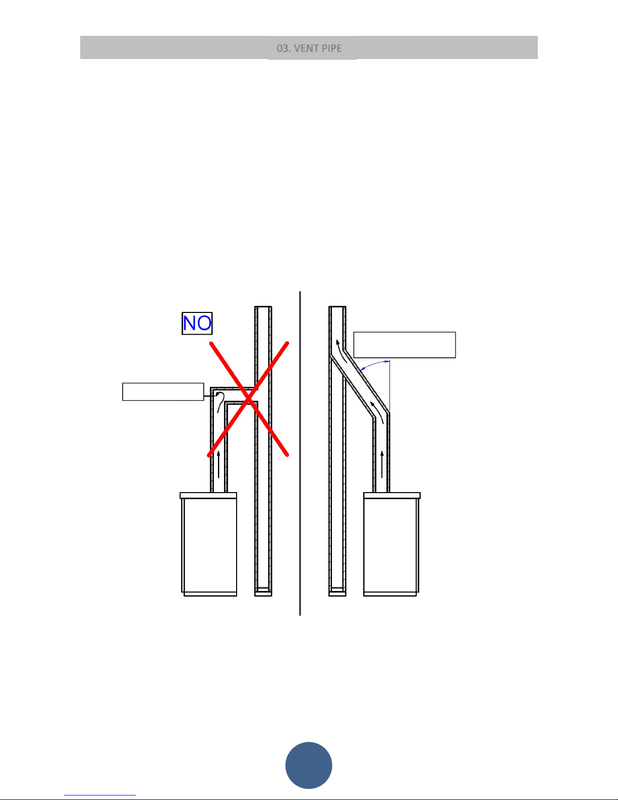
be perfectly perpendicular to the firebox fume outlet, use an elbow to connect them. Inclination must never exceed 45°,
with respect to the vertical axis. No constrictions.
• Use 10cm-thick insulating thimbles if pipe vent passes through floors.
• The vent pipe must be insulated along its entire length. Thanks to the vent pipe insulation fume temperature will remain high
optimising draught, preventing condensation and reducing build-up of barely ignited particles along the vent pipe walls. Use
proper insulating materials (glass wool, ceramic fibre, Class A1 non-combustible materials).
• Install a vent pipe with a minimum vertical run of 2 mt to guarantee proper draught.
• The vent pipe must be weather-proof and as linear as possible.
• Flexible and length-adjustable metal pipes may not be used.
CONSTRICTION
INCLINATION
LOWER THAN 45°

03. CANNA FUMARIA
12
EXISTING VENT PIPE (TRADITIONAL)
EXTERNAL VENT PIPE
04. CHIMNEY COWL
13
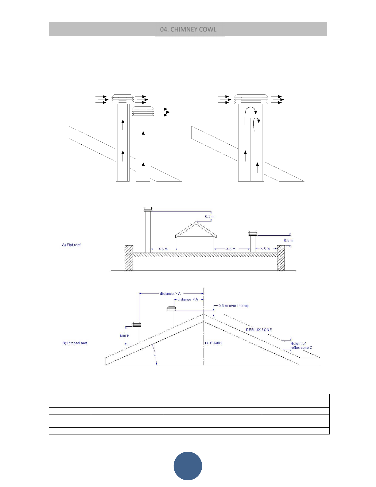
A properly installed chimney cowl ensures optimum stove functioning. The anti-downdraught chimney cowl consists of a number of
components whose outlet section sum always doubles the vent pipe section. Make sure the chimney cowl is at least 150 cm above
the roof top so that it is fully exposed to the wind.
Roof pitch α [°] Horizontal width of reflux zone
measured from top A axis [m]
Minimum height from roof for ischarging
exhaust fumes H min=Z+0.50m
Height of reflux zone Z [m]
15 1,85 1,00 0,50
30 1,50 1,30 0,80
45 1,30 2,00 1,50
60 1,20 2,60 2,10
YES NO

05. DRAUGHT
14
Fumes heat up during combustion, increasing their volume. Their density is therefore lower than the one of the surrounding colder
air.
This difference between the inside and outside temperatures of the chimney results in a negative pressure which increases
proportionally to the vent pipe length and the temperature.
The draught must be stronger than the fume circulation resistance so that all exhaust fumes generated during combustion inside the
stove are drawn upwards through the outlet and the vent pipe. Many weather conditions affect the vent pipe functioning, such as rain,
fog, snow, altitude, and wind being the most important since it can create both negative pressure and dynamic loading.
The wind action varies depending on whether it is ascending, descending or horizontal.
• Ascending wind always results in an increased negative pressure and draught.
• Horizontal wind results in an increased negative pressure as long as the chimney cowl was properly installed.
• Descending wind always diminishes the negative pressure, sometimes inverting it.
Excess draught causes an increase in the combustion temperature and consequently a loss in stove efficiency.
A part of the combustion fumes are drawn up through the vent pipe together with small pellet particles before combustion reducing
stove efficiency, increasing fuel consumption and resulting in the emission of polluting fumes.
At the same time the high fuel temperature, due to an excess amount of oxygen, wears down the combustion chamber
sooner than expected.
On the other hand, poor draught slows down combustion resulting in a decrease in the stove temperature, fume spillage inside the
room, a loss of stove efficiency and dangerous build-up in the vent pipe.
06. STOVE EFFIENCY
15
Highly efficient stoves may pose difficulties for fume extraction.
In order for a vent pipe to work properly its internal temperature must increase as a consequence of the fumes generated during
combustion.
The stove efficiency instead depends on its capacity to deliver most of the generated heat to the surrounding environment. As a
consequence the more efficient the stove, the colder the combustion exhaust fumes, resulting in a reduced draught.
A traditional chimney flue, with a rough design and insulation, is more efficient if used with a traditional open fireplace or a poor
quality stove where most of the heat is lost with the fumes.
Therefore, purchasing a quality stove often entails modifying the existing chimney flue to obtain a better insulation, even when it
already works properly with old appliances.
Poor draught results in the stove not operating when hot or in smoke spillage.
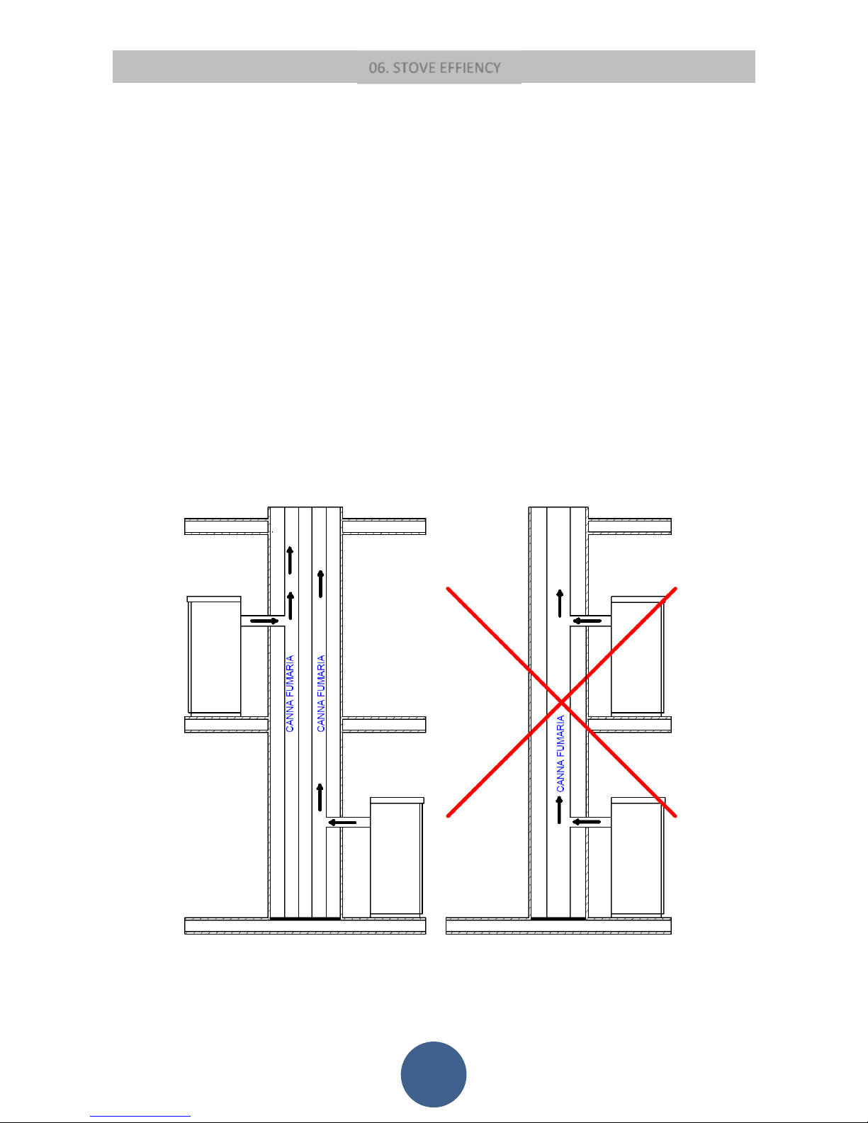
• Connecting the stove pipe to an existing chimney flue that has already been used with an old appliance is a common mistake.
In this way two solid-fuel appliances share the same chimney flue, which is wrong and dangerous.
• If the two appliances are used simultaneously, the fume load might exceed the existing chimney flue capacity resulting in
downdraught. If only one appliance is used, the fume heat will facilitate draught but the cold air coming from the other
appliance not in use will cool down exhaust fume temperature again blocking the draught.
• Besides the problems described so far, if the two appliances are placed on different levels the communicating vessel
principle might be interfered with, causing combustion fumes to be drawn in an irregular and unforeseeable way.
07. INSTALLATION INSTRUCTIONS
16
Follow the instructions below before installing your stove.
Select the position where the stove is to be installed and:
• Arrange the connection to the vent pipe for fume extraction
• Arrange the external air intake (combustion air)
• Arrange the connection to the earthed mains
• The electical system of the room where the stove is to be installed must be earthed, otherwise the control board may not
work properly.
• Place the stove on the floor in a convenient position for the connection to the vent pipe and close to the combustion air
intake.
• The appliance must be installed on a floor with an adequate loading-bearing capacity.
• Should the existing floor not comply with the requirement above, proper measures must be taken (for instance, the
installation of a load distribution plate).
• All the structures which can catch fire if exposed to excessive heat must be protected. Floors made from wood or
inflammable materials must be protected using non-combustible materials (e.g. 4mm-thick sheet metal or ceramic glass).
• The appliance installation must ensure easy access for cleaning the stove, exhaust pipes and vent pipe.
• This appliance is not suitable to be installed on a shared vent pipe.
• During normal operation, the stove draws air from the room where it is installed. Therefore, an external air intake must
be positioned at the same height of the pipe located on the stove back. Exhaust fume pipes must be suitable for pellet
stoves and therefore made from coated steel or stainless steel, with a diameter of 8cm and fitted with adequate gaskets.
• The combustion air intake (
Φ
80mm) must be connected directly to the outside or to adjacent rooms provided they are fitted
with external air supply vents (Φ 80mm) and are not used as bedrooms or bathrooms or, whenever a fire hazard exists, as
storage rooms, garages, combustible material warehouses, etc. The air vents must be placed in such a way that they cannot be
clogged either from the outside or inside and must be protected using a grille, a metal mesh or other suitable means provided
they do not reduce the minimum section.
• If the stove is to be installed in rooms where it is surrounded by combustible materials (e.g. furniture, wood cladding, etc.),
the following minimum clearances must be complied with: “See stove data plate”.
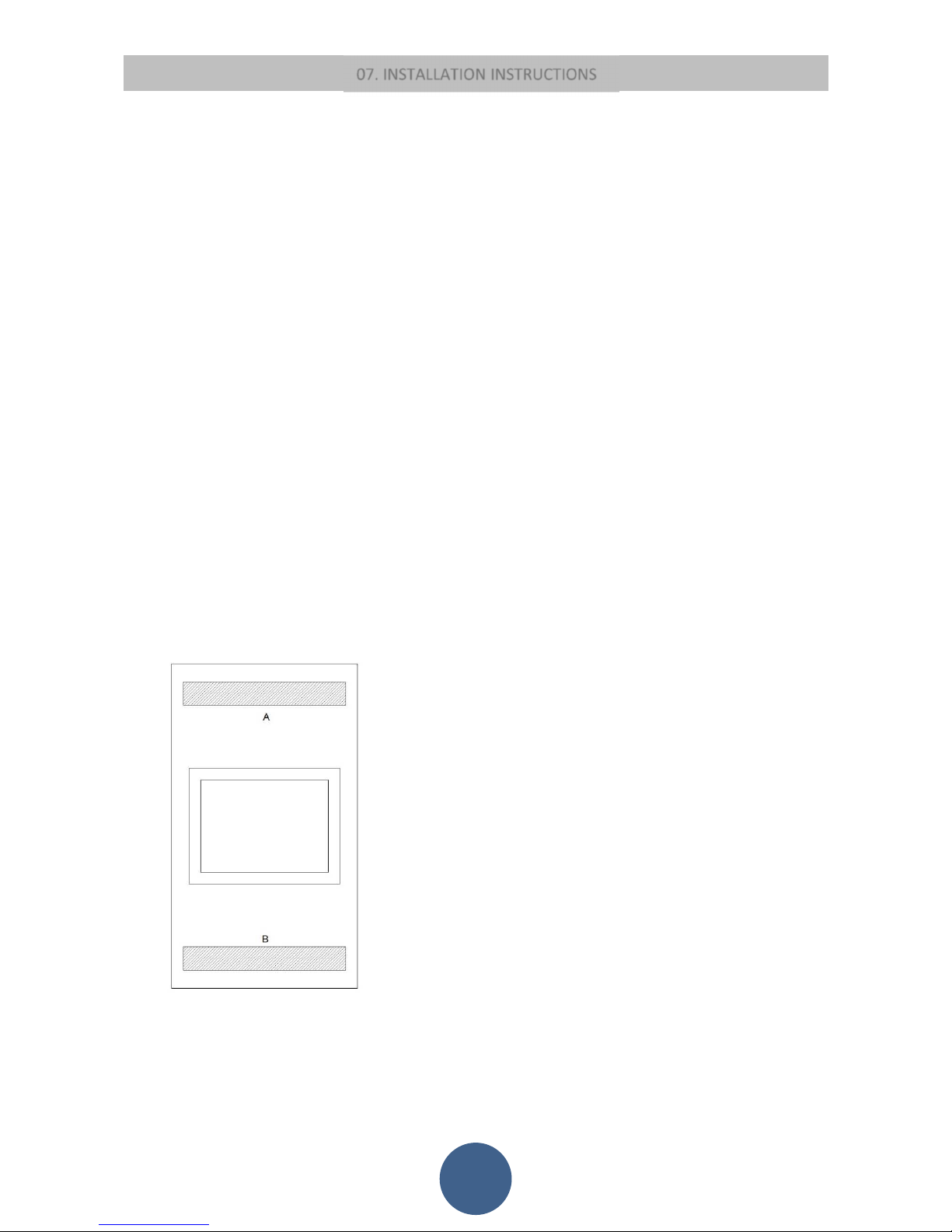
• During installation, the installer must also take into consideration the convective air sections: the structure housing the
appliance must be fitted with ventilation slots.
A = 740 cm²
B = 366 cm²

07. INSTALLATION INSTRUCTIONS
17
• Besides complying with the minimum clearances set above, we also recommend installing heat-resistant fireproof
insulating panels (rock wool, cellular concrete, etc.).
We recommend using the following model:
Promasil 1000
Classification temperature: 1000 °C
Bulk density: 245 kg/m3
Shrinkage at reference temperature, 12 h: 1000°C / 1.3%
Cold crushing strength: 1.4 MPa
Bending strength: 0.5 MPa
Reversible thermal expansion: 5.4x10
-6
m/mK
Specific heat capacity: 1.03 Kj/kg K
Thermal conductivity λ:
200 °C 0.07 W/mK
400 °C 0.10 W/mK
600 °C 0.14 W/mK
800 °C 0.17 W/mK
Thickness: 40 mm
• When working the stove may create a negative pressure inside the room where it is installed. Therefore, it is not possible to
have more than one open flame appliance installed in the same room (the type “C” boilers (room sealed) are the only exception
admitted).
• Make sure that the stove can draw the necessary quantity of combustion air from an open space (i.e. a space without
exhaust blowers or providing adequate ventilation) or directly from outside.
• Do not install the stove in bedrooms or bathrooms.
INSTALLAZION CORNER STOVE
Pursuant to current regulations on installation, the corner stove must be placed in a well-ventilated place to guarantee efficient
combustion and proper functioning. The room must have a volume equal to or higher than 20 m3. An air vent is required to guarantee
efficient combustion (40 m3/h air). It can be connected directly to the outside or to adjacent rooms provided they are fitted with
external air supply vent (80mm) and are not used as a bedroom or bathroom or, whenever a fire hazard exists, as storage room,
garage, combustible material warehouse, etc. . The air vents must be placed in such a way that they cannot be clogged either from
the outside or inside and must be protected using a grille, a metal mesh or other suitable means provided they do not reduce the
minimum cross-section.
When working the corner stove may create a negative pressure inside the room where it is fitted. Therefore, it is not possible to have
more than one open flame appliance installed in the same room (the type “C” boilers (room sealed) are the only exception unless
provided with their own air vent).
The corner stove must be installed far from curtains, armchairs, furniture or other inflammable materials.
The corner stove must not be installed in case of explosive atmospheres or in rooms that may become potentially explosive due to
the presence of appliances, materials or powders causing gas leaks or catching fire easily from sparks. When installing a corner stove
make sure to guarantee adequate clearance from all finishes or beams made from combustible materials, keeping them far from its
irradiation area. Moreover, make sure to prevent heat build-up in the recess, which will result in the insert malfunctioning, by
guaranteeing the required air space, i.e. by respecting minimum clearances and making ventilation slots with a total surface area of
X cm2 cm as shown in the picture below.
07. INSTALLATION INSTRUCTIONS
18
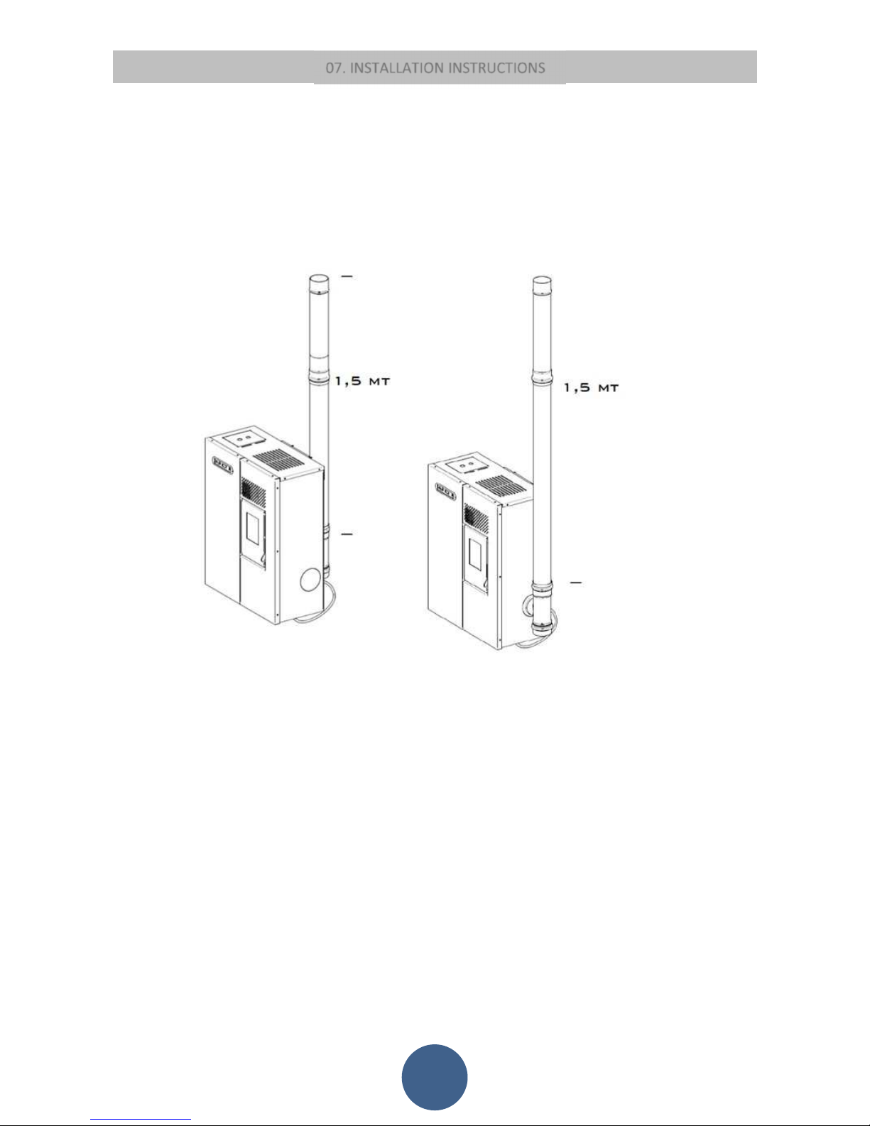
ATTENTION:
4.5 kW stoves must be fitted with a 1.5 m-long pipe (Φ 80 mm) certified to EN 1856-2 standard.
7,5 kW Slim stoves must be fitted with a 1 m-long pipe (Φ 80 mm) certified to EN 1856-2 standard.
9 kW stoves must be fitted with a 1 m-long pipe (Φ 80 mm) certified to EN 1856-2 standard.
11 kW Slim stoves must be fitted with a 1 m-long pipe (Φ 80 mm) certified to EN 1856-2 standard.
07. INSTALLATION INSTRUCTIONS
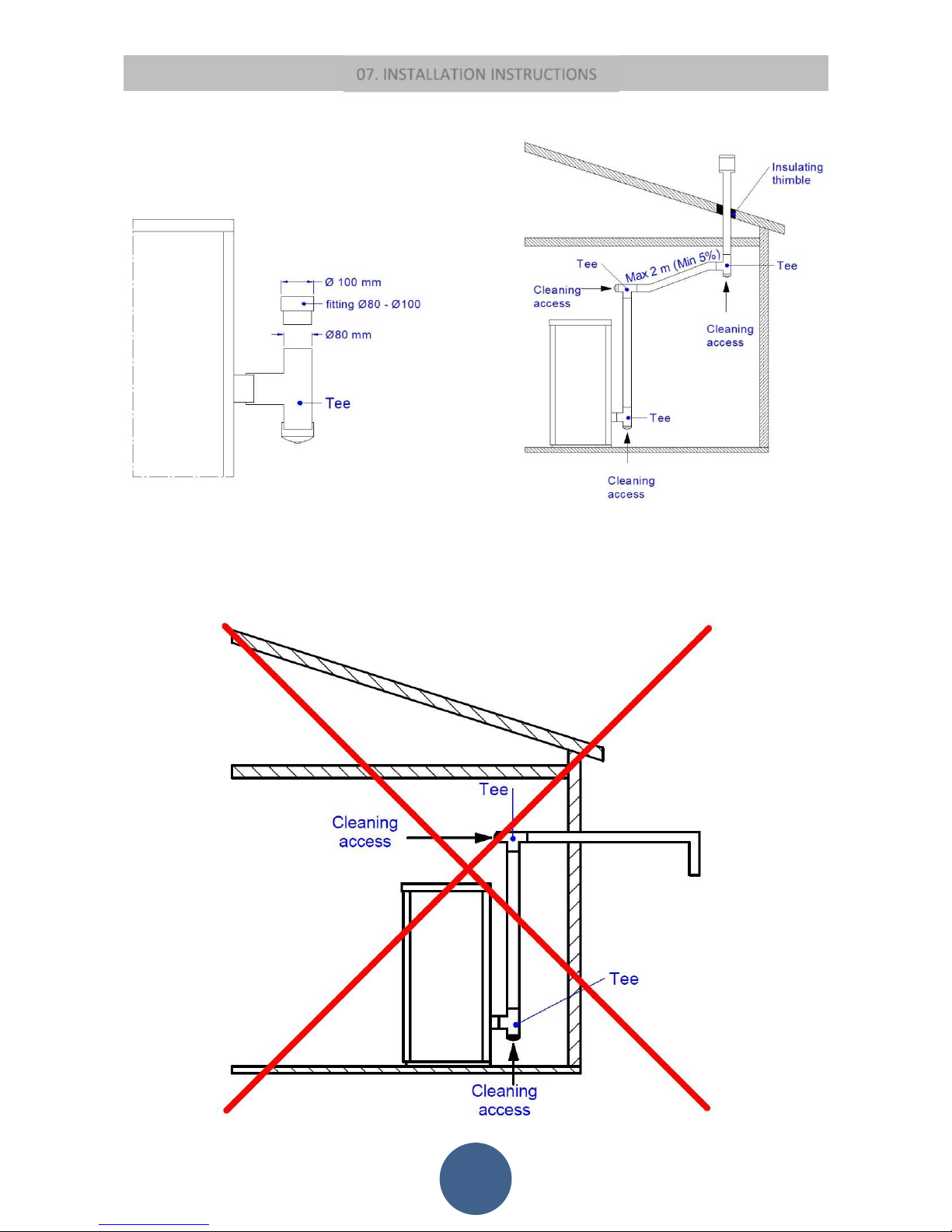
19
INSTALLATION EXAMPLE:
EXAMPLE OF INCORRECT INSTALLATION:
Exhaust pipes must never be fitted pointing downwards or horizontally so that fumes are discharged directly through the external
wall.
07. INSTALLATION INSTRUCTIONS
20
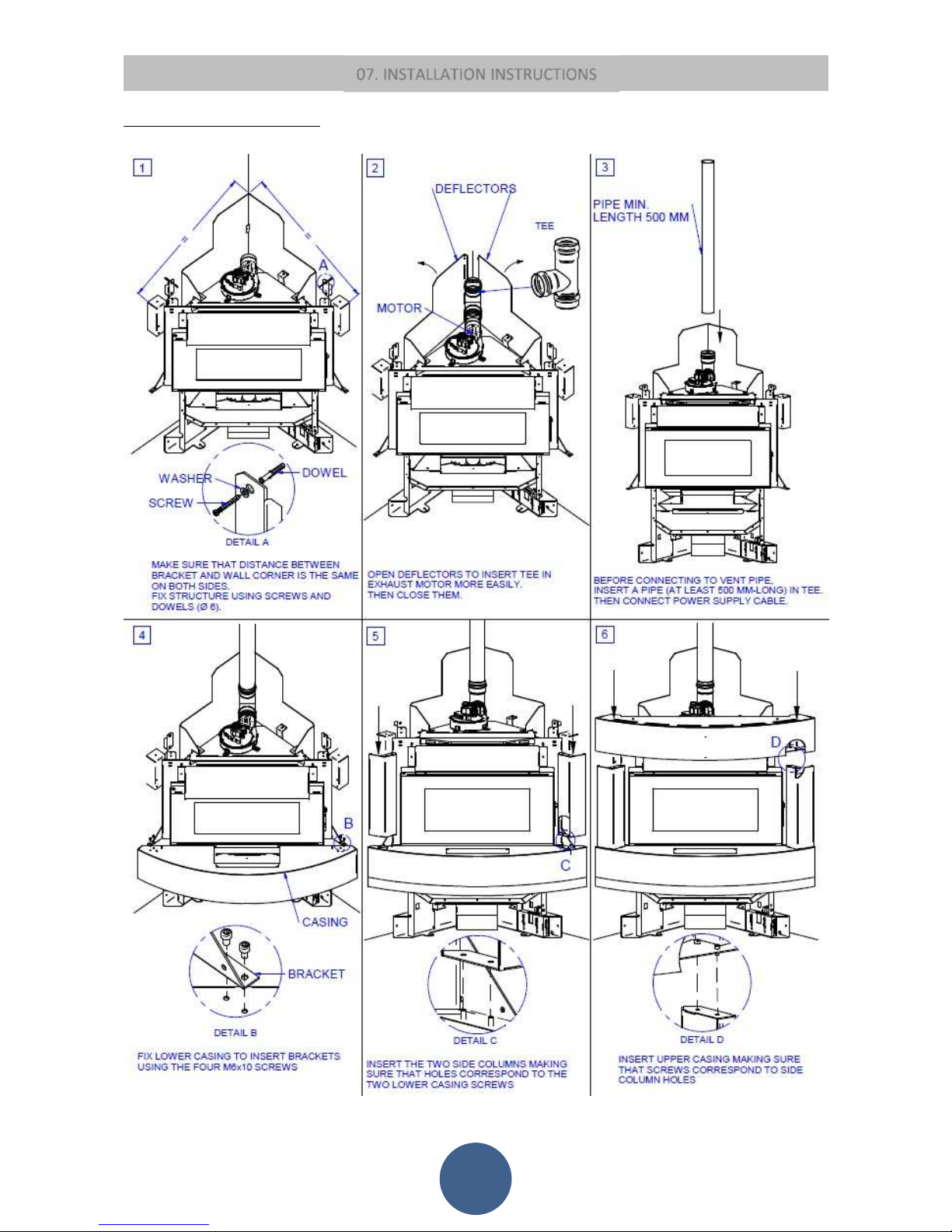
12kW SHEET METAL CORNER STOVE
After making sure that the insert fits into the recess and there are a socket and a vent pipe
21
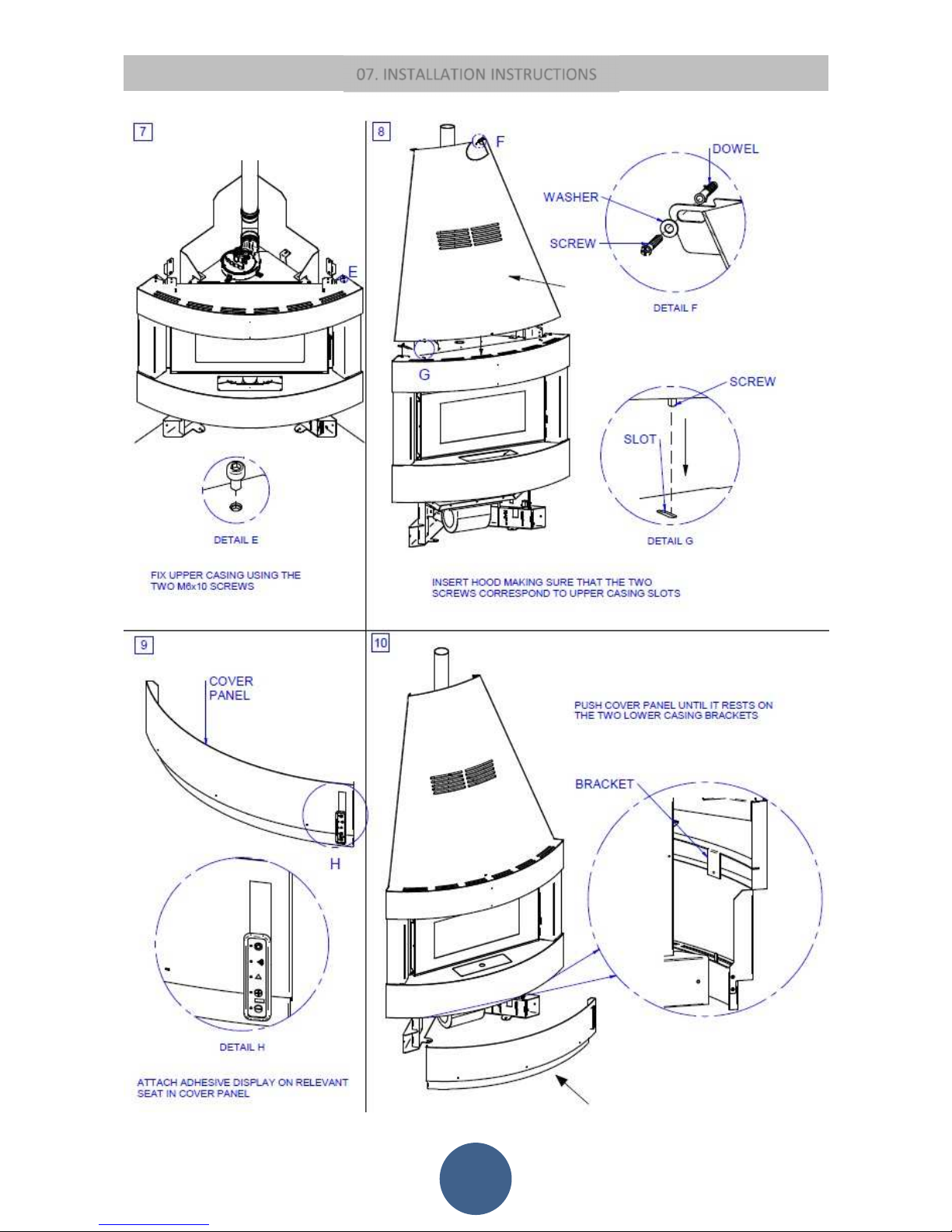
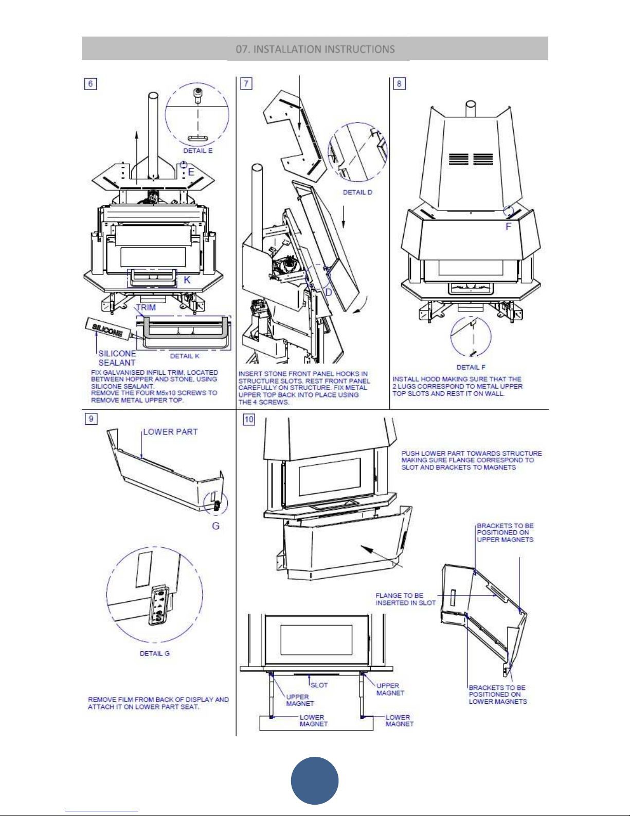
07. INSTALLATION INSTRUCTIONS
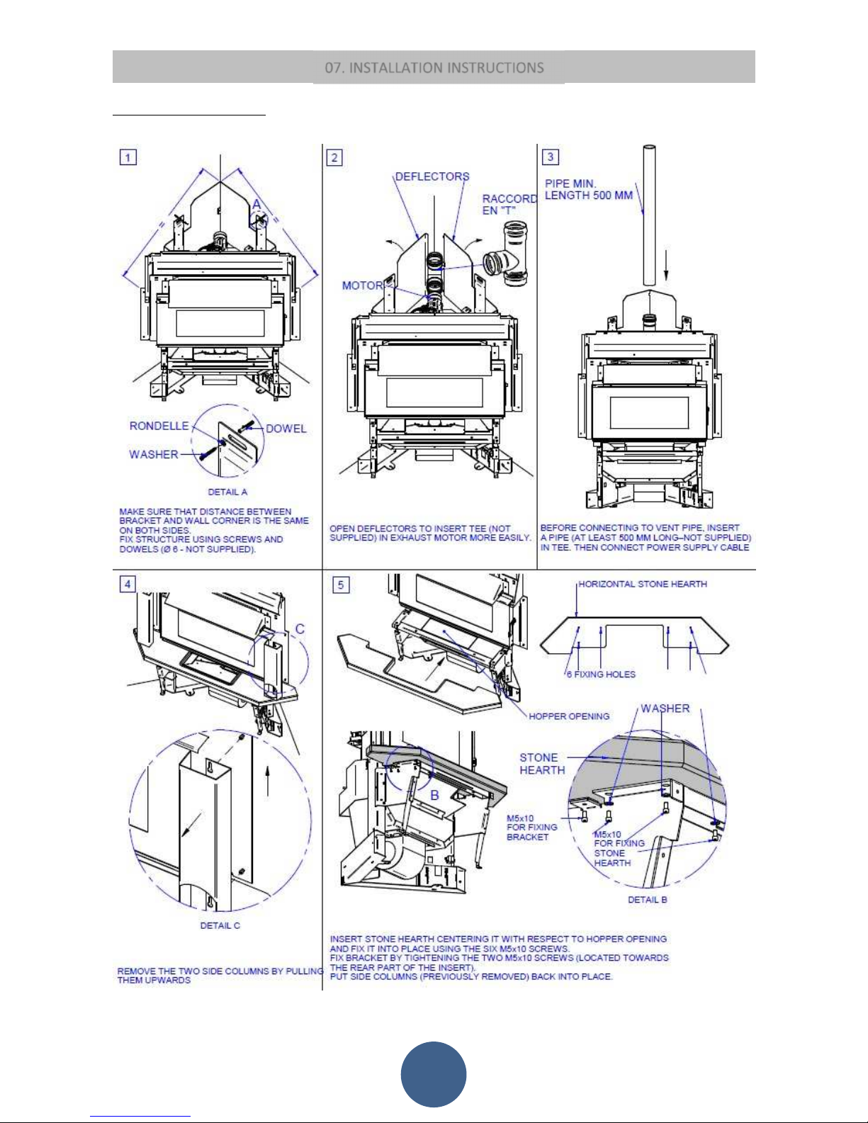
07. INSTALLATION INSTRUCTIONS
22
12kW STONE CORNER INSERTS
After making sure that the insert fits into the recess and there are a socket and a vent pipe
07. INSTALLATION INSTRUCTIONS
23
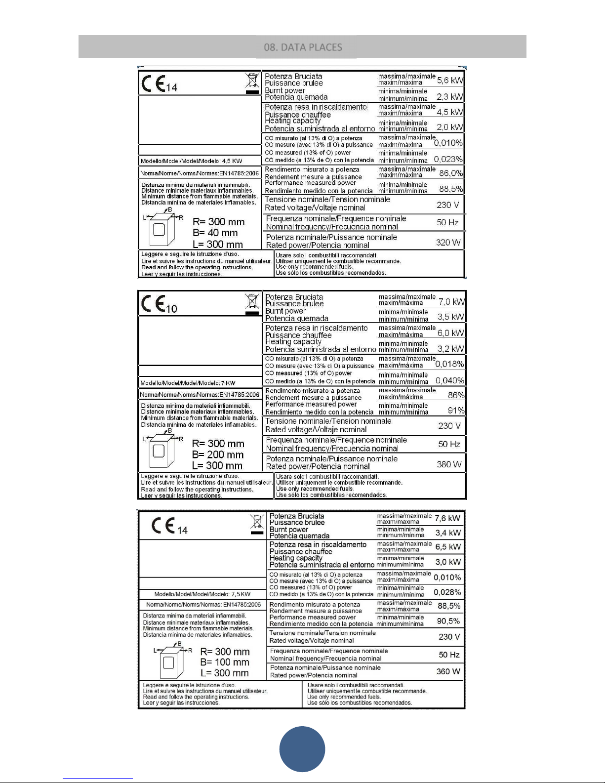
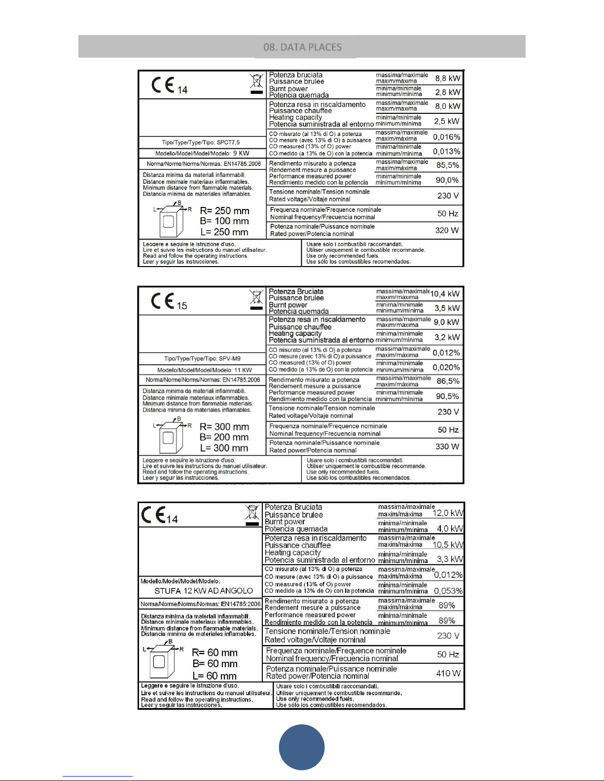
08. DATA PLACES
24
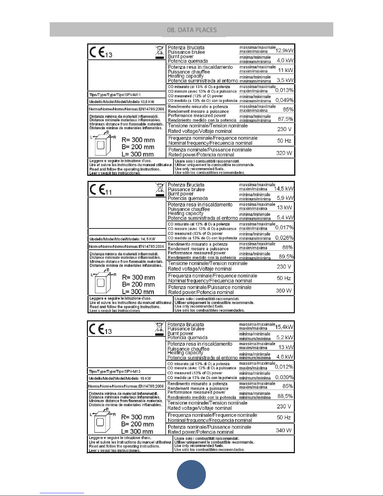
08. DATA PLACES
25
08. DATA PLACES
26
 Loading...