

Page 1
EUVISION
IMAGE TECHNOLOGIES
Service notes for Euvision splitter units
Split 16 4x4 / Split 16 Gold / 3xVision / Split 4 EU
Rev 1
06/03/2000
Page 2
Service notes for Euvision splitter units – Rev. 81 - 30/03/2000
Introduction
The following operations can be performed in case of malfunctions or unusual behaviour of the splitter units. Anyway,
splitter units are complicated powerful video devices built using advanced technology. Euvision strongly feels that it’s
very important that only qualified personnel open the top cover of the unit. Please observe the following precautions
when servicing the device in order to avoid injuries or damages the device itself:
• Always keep the main power cord disconnected from the mains when the top cover is open
• Always work in a static-free ESD protected area
• Use grounded soldering / de-soldering irons when replacing components on the main board
• Always use a marker to paint a dot on trimmers to be adjusted, so that you can bring them back to their starting
position in case of mistakes
How to read this guide:
This guide uses an easy to read structure to allow you promptly identify the fault and fix it. The following example
explains the various sections of each fault report. In the next pages you will found a complete list of all the known
faults.
Symptom: here you will find a detailed
description of the symptoms identifying the
problem.
Problem: here you will find a brief list of the
causes which make the problem arise
Solutions:
A detailed list of fixes, workarounds or things to try to solve the problem can be found here.
Contacting Euvision:
In case your symptom is not reported here or the listed solutions do not solve the problem then please contact Euvision
for servicing. Should you need any spare parts then please contact Euvision as well. Original spare parts ensure your
Splitter unit always offers its best to you.
Euvision S.r.l.
Rome - Italy - EU
Web: www.euvision.com
E-mail: info@euvision.com
Photo with visual information
Page 2 of 15
Page 3
Service notes for Euvision splitter units – Rev. 81 - 30/03/2000
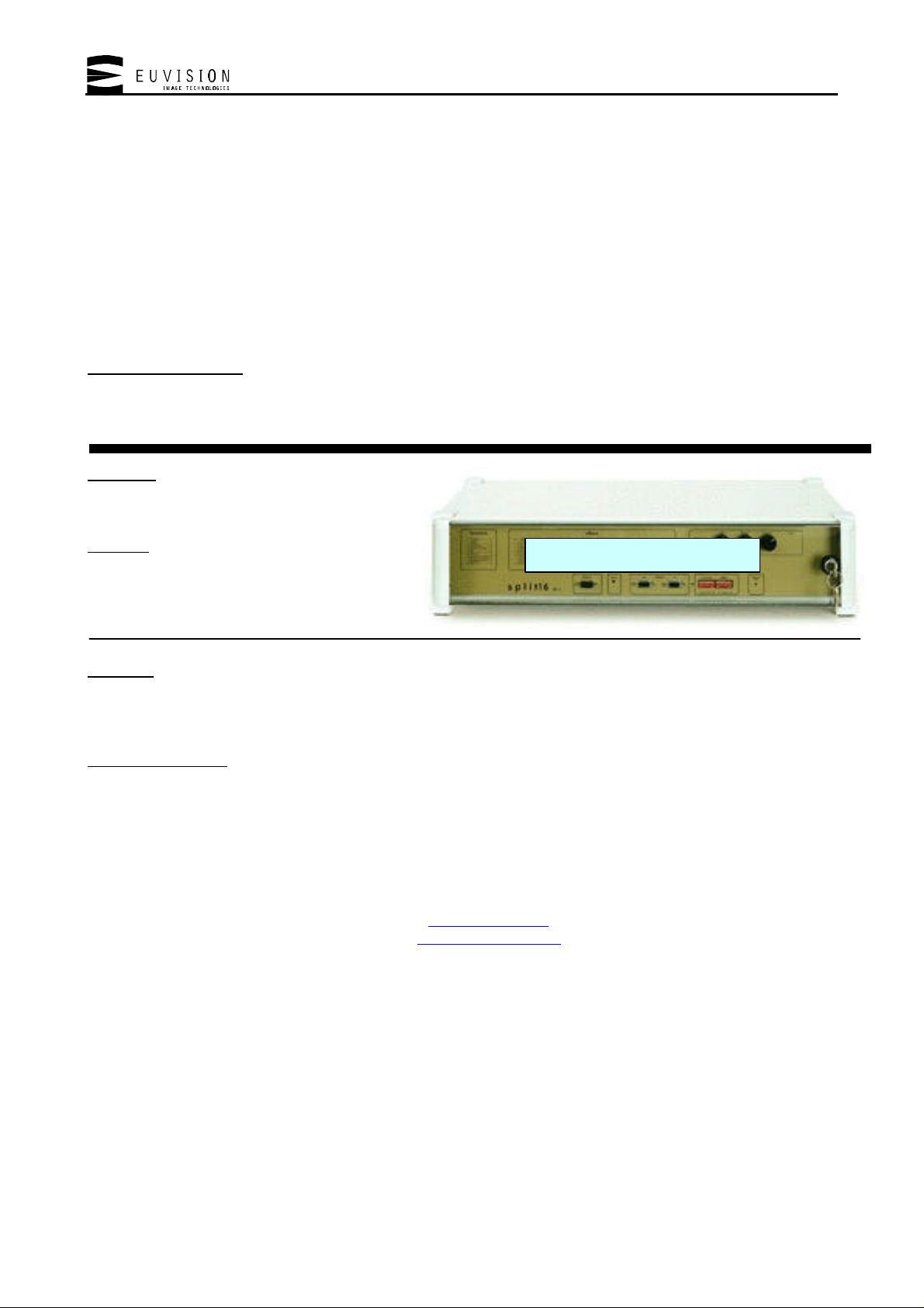
all monitors show a black screen, the
unit seems to be dead.
Problem: this may be caused by several
problems. Please check the following list
Power switch and fuses
Composite/S-VHS switch
Solutions:
• The unit is not powered. This can be easily verified: if the unit is operational then both the lights on the front panel
are lit.
ü Check the power switch on the rear
ü Try changing the power cord
ü Check the two fuses near the power switch. Please replace with exactly the same type of fuse.
ü Verify your power line. Try connecting another appliance to the same power outlet to verify that the power is
effectively present. Please remember that the splitter’s power supply must be in the range from 110 to
240VAC with 50 to 60 Hz.
• The monitors are not powered. Videowall systems are built of several monitors, each of which drains power from
the mains. If all of them are turned on at the same time then the power drain (which is bigger in the power on
phase) can make safety switches engage, turning the Videowall immediately off.
• The image is present but too dark to be seen. Try adjusting the three pots on the front panel of the unit to their
middle position. If this is the problem then the image should appear.
• The unit is set to operate in RGB mode. Check the dip switches on the front panel to see if the RGB mode is
selected. When this mode is turned on then the video input used is the RGB one, located on the front panel, while
when it’s off then the video decoder inputs, located on the rear panel, are used.
• The unit is set to operate in the wrong video mode. The video decoder of the unit has a switch which lets the user
select between a composite and S-VHS input (which are both located on the rear panel). Try pushing the
composite/S-VHS switch. If the wrong input is selected then doing this should solve the problem
• The video input is missing. Try connecting the video signal directly to a monitor instead of connecting it to the
splitter. Or, better, try connecting a test signal coming from a surely working test pattern generator to the video
input of the splitter. With this operation you can verify that the video signal entering into the splitter is effectively
present. If it is not then try replacing the video connection cable coming from the video source or refer to the user
manual of the video source itself.
• The monitor input is set to the wrong input. Check that input selection is correct. Most monitors have a rear switch
which selects the input, while others have an On Screen Display; in the latter case please check the monitor’s user
manual. Another problem could be with the priority setting of the monitor. If priority is set to a different input than
RGB and this input is fed, the monitor displays the prioritized input so in this case you should disconnect the input
or change the priority.
• The power supply of the unit can be broken or defective. Open the top cover of the unit and use your tester to check
the voltage of the supply lines going from the power supply to the main board. These voltages are: +5V, +12V and
(only used for 3xVision and Split 4EU) –12V. If one of these power lines dropped at zero volts then try replacing
the power supply unit (contact Euvision for spare parts)
• The power supply connector can be defective. Check the output connector of the power supply. The heat can loosen
the connections. If necessary, replace the connector and increase the size of the cables bringing power to the main
board. This is a rare case and can verify only on old pre-series models.
RGB input
Dip switches
Output connector
Power supply
Control pots
Page 3 of 15
Page 4

Service notes for Euvision splitter units – Rev. 81 - 30/03/2000
• The video decoder can be defective. Try bypassing the video decoder by plugging an RGB video source in the front
panel connector and by switching to RGB mode using the dip switches on the front panel. If this solves the problem
the video decoder have to be changed. Please contact Euvision for spare parts.
Page 4 of 15
Page 5
Service notes for Euvision splitter units – Rev. 81 - 30/03/2000
Symptom: one of the outputs shows no image (black screen)
Problem: this may be caused by several problems. Please check the
following list
100nF 0805 capacitors
Solutions:
• The output cable can be defective. Try replacing the RGB output cable. If this solves the problem then the wire of
the cable can be internally broken. Anyway most often the problem can be fixed by checking the connections inside
the DB9 connector ends of the cable. This is especially true for the video sync wire, since monitors engage a screen
saver protection when no sync signal can be found.
• The monitor can be defective. Try plugging the cable of a working output into the monitor with no image on it. If
the image appears then you have to replace the output cable, otherwise (in case the image does not appear) the
monitor is probably defective. Try checking the monitor’s input selection, power supply cable of the monitor and
its fuses and/or power switch.
• The output board of the splitter unit can have loosen contacts. Check and eventually renew loosen contacts on the
connector board, which is mounted right behind the rear panel of the unit.
• The RGB D/A converter of the output is defective. Use a chip extractor tool to remove the faulty IC (BT121)
integrated circuit then insert a new one in its socket (contact Euvision for spare parts).
• One or more of the 100nF SMD coupling capacitors around the RGB D/A converter opens or goes short-circuit.
Replace all the three capacitors with 100nF 0805 parts. This problem is a rare one and verifies only on older
models of the unit (contact Euvision for spare parts).
BT121
DB9 connectors
Page 5 of 15
Page 6

Service notes for Euvision splitter units – Rev. 81 - 30/03/2000
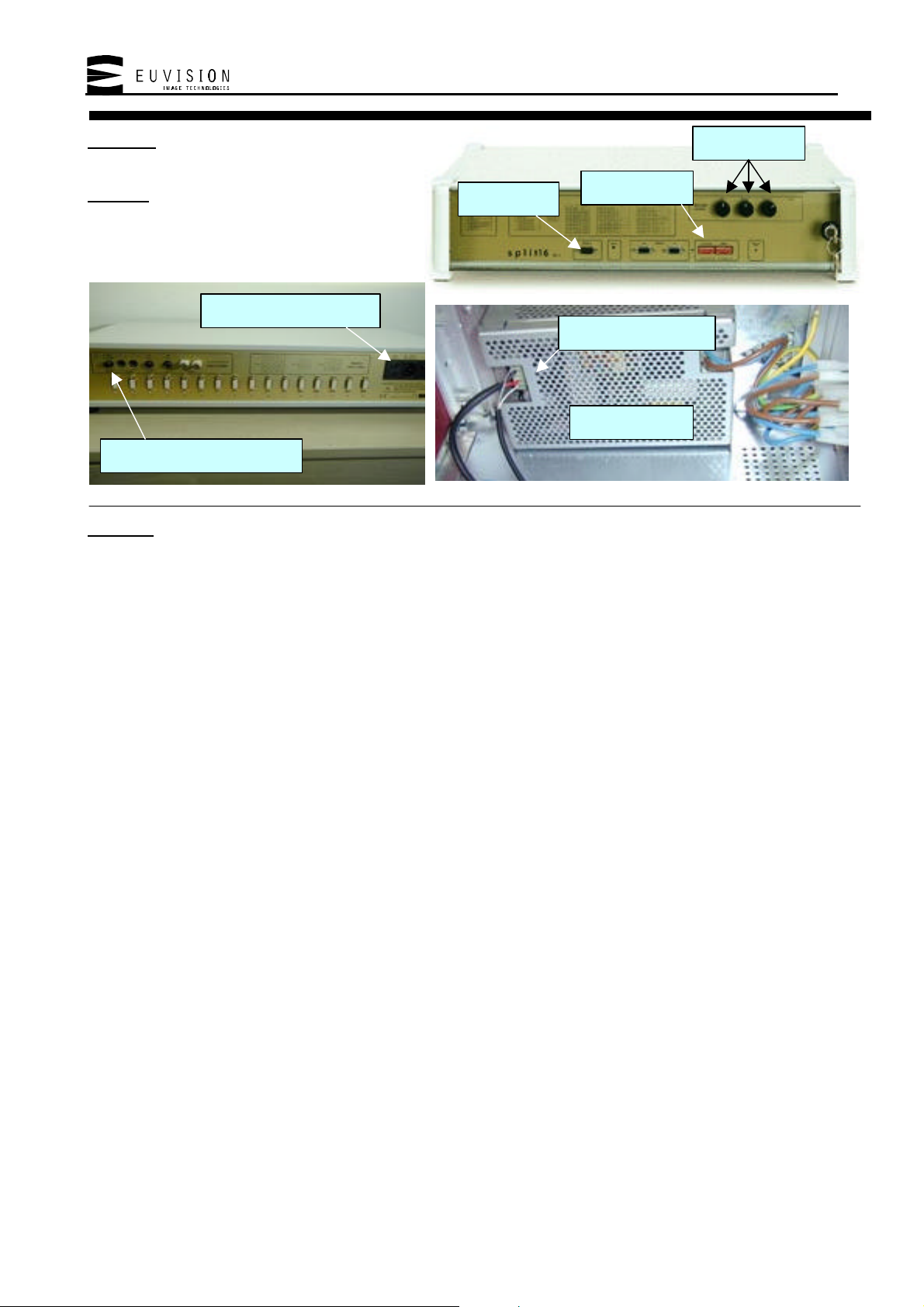
Symptom: two of the outputs show a black screen. The outputs are one
of the following couple: 1&2, 3&4, 5&6, 7&8, 9&10, 11&12, 13&14 or
15&16
Problem: sync signals are shorted or the sync generator integrated
circuit which drives the outputs in couple of two is defective and
must be replaced.
Solutions:
• Check if the sync signal on one of the two cables is shorted. Since the sync signals are shared between two outputs
shorting one output means shorting also the second.
• Try connecting the two cables one at time and check if the video is output. If this is true and the cables are working
check if there’s a short or a very low impedance on the input of the monitor and that the pinout of the cable is
correct.
• The driver of the sync signals could be broken. Replace the 74HCT244 integrated circuit located on the main board
near the border, on the power supply side of the unit. This IC is the driver for all the 16 outputs.
74HCT244
Page 6 of 15
Page 7

Service notes for Euvision splitter units – Rev. 81 - 30/03/2000
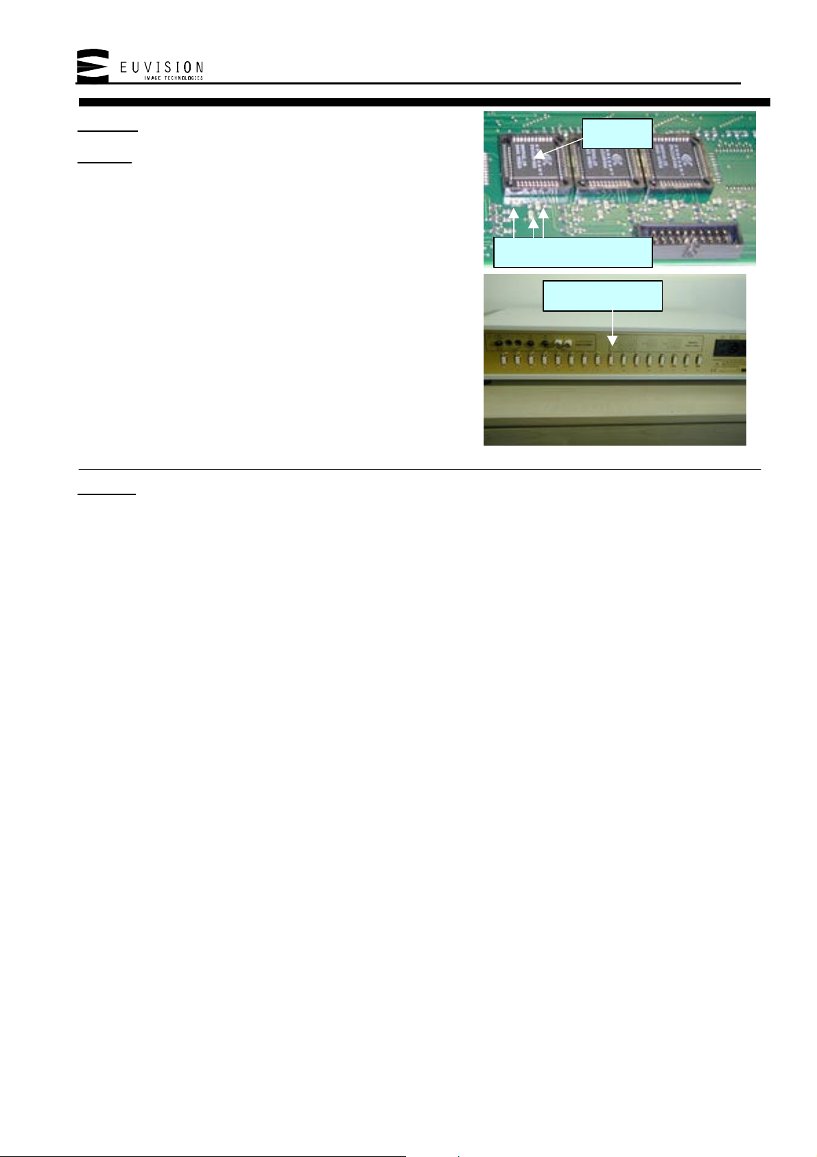
M12 programmed device
Symptom: the lower row of monitors shows coloured pixels superimposed
over the image
Problem: supply voltage is not correct or the M12 programmable
integrated circuit does not work correctly.
Output voltage trimmer
Solutions:
• The first thing to try is to check the power supply unit, since the +5V supply line may have dropped below +4.8V,
causing the problem. If this is the case then the problem shows itself when the device is powered, but if the voltage
dropped too much then the problem may remain visible even after power on. In either case the problem can be
fixed in the following way:
ü Firmly connect a voltage meter to the +5V supply line coming from the power supply
ü Turn the unit on
ü Wait some minutes to let the power supply rise its temperature. Meanwhile find the voltage regulation screw
located on the power supply.
ü Now turn the screw slowly and smoothly to make the tester read +5.1 +/- 0.02V
• If the above does not solve the problem then use a chip extractor to remove the M12 integrated circuit and then
replace it with a new one (contact Euvision for spare parts)
Page 7 of 15
Page 8

Service notes for Euvision splitter units – Rev. 81 - 30/03/2000
Symptom: one of the outputs lacks of a base colour (red, green or blue)
Problem: this may be caused by several problems. Please check the
following list.
Pads under the BT121 socket
DB9 output connectors
Solutions:
• The monitor is defective. Try feeding a test signal directly into the monitor to verify this. If the base colour does
not appear, even using a well-known test signal, then the monitor must be repaired or replaced.
• The RGB cable is damaged. Try replacing the RGB cable or verify the cable connections at both ends. This is
especially true for the Red, Green and Blue signal wires.
• The output connector of the splitter may have loosen contacts. Check the output connector board mounted right
behind the rear panel of the unit.
• The RGB D/A converter integrated circuit which drives the output is broken or defective. Remove the BT121
component with a chip extractor and replace it with a new one (contact Euvision for spare parts).
• The solder pads connecting the socket under the BT121 integrated circuit to the main board may have loosen
contacts. Extract the BT121 component using an appropriate tool, then re-solder the socket and insert the
component back.
Page 8 of 15
Page 9

Service notes for Euvision splitter units – Rev. 81 - 30/03/2000
Symptom: one of the three base colours (red, green or blue) is
clearly distorted on all the outputs.
Problem: the data of the video A/D converters which digitize
the incoming image to be processed do not match the ones fed
into the device’ raster memory. This is caused by the buffering
circuitry surrounding the A/D converter, which is defective.
74HCT244 colour buffers
Solutions:
Replace one of the 74HCT244 integrated circuits which surround the A/D converters. There are three converters and
three buffers. One each for the red, green and blue chroma signals.
Page 9 of 15
Page 10

Service notes for Euvision splitter units – Rev. 81 - 30/03/2000
Symptom: the image luminance and contrast vary on their
own; the image gets distorted or too dark; colour gets
distorted. The quality of the image is not the one shown when
the same video source is connected directly to a monitor.
Problem: copyright protected material is encoded with a
special video protection called “MacroVision” to prevent its
illegal duplication. Video Tapes, Satellite transmissions and
DVD are most likely MacroVision protected. This
modification is only needed on old models.
Solutions:
• The following modifications to the main board must be done:
ü Replace the 47k resistor marked in the picture with a 68k one.
ü Parallel the 1nF capacitor shown in the picture with a 47pF capacitor.
• If necessary replace the integrated circuit shown in the photo with a “CD74HC221E” built by Harris
semiconductors. WARNING! the integrated circuit must be the brand/model specified: no other similar or
equivalent integrated circuit will replace this one (contact Euvision for spare parts).
1nF capacitor
47k resistor Harris CD74HC221E
Page 10 of 15
Page 11

Service notes for Euvision splitter units – Rev. 81 - 30/03/2000
Symptom: after some operation time, black bands become visible on
the screen, disturbing the image.
Problem: the integrated circuit marked IC2 on the video decoder
reaches a temperature at which its operating parameters vary.
C38 IC2
Solutions:
Use a screw driver tool to slowly and smoothly adjust the P3 variable resistor (47k) shown above, turning its screw
toward the C38 capacitor.
P3
Page 11 of 15
Page 12

Service notes for Euvision splitter units – Rev. 81 - 30/03/2000
Symptom: the white temperature of the Videowall system is different from
area to area.
Problem: this happens when 4 or more Split 16 units are connected
together to create large Videowalls. The video decoder used for the
Split 16 units has a preset trimmer to adjust the white temperature;
but, due to the target this decoder board is addressed to, a rough
adjustment only is done on this trimmer by the producer before
shipping them to Euvision.
Gain trimmer
P1
Solutions:
Use a screw driver tool to slowly and smoothly adjust the P1 variable resistor shown above, turning its screw to
compensate the colour temperature of the other units. Further fine adjustments can be done using the gain trimmer
present on the front panel of the splitter unit.
Page 12 of 15
Page 13

Service notes for Euvision splitter units – Rev. 81 - 30/03/2000
Symptom: the image is cut on the left and right side.
Problem: this happens when the trimmer P7 of the video decoder is not
correctly adjusted. Before adjusting this trimmer try adjusting the
screen geometry and verify that the display really lacks of a part of the
image.
P7
Solutions:
Use a screw driver tool to slowly and smoothly adjust the P7 variable resistor shown above, turning its screw to widen
the visible portion of the image.
Page 13 of 15
Page 14

Service notes for Euvision splitter units – Rev. 81 - 30/03/2000
Symptom: the black level of the image is not satisfying.
Problem: the clamping level of the video decoder is not set at the
correct voltage level. Since this problem is now fixed during the
decoder’s production process, this modification may be needed only
on older models of the Split 16 unit. Contact Euvision for spare
parts.
Solder points
R66
C46
Solder point
Solutions:
Follow these steps:
ü Get three 10k +/-1% resistors and solder one lead of each to the same wire. Refer to the schematic diagram shown
above.
ü Connect the other end of the wire to the R66 lead facing C46. Refer to the above photo.
ü Connect the free ends of the resistors to the following points (refer to the above photo):
a) the R96 lead facing the edge of the board
b) the R97 lead facing R130
c) the R98 lead facing R130
Page 14 of 15
Page 15

Service notes for Euvision splitter units – Rev. 81 - 30/03/2000
Symptom: the device works correctly, but cannot be controlled using a PC
compatible computer.
Problem: this may be caused by several problems. Please check the following list.
Serial port settings
Solutions:
• The serial connection cable may be defective. Try replacing it. If this solves the problem then the cable can
probably be repaired by verifying the connections at both ends.
• The serial cable looses data.
ü The cable has a maximum data-safe length. Use the shortest possible one.
ü Please note that the serial cable is subject to interference caused by other devices. Although this is not likely to
happen, try changing the path of the cable going from the PC to the splitter unit. Avoid possible
electromagnetic sources like radio transmitters, huge power supplies, high voltage lines, cellular phones and so
on. Also avoid rolling up unused portions of the cable, since the spiral form it assumes may form a coil which
rejects those frequencies at which data flows inside the cable.
• The PC is not correctly configured to send data through the serial cable to the splitters. Verify that your serial port
works correctly by, for instance, connecting another device to it.
• The software is not correctly configured to drive the splitter units. Ensure that the setup page of the Videowall
manager software shows the correct serial port setting. If you don’t know to which port the splitter unit is
connected to, then try selecting COM1 and run a splitter effect from the Effects page. If nothing happens try the
very same thing with the COM2 port and so on.
• The software can be defective, although improbable. Euvision always strives to offer the best to its customers,
improving its products and the relative driving software. It may happen that a newer version of the driving
software, published on the world wide web, accommodates modifications to the splitter firmware, which have been
made in order to improve the product. Try using the software which originally came with your splitter unit instead
of using the one downloaded from the web. If this solves the problem then please contact Euvision for a firmware
upgrade of the unit. This will let you use newer software versions which may be incompatible with your current
firmware versions.
Page 15 of 15
 Loading...