

Page 1
E IPP 5000 User’s Manual
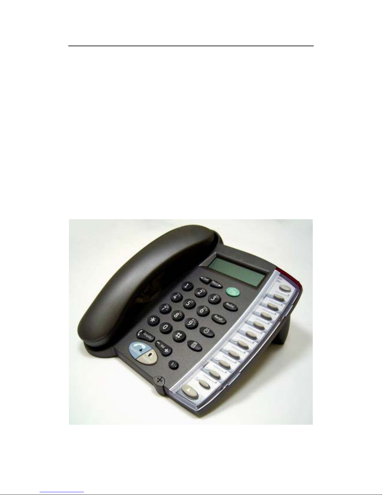
IPP 5000
User’s Manual
<Version: V1.0 >
Confidential Page 1 3/24/2009
Page 2

E IPP 5000 User’s Manual
Confidential Page 2 3/24/2009
Copyright © 2009 All Rights Reserved
Contents
1 OVERVIEW....................................................................................................................3
2 PACKING.......................................................................................................................3
3 SAFETY INSTRUCTIONS.............................................................................................3
4 INTRODUCTION TO IPP 5000......................................................................................3
5 PERFORMANCE INDICES ...........................................................................................4
6 NETWORKING MODE ..................................................................................................5
6.1 TYPICAL APPLICAT IONS ..............................................................................................5
7 APPEARANCE DESCRIPTION.....................................................................................7
8 CONFIGURATION DESCRIPTION................................................................................7
8.1 WAN CONFIGURATION ENVIRONMENT ........................................................................7
9 CONFIGURATION IN WEB MODE ...............................................................................9
9.1 LOGIN WEB ............................................................................................................9
9.2 WAN CONFIGURATION.............................................................................................10
9.3 SIP CONFIGURATION................................................................................................11
9.4 CODECS SETTING .................................................................................................17
9.5 SYSTEM SETTING ....................................................................................................18
9.6 DOWNLOAD SETTING ...............................................................................................20
9.7 ADVANCE SETTING...................................................................................................21
9.8 RESET SETTING.......................................................................................................23
9.9 CONFIG BACKUP......................................................................................................23
9.10 CONFIG RESTORE..................................................................................................24
10 DIAL MODEL.............................................................................................................24
11 TROUBLESHOOTING...............................................................................................25
12 DIAL PLAN AND IVR ................................................................................................25
12.1.1 Dial Plans......................................................................................................25
12.1.2 IVR................................................................................................................26
Page 3

E IPP 5000 User’s Manual
Confidential Page 3 3/24/2009
1 Overview
The popularization of the Internet has driven the rapid development of a wide variety
of IP-based applications. The IP telephone technology has become the major means for
operators to develop voice services. IP technology has become the core of the next
generation network (NGN).
With the rise of IP Phone technology the attacks on the security of personal,
confidential and enterprise information have also risen. Eutectics IP Phone technology
provides optional secure unbreakable encryption to address this need.
2 Packing
The IPP 5000 is packed with all necessary accessories to bea able to make use of it
right out of the box. The packing box contains and IPP 5000 IP phone (including handset,
cord and base unit), one IPP 5000 power adapter and user’s manual.
3 Safety Instructions
To ensure your safety and safe use of this product, please pay attention to the following
items:
Follow the instructions in the user’s manual.
Keep the device far away from chemicals, excessive moisture and heat.
Store/use the equipment in dry and well-ventilated environment.
Never open the chassis lest the device is short-circuited or damaged.
OPENING the Chassis or attempting any repairs will VOID your WARRANTY
4 Introduction to IPP 5000
The IPP 5000 application runs on POSIX the most popular LINUX embedded
operating system and a high speed RISC CPU and dedicated DSP hardware. The
platform is extremely flexible and applicable to a wide variety of needs.
Basic features:
One 10/100 BASE-T WAN port, used to connect broadband data network
Page 4

E IPP 5000 User’s Manual
Confidential Page 4 3/24/2009
One 10/100 BASE-T PC port, Bridged to the WAN port.
Supports either DHCP Client or static IP address assignment
Supports 802.1Q VLAN and VLAN Tag for QOS
Mute (no voice) packet compression and comfort tone re-generation technology.
Self-adaptive jitter buffer cache ensures smooth voice even with lossy packet
networks
Lost-packet compensation guarantee mechanism enhances voice quality.
Built-in Internet gateway function
Easily-configured HTML based Console.
Supports remote configuration via Web mode and remote software downloading or
software upgrades
5 Performance Indices
Description of Product Model(s)
IPP 5000 SIP protocol
IPP 5000E CEALComm Proprietary Encrypted protocol
IPP 5000ES SIP protocol with CEALComm encrypted RTP
Physical Specifications
Power supply
AC/DC power adapter, 120 VAC/220 VAC to
DC output: 5V DC/1A
Power consumption < 10W
Weight About 1 kg
Reliability
System availability > 99.999%, MTBF > 100,000 hours, MT TR <
5 min
Ambient requirements
Working temperature 0°C ~ 50°C
Storage temperature -10°C ~ 50°C
Relative humidity 5% ~ 95%, non-condensing
Technical Specifications for the interface attribute gateway
Mute processing/four wave processing
RTP/RTCP voice channel
Voice compression algorithm G.711A/U, G.729, G.723 and G.726
Page 5
E IPP 5000 User’s Manual
Signal format: DTMF
Echo suppression: G.165/G.168
DTMF signal detection/generation
Compatible to the Internet protocols, such as TCP/IP, UDP, ARP, TFTP and ICMP
Secure Proprietary CEALComm DLDES Encryption (optional)
Supporting SNMP Version II
Compatible to IEEE 802.3 10BASE-TX Ethernet
Compatible to IEEE 802.3u 100BASE-TX fast Ethernet
6 Networking Mode
6.1 Typical Applications
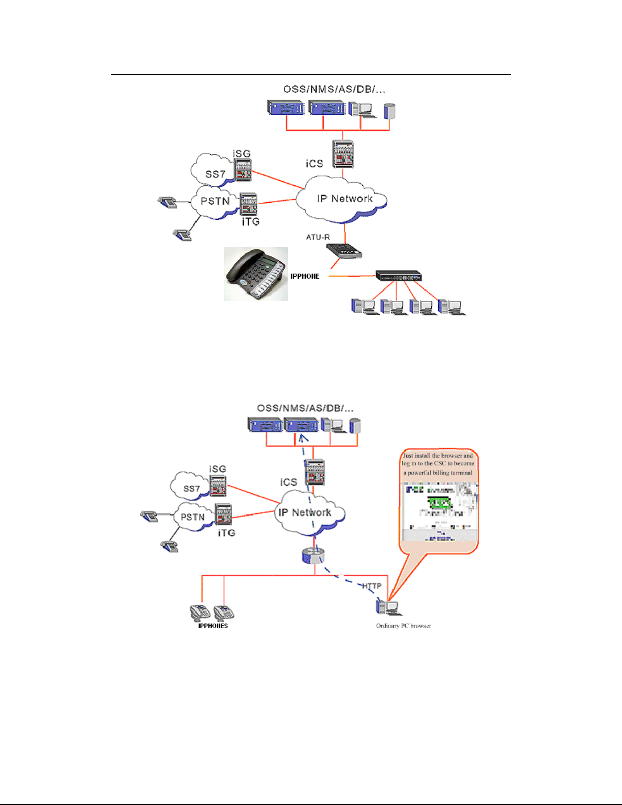
The IPP 5000 has an integrated Internet gateway so small enterprises can use the
10/100Mbps PC Ethernet interface to connect to their local PC and use the uplink port to
connect to the local Router, DSL Modem or Cable Modem.
The IPP 5000 also is the ideal access equipment for small and medium scale
enterprises with a local or remote SIP server (as shown in Fig.B). The uplink can be
connected to the ITSP (Internet Telephony Service Provider) network through an Ethernet
interface connected to the small switch or router.
The optional CEALComm DLDES Encryption technology makes the IPP 5000 a
unique device for use with either the Proprietary CEALComm Server (for the most highly
secure Government or Military applications) or to encrypt the SIP RTP payload (IPP
5000ES option) for secure Enterprise communication in a standards based environment.
Confidential Page 5 3/24/2009
Page 6
E IPP 5000 User’s Manual
Internet + VOIP System Architecture for Small-size Enterprise/Branch (Copper Cable DSL)
Fig. A
Operator IP Telephone Bar System Architecture (Catogory-5 Cable)
Fig. B
Confidential Page 6 3/24/2009
Page 7
E IPP 5000 User’s Manual
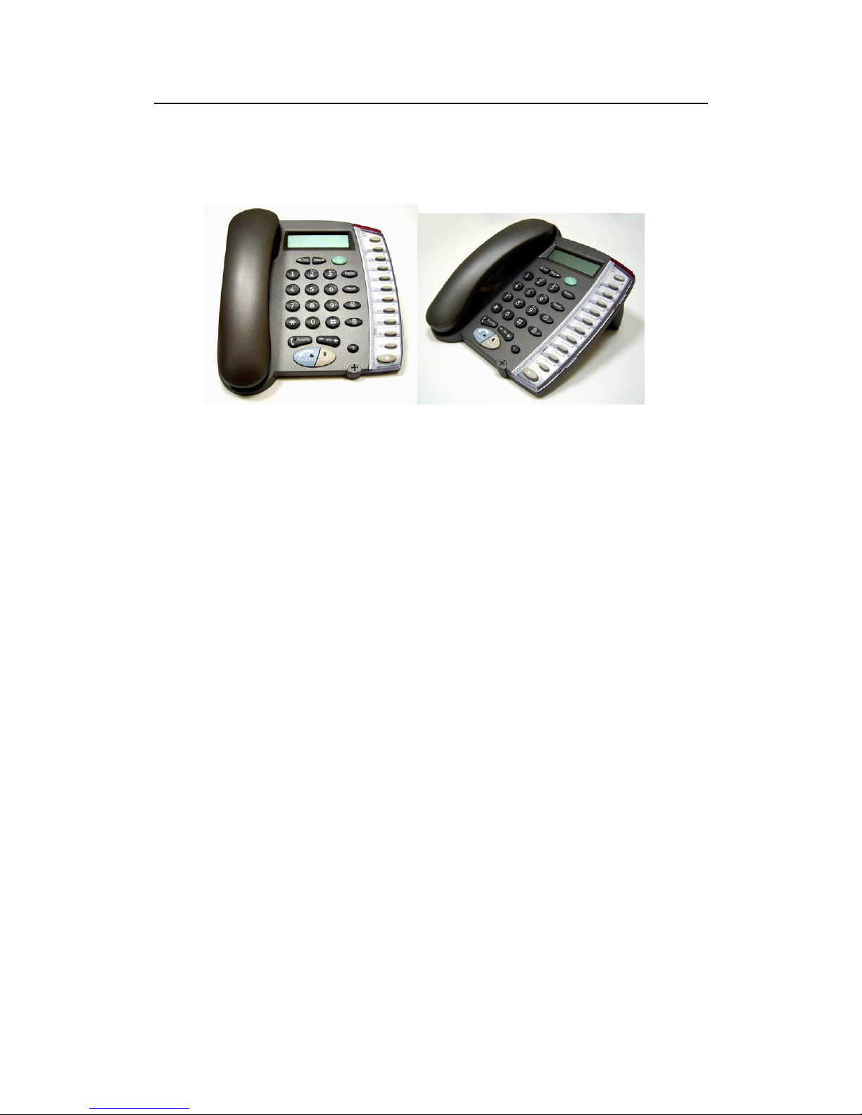
7 Appearance Description
8 Configuration Description
The IPP 5000 provides two ways to modify setup parameters: 1) Through PC
interface and 2) via the HTTP or WAN interface. Below describes how to enter the WEB
interface configuration parameter (refer to Chapter 9 WEB configuration interface
description) and also through HTTP or WAN interface (refer to Section 8.1)
8.1 WAN Configuration Environment
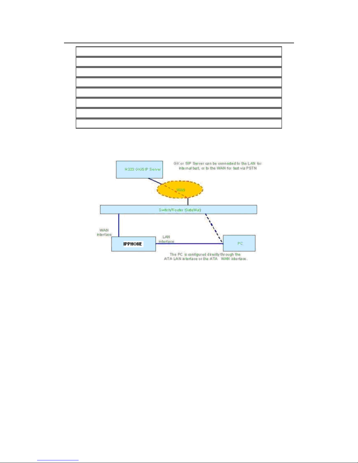
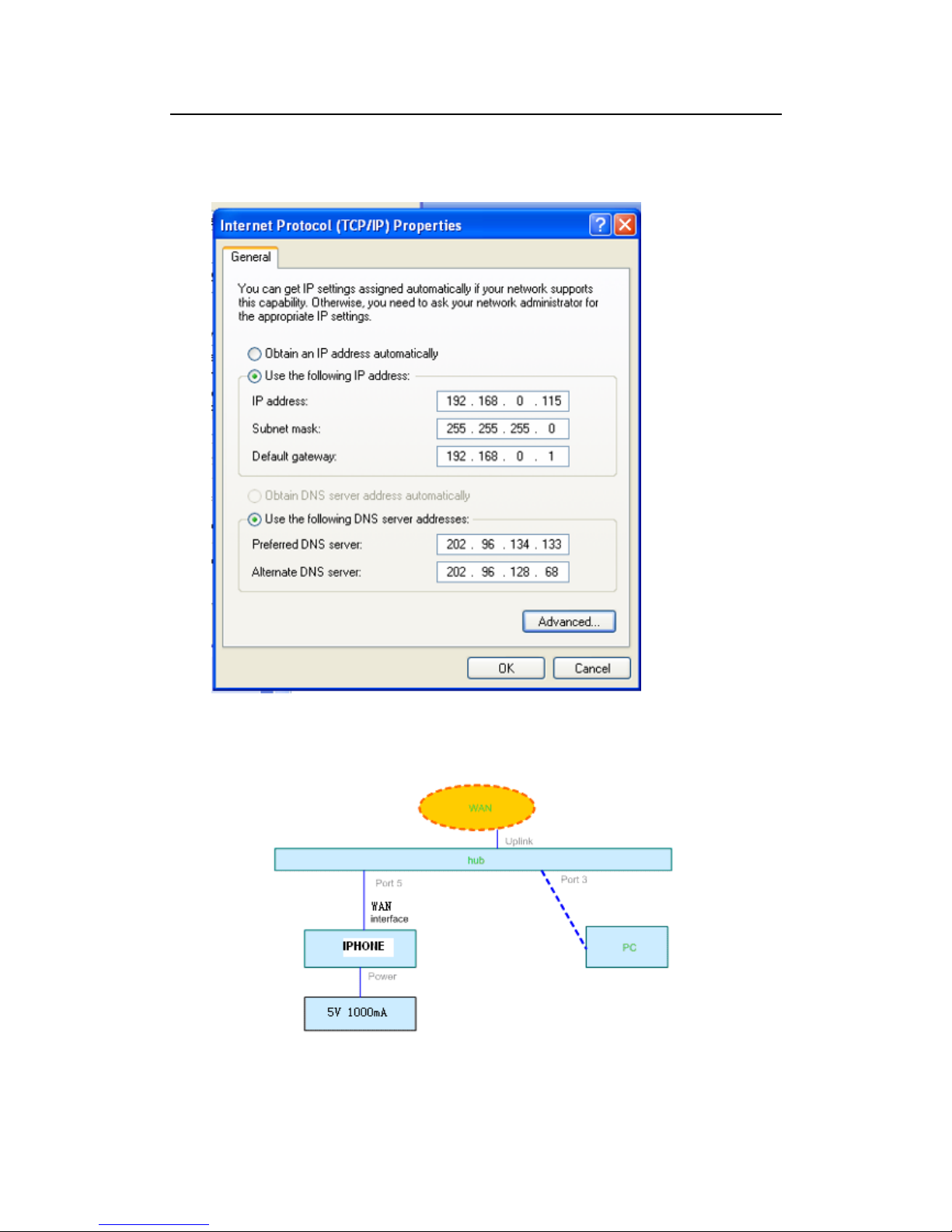
Configure the “TCP/IP Protocol” of PC according to Fig. 1 with the default IP
addresses of PC and IPP 5000 LAN in the same network segment.
Configure the device according to Fig. 2.
Use straight-through cables in the figure.2
Confidential Page 7 3/24/2009
Page 8
E IPP 5000 User’s Manual
After configuration, input the IPP 5000 default IP address in IE address bar . Each IPP
5000 will be allocated with an initial Lan IP address before delivery, assumed to be
192.168.0.200.
fig 1
Fig. 2
Confidential Page 8 3/24/2009
Page 9
E IPP 5000 User’s Manual
9 Configuration in WEB Mode
9.1 LOGIN WEB
Using the IPP 5000’s Wan or Lan IP address to login via the web.
Default Admin Username: admin
Default Admin Password: 888888
Default User Username: user
Default User Password: 888888
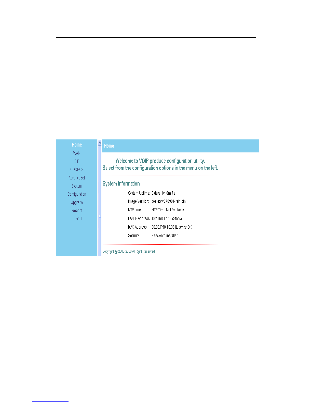
When login as admin user, will see like figure 3:
Fig. 3
When login as user,will see like figure 3:
Confidential Page 9 3/24/2009
Page 10
E IPP 5000 User’s Manual
Fig. 4
9.2 WAN Configuration
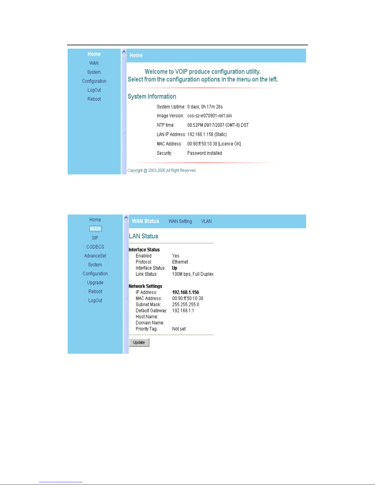
This page is the first page displayed when the device's web pages are accessed. It
shows how long the device has been running since its last reboot, the IP address the
device is currently using, whether or not the device is password protected, and also
displays the main application and downloader application firmware versions. In addition,
MAC address of the WAN port, and serial number of the device, if it has one, are also
displayed in this page.
Confidential Page 10 3/24/2009
Page 11
E IPP 5000 User’s Manual
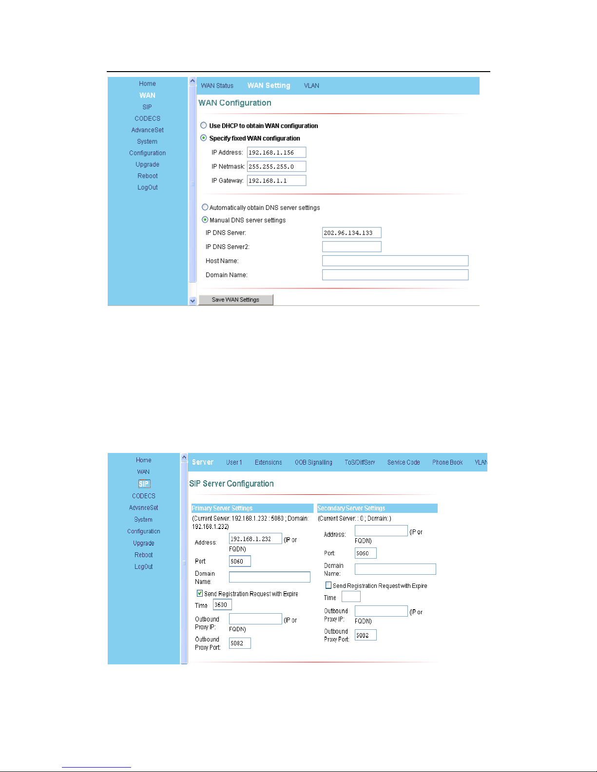
This page and its sub-pages are available on device that supports bridging and allows
viewing and configuration of the WAN interface status/settings. The default WAN interface
IP address is set to 192.168.0.200.Please note that any actions/modifications which alter
the topology of the Ethernet Bridge will result in the spanning tree protocol to relearn.
During this relearn period (may take up to one minute), HTTP access will be unavailable
on all bridged interfaces (including the PC interface).
9.3 SIP Configuration
This page allows configuration of the SIP server and endpoint settings.
Confidential Page 11 3/24/2009
Page 12

E IPP 5000 User’s Manual
Confidential Page 12 3/24/2009
Enter the address and port value of the SIP server. The address may be an IP
address or the name of the server. If no SIP server address is entered, the device will
attempt to self provision a SIP server using a DNS query. For this to be successful, ensure
that the DNS settings on the device include a DNS server address which is configured
with the SIP server address and will respond to the query, and the appropriate domain
name of the network.
If you wish to specify a special SIP domain name, you may enter the domain name
here. If no domain name is entered, the SIP domain name will be set to that of the network
(i.e. that which is obtained via DHCP, or specified on the WAN settings page, section 9.2).
The currently provisioned SIP Server and Domain are displayed beside "SIP Server
Settings" for informational purposes.
Select whether or not to send a Registration Request to the SIP server by checking the
box next to "Send Registration Request".
For the endpoint, set the dial plan to be used by all lines (refer to "Appendix D” for
details on the dialplan representation), and select the transport method to be used for SIP
signaling (either UDP or TCP).
For each line on the endpoint (NOTE: The IP Phone has a single line), enter the Line
Phone Number, Caller-ID Name, signaling port value, authentication Username and
Password, and select if AEC is to be performed on this line.
Press "Save SIP Settings" to save the new values.
Extensions
Page 13
E IPP 5000 User’s Manual
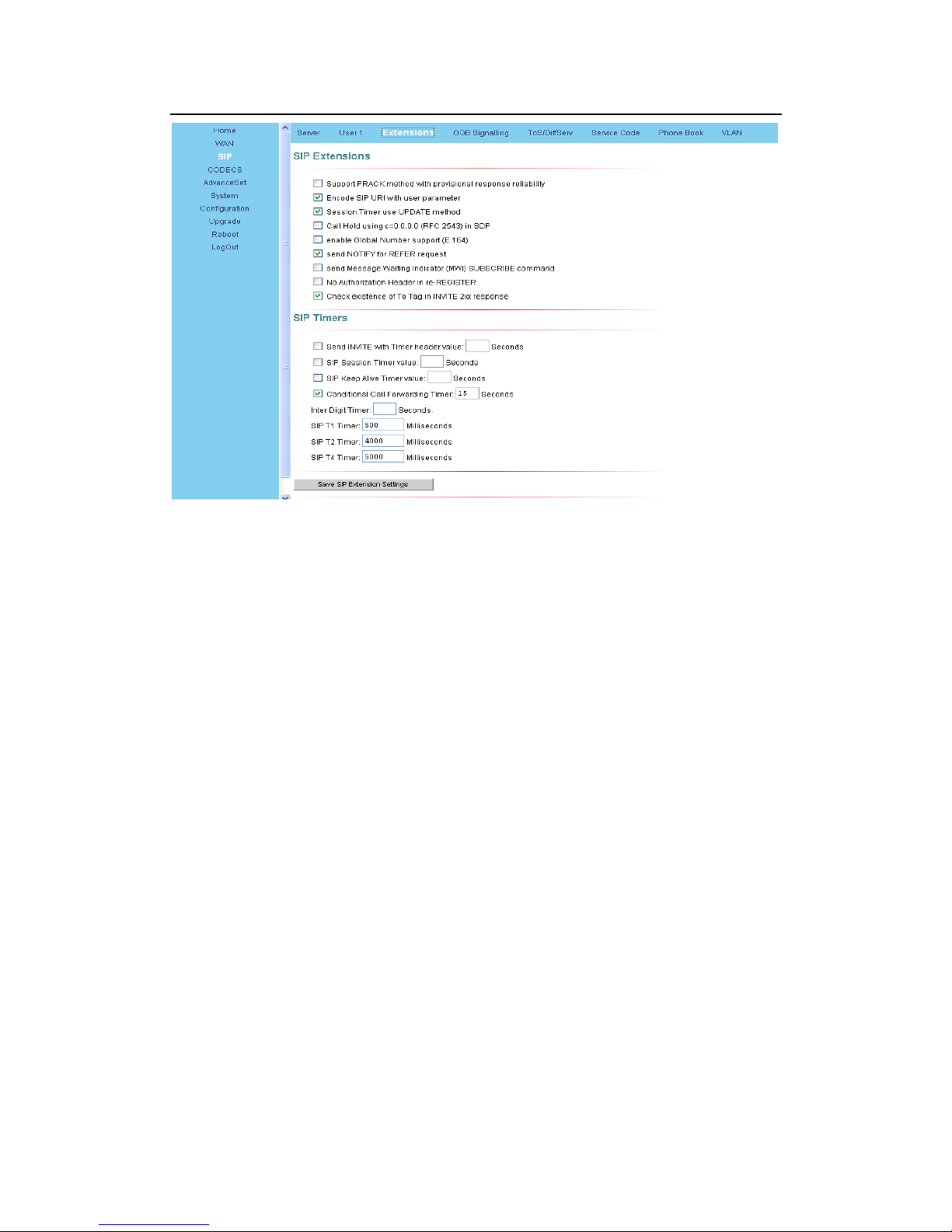
This page allows specification of the SIP signaling stack behavior under certain scenarios.
If you wish for the SIP stack to implement reliable transmission of provisional
responses according to RFC 3262 (using the PRACK method), check the option "Support
PRACK method with provisional response reliability".
If you wish for the SIP stack to include the user parameter "user=phone" in the SIP
URI header(s), check the option "Encode SIP URI with user parameter".
If you wish for the SIP stack to send INVITE messages with the "Timer" header field
present, check the option "Send INVITE with Timer header value" and enter the Timer
header value.
If you wish for the SIP stack to implement a session timer according to
"draft-sip-session-timer", select the option "SIP Session Timer value", and enter the
session time-out value.
Press "Save SIP Extension Settings" to save the new values.
Confidential Page 13 3/24/2009
Page 14
E IPP 5000 User’s Manual
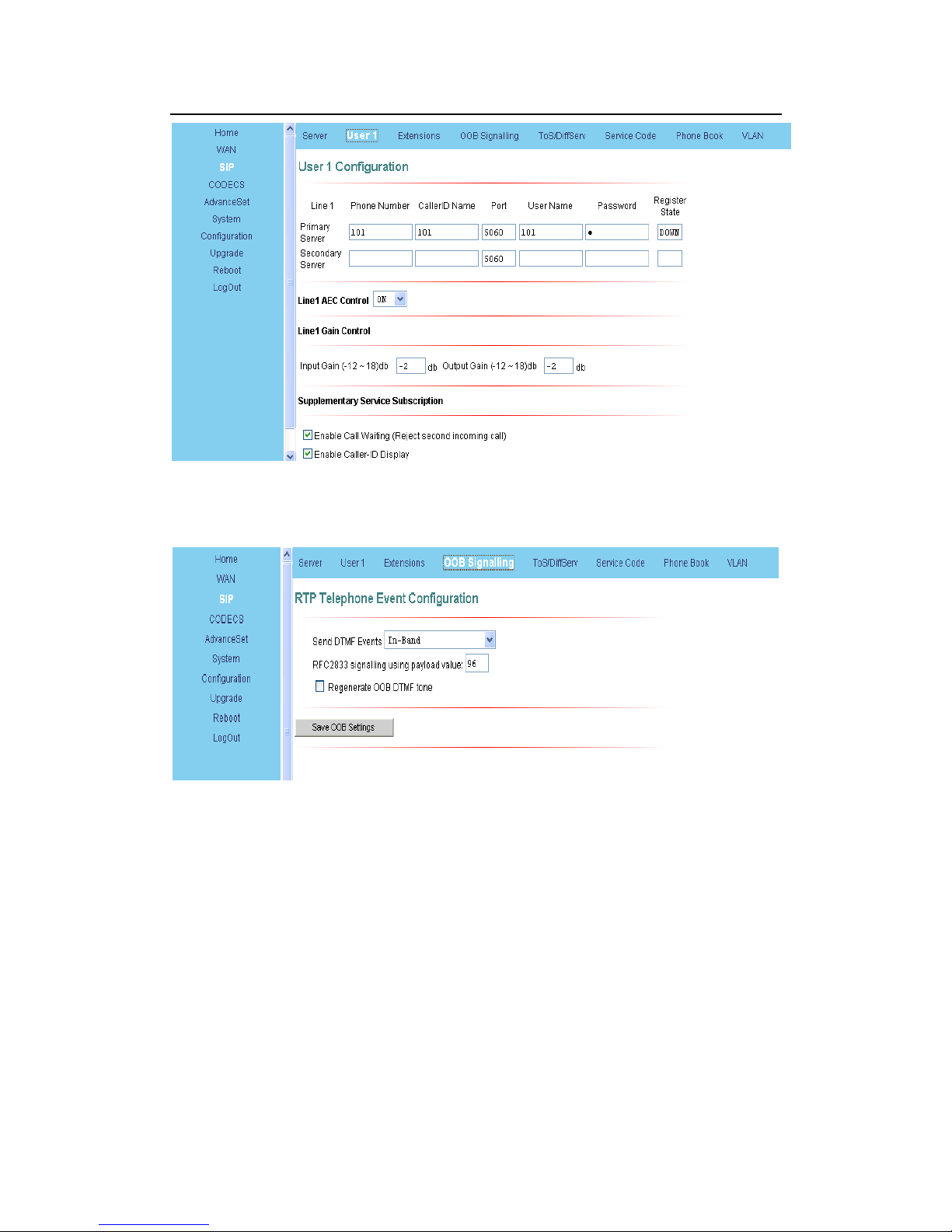
This sub-page allow the user to configure the d evice with phone number, caller ID,
username and password specified by the service provider.
This sub-page allows configuration of the out-of-band signaling options for SIP. Select
whether OOB telephone event signaling is to be done using the SIP INFO message, or to
be done via RFC2833 RTP signaling
Confidential Page 14 3/24/2009
Page 15
E IPP 5000 User’s Manual
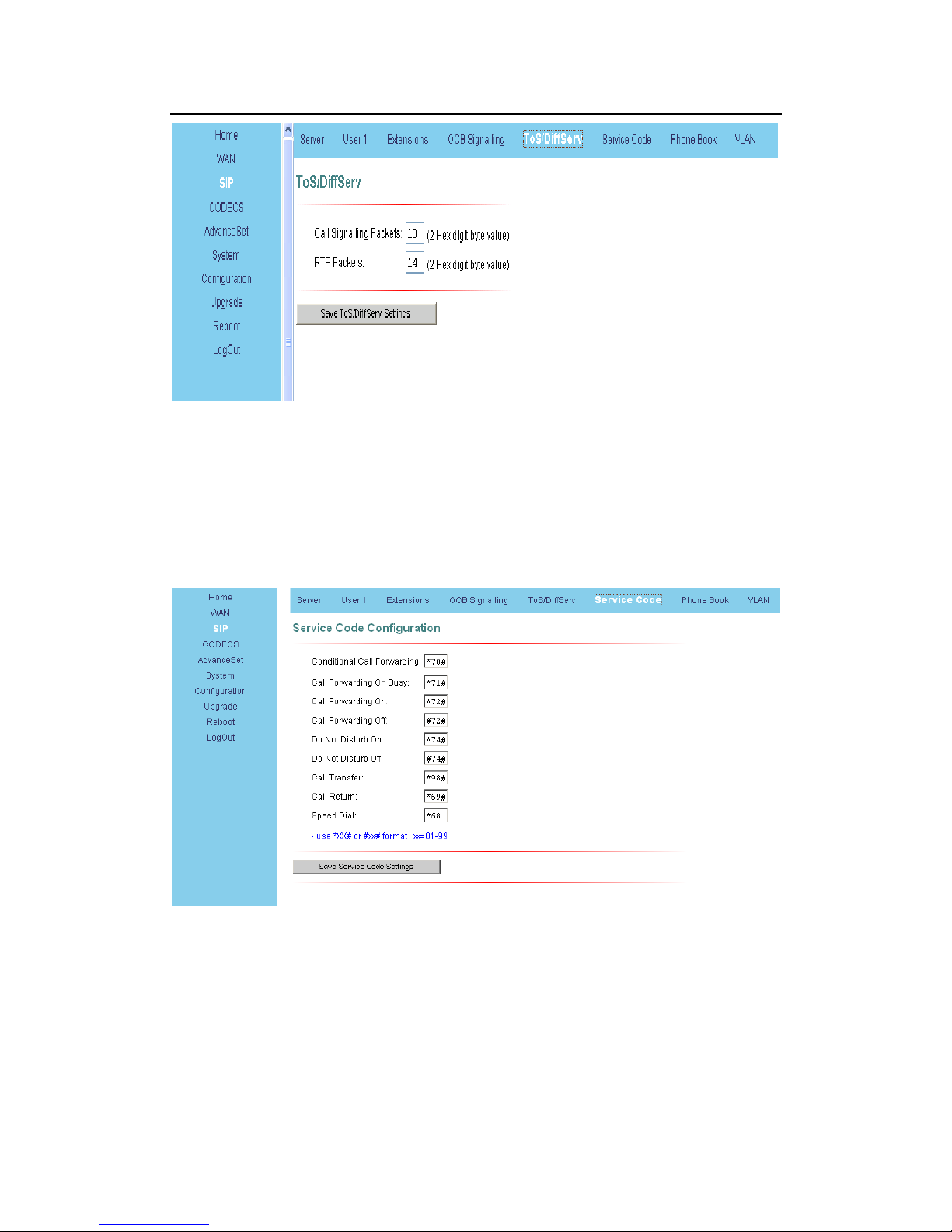
This sub-page is used to configure the T ype-of-Service/Diffserv byte values which are
to be used in the IP header of all transmitted SIP signaling packets and RTP packets. The
ToS/DiffServ byte values are entered as two-digit hexadecimal values. If no special
ToS/DiffServ value is to be used for a particular traffic type, enter "00" or leave the setting
empty.
Press "Save ToS/DiffServ Settings" to save these new settings.
You need to set the service code for using value add service. For example, I set the
service code as the above picture。
Condition Call Forwarding: (the call will transfer if no one answer)
a) Set forwarding number: pick up the handset(press *70# (then you will
hear the dial tone(press the forwarding number(then you will here three beeps
indicating setting finish。
b) Set the timeout: go to the “sip extensions(Conditional call Forwarding
Confidential Page 15 3/24/2009
Page 16

E IPP 5000 User’s Manual
Confidential Page 16 3/24/2009
timer” and set the timeout before forwarding,unit: second, and then active this
option.
c) Then the call will automatically transfer to the forwarding number if no one
answers the call in the timeout.
Call Forwarding on busy
Enable call forwarding on busy: pick up the handset(press *71# (then you will
hear the dial tone(press the forwarding number(then you will here three beeps
indicating setting finish, then all incoming call will forward to this number
automatically when the Phone is busy
Call Forwarding: (forwarding always)
This sub-page is used to configure Tones which applies in order to acknowledge users.
Dial Tone: The tone you hear when you pick up handset
Recall Dial Tone: The tone when you hold callee and prepare to make another call.
Confirm T one: The tone after you’ve set up some service, like DND (Do Not Disturb), Call
Forwarding, etc.
Ring Back Tone: The audible ringing you hear before callee picks up and answers your
call.
Busy Tone: The tone indicates the number you dialed is in busy now.
Reorder Tone: The tone you hear if you dial an invalid number or the call is not available.
Receiver-Off-Hook Tone: The tone to alert you to place the handset on-hook.
Message-Waiting-Indicator Tone: The tone to notify you to call for message box.
Call-Waiting-Indicator Tone: The tone to make you aware of the second incoming call
while you’re in conversations.
Ring
Page 17
E IPP 5000 User’s Manual
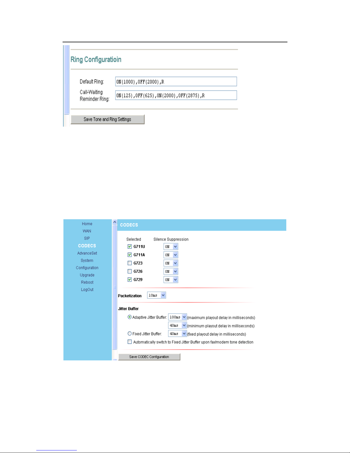
This sub-page is used to configure Ring Cadences required by Rings,
Call-Waiting-Indicator, and Distinctive Ring features.
1. Ring Configuration:
Default Ring: Default ring cadence when the phone rings.
Call-Waiting Reminder Ring: Ring cadence of Call-Waiting Reminder Rin g.
9.4 CODECS Setting
If the device is running one of the four VoIP applications, this page is available for
configuring the audio CODEC parameters, as well as the Jitter Buffer settings for the
CODEC decoders.
Enter which CODECs are to be supported.
Confidential Page 17 3/24/2009
Page 18
E IPP 5000 User’s Manual
Select which complex codec is to be supported. Due to memory limitations, it is not
possible to select G723 and G729 complex codec at the same time.
Select the packetization period to be used for each selected CODEC. For MGCP, a
range of packetizations may be provided for each CODEC (to be advertised in the
device's "capabilities" set).
Select whether Silence Suppression is to be supported for each CODEC.
The Jitter Buffer settings apply to all active CODEC decoders. You may choose
between an adaptive jitter buffer and a fixed jitter buffer. For an adaptive jitter buffer,
choose the maximum allowable playout delay (in milliseconds). For a fixed jitter buffer,
choose the fixed playout delay (in milliseconds).
Finally, select whether or not a decoder should automatically switch from an
adaptive jitter buffer to a fixed jitter buffer upon fax/modem tone detection. Adaptive jitter
buffers are sometimes detrimental to fax transmission over G711 CODECs if they have to
adapt too rapidly or too extensively due to inconsistent and widespread packet delays. In
these adverse network conditions, a fixed jitter buffer provides superior performance when
handling incoming fax transmissions over G711 CODECs.
Press "Save CODEC Settings" to save the new CODEC parameters.
9.5 System Setting
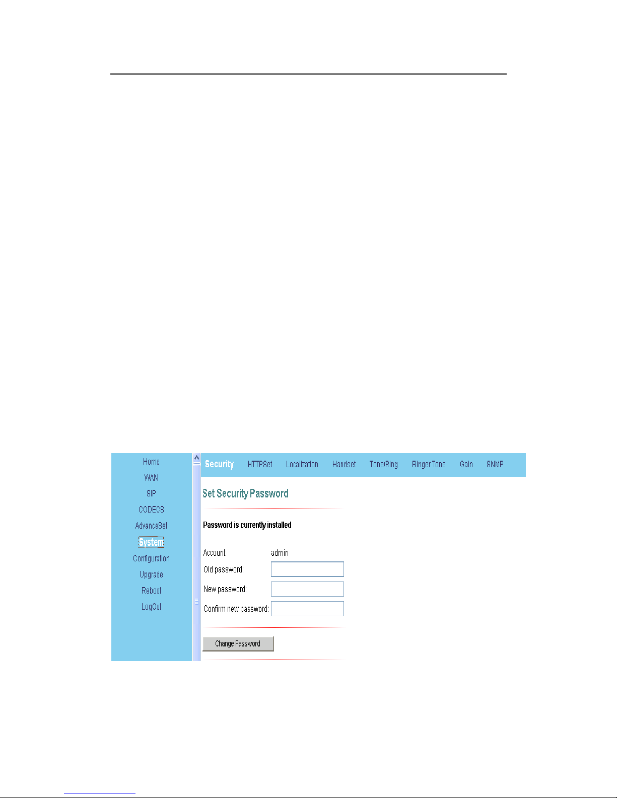
1. Set Security Password:
Click "System" item on the top menu.
Confidential Page 18 3/24/2009
Page 19
E IPP 5000 User’s Manual
Click "Security" on the left menu.
In Old password field, input old password , if you have it.
In New password field, input new password .
In confirm password field, input confirm password
Press "Change Password" button to save changes.
Timezone:
Find the current time from a list of cities.
Country Caller ID:
The caller ID can find out who's calling you and keep track of how often they call.
Users should set the country field according to their geographical location, otherwise the
Caller ID function might not work properly.
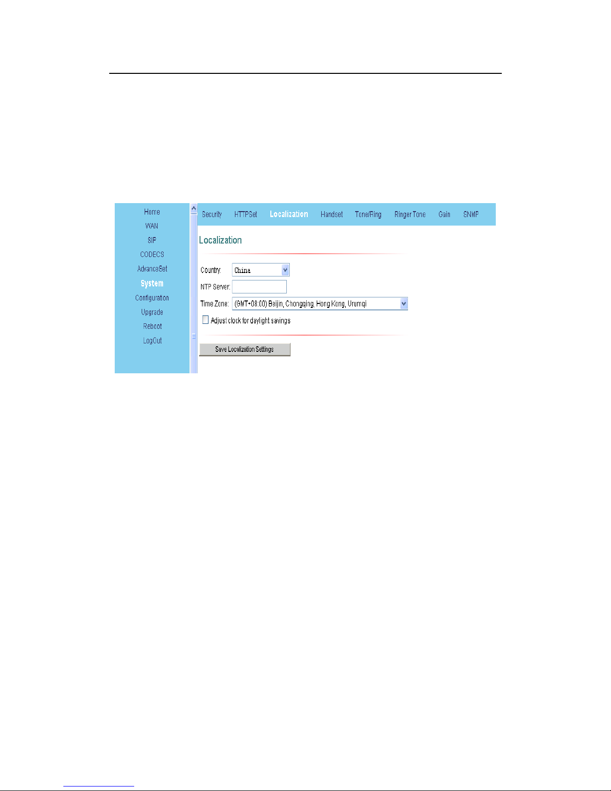
1. Timezone setting:
Click "System" on the top menu.
Click "Localization" on the left menu.
In NTP Server field, enter a NTP server IP address . If you want to use the default NTP
server, this field should be blank .
In Time Zone drop down menu, select one time zone .
In Adjust clock for daylight savings checkbox, if your country has daylight savings time,
you can enable it
Press Save Localization Settings button , then system will redirect to the web page of
reset.
Confidential Page 19 3/24/2009
Page 20
E IPP 5000 User’s Manual
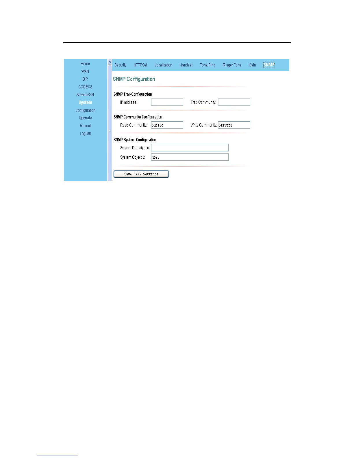
This sub-page is used for configuring the device's SNMP manager. Configure the
SNMP Trap Host IP address and community, the SNMP read and write community
parameters, and the SNMP System Description and System Object ID parameters.
Press "Save SNMP Settings" to apply the new values. These settings will only take effect
when the device is rebooted.
9.6 Download Setting
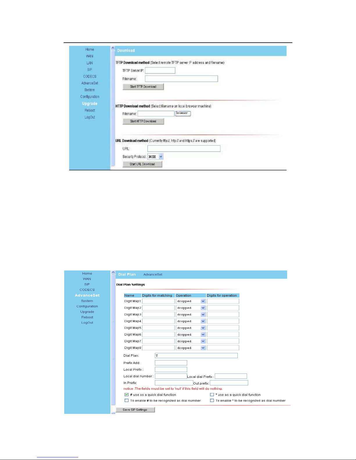
This page provides two options for downloading a new firmware application image to
the device. If you wish to download the new firmware image using TFTP, enter the
filename of the ROM image and enter the IP address of the TFTP server on which this file
resides.
To initiate the TFTP download process, press "Start TFTP Download."
If the ROM image is stored on the same local machine you are using to access the
device’s web pages, you can choose to download the ROM file to the device using an
HTTP post. Enter the filename of the ROM image or press "Browse" to help locate the file.
To initiate the HTTP download process, press "Start HTTP Download."
If the main application is executing at the time, the device will automatically reboot
itself into the downloader mode and begin the download process. If the downloader
application is executing at the time, the download process will begin. The download status
will be displayed when the image download process is complete. Please refer to Section A
“The Downloader Application” for more details on the download process.
Confidential Page 20 3/24/2009
Page 21
E IPP 5000 User’s Manual
HTTP Download method:
When using http to upgrade firmware, it will check firmware version before starting
download process.
In Filename field, press Browsing Button.
Press Start HTTP Download button to start downloading file.
If firmware version doesn't fit in with old version, it won't allow updating.
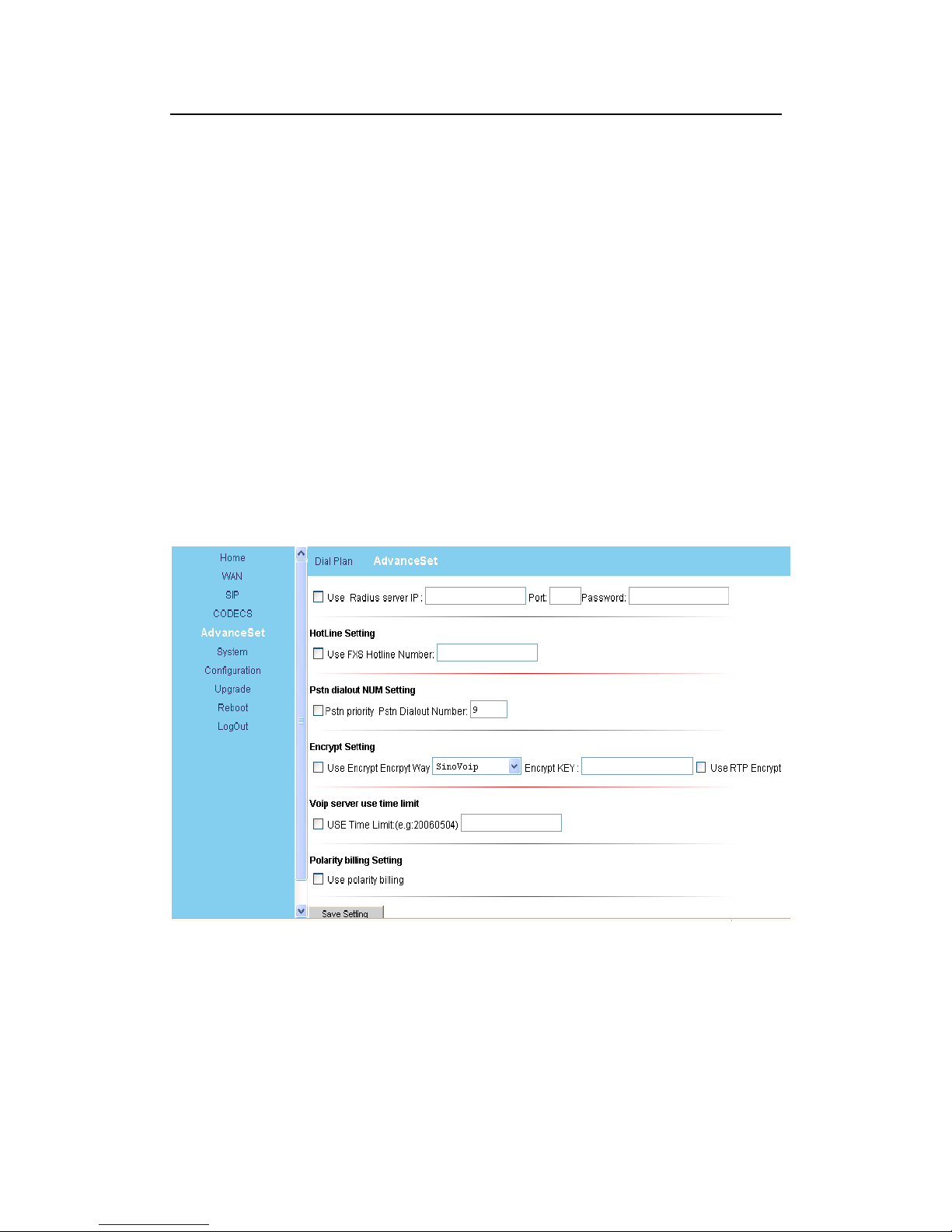
9.7 Advance Setting
Confidential Page 21 3/24/2009
Page 22
E IPP 5000 User’s Manual
z Dial Plan such as 12.1.1
z Digit Map 1: For the No prefixed with 13, 013 will substitute.
eg., when call 1368644111, the send no will be 01368644111
z Digit Map 2: For the No prefixed with 8, 07558 will substitute
But due to the setting of Digit Map 1 & Digit Map 2,this rule
exclude the No prefixed with 86 & 88.
eg., when call 81971911, the send no will be 075581971911
z Digit Map 3: For the No prefixed with 86, 86 will be dropped.
eg., when call 8607552647xxxx, the send no will be 07552647xxxx
z Digit Map 4: For the No prefixed with 88, no change
eg., when call 88011500, the send no will be 88011500
1. Radius billing Setting: Start billing software, Enable “Use Radius server Ip” check
button, enter the IP address of target computer
2. Use FXS Hotline Number: Enable “Use FXS Hotline Number” check button, when
you pick up telephone receiver, the HotLine No will be send automatically immediately.
3. Encrytp setting: association server setting
4. Use Time Limit: Setting the expire date of account No
Polarity billing setting: Enable “Use Polarity billing” check button will Start Polarity billing
Confidential Page 22 3/24/2009
Page 23
E IPP 5000 User’s Manual
function
Note: FXO and PSTN has no used
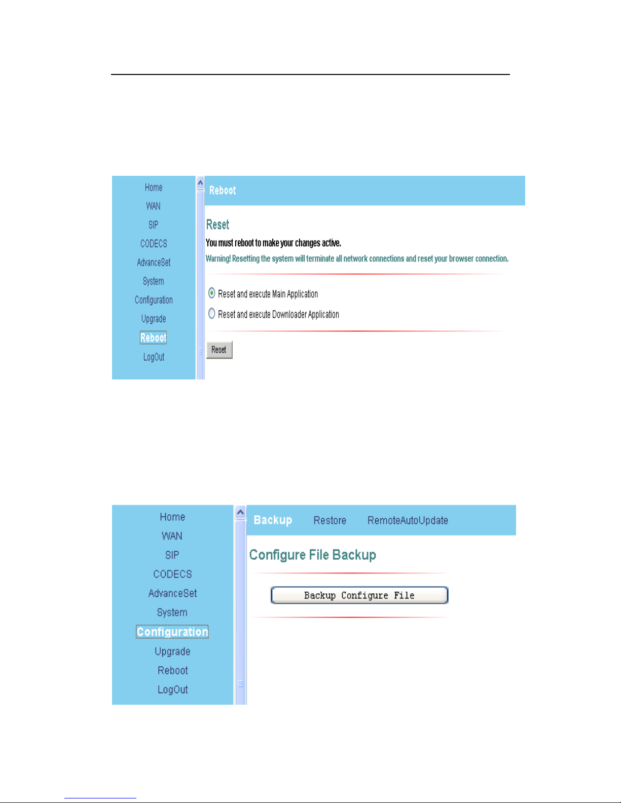
9.8 Reset Setting
This page provides options for resetting the device. Select whether you wish to reset the
device and start executing the main (default) application, or whether you wish to reset the
device and start executing the internal downloader application.
Press "Reset" to reset the device
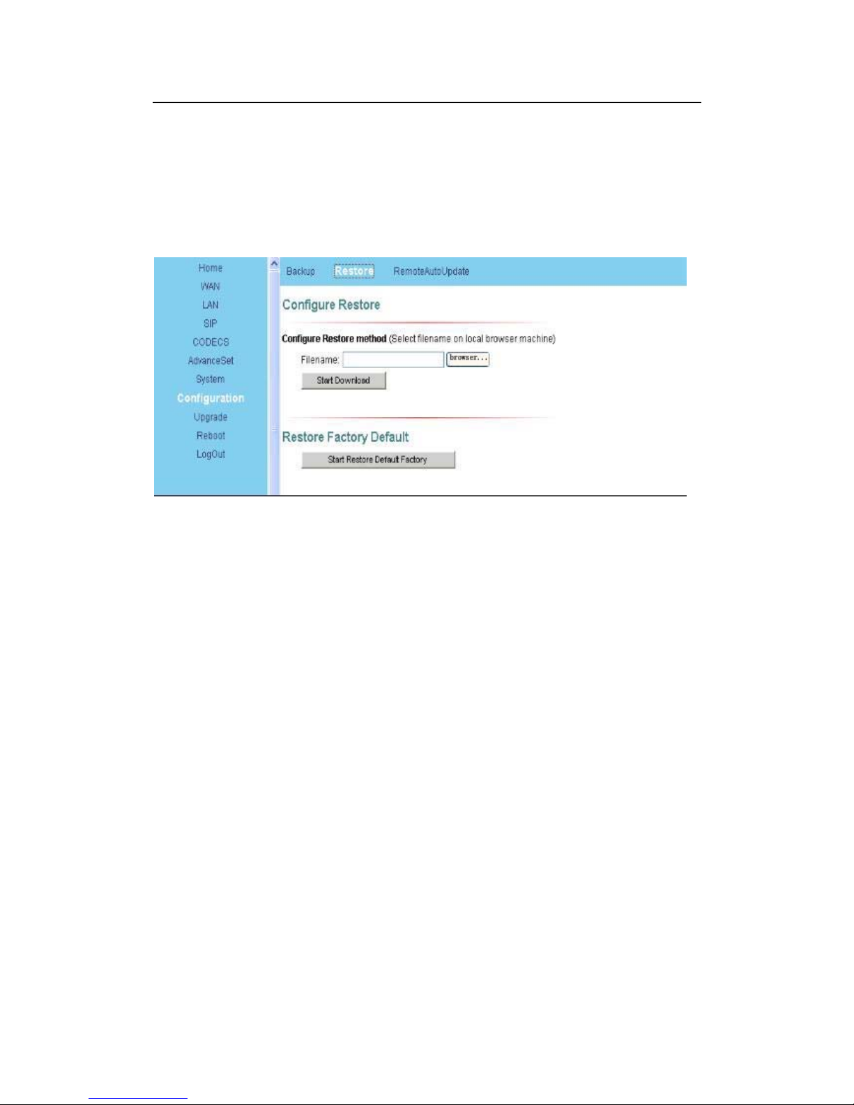
9.9 Config Backup
Backup configuration values of system settings to a file from the device.
Confidential Page 23 3/24/2009
Page 24
E IPP 5000 User’s Manual
Click “Configuration” item on the top menu.
Click “Backup” item on the left menu.
Press Backup Configure File button to save configuration file.
9.10 Config Restore
This page is used to restore configuration values of system settings from a previously
saved configuration file, or default factory values that stored inside the device.
Restore configuration from a file.
Click “Configuration” item on the top menu.
Click “Restore” item on the left menu.
Press Browsing button to select file by backup from local machine.
Press Start Download button to process downloading file.
After downloading file is finished, the web system will redirect to restart device.
Restore default factory values form device.
Click “Configuration” item on the top menu.
Click “Restore” item on the left menu.
Press “Start Restore Default Factory” button.
After restoring default factory, the web system will redirect to restart device.
10 Dial Model
10.1 Direct Dial:
Confidential Page 24 3/24/2009
Page 25

E IPP 5000 User’s Manual
Confidential Page 25 3/24/2009
Dial through VoIP No: Directly pick up telephone, and then dial telephone No
11 Troubleshooting
1. Confirm all cables are connected properly.
2. Check whether there is a proper LAN connection using Ping from your PC command
window.
3. Connect the router to the LAN interface and check whether the router is set properly.
4. Confirm the SIP server settings and the CEALCOMM Encryption Engine Settings.
5. Check the DHCP settings and the LAN Gateway settings.
12 Dial Plan And IVR
12.1.1 Dial Plans
The H.323 and SIP code will allow provisioning (via web browser) of the dial plan. A
dial plan gives the unit a map to determine when a complete number has been entered
and should be passed to the gatekeeper for resolution into an IP address. Dial plans are
expressed using the same syntax as used by MGCP NCS specification.
The formal syntax of the dial plan is described by the following notation:
Digit ::= "0" | "1" | "2" | "3" | "4" | "5" | "6" | "7" | "8" | "9"
Timer ::= "T" | "t"
Letter ::= Digit | Timer | "#" | "*" | "A" | "a" | "B" | "b" | "C" | "c"
| "D" | "d"
Range ::= "X" | "x" -- matches any digit
| "[" Letters "]" -- matches any of the specified letters
Letters::= Subrange | Subrange Letters
Subrange::= Letter -- matches the specified letter
| Digit "-" Digit -- matches any digit between first and last
Position::= Letter | Range
StringElement::= Position -- matches any occurrence of the position
| Position "." -- matches an arbitrary number of occurrences including 0
Page 26

E IPP 5000 User’s Manual
Confidential Page 26 3/24/2009
String ::= StringElement | StringElement String
StringList::= String | String "|" StringList
DialPlan::= String | "(" StringList ")"
A dial plan, according to this syntax, is defined either by a (case insensitive) string or
by a list of strings. Regardless of the above syntax a timer is only allowed if it appears in
the last position in a string (12T3 is not valid). Each string is an alternate numbering
scheme. The unit will process the dial plan by comparing the current dial string against the
dial plan, if the result is under-qualified (partial matches at least one entry) then it will do
nothing further. If the result matches or is over-qualified (no further digits could possibly
produce a match) then send the string to the gatekeeper and clear the dial string.
The Timer T is activated when it is all that is required to produce a match. The period
of timer T is 4 seconds. For example a dial plan of (xxxT|xxxxx) will match immediately if 5
digits are entered, it will also match after a 4 second pause when 3 digits are entered.
D.1 Sample Dial Plans
Simple Dial Plan
This allows dialing of 7 digit numbers (e.g. 5551234) or an operator on 0. Dial plan is
(0T|xxxxxxx)
Non-dialed Line Dial Plan
As soon as handset is lifted the unit contacts the gatekeeper (used for systems where
DTMF detection is done in-call). Dial plan is (x.) i.e. match against 0 (or more) digits. Note:
the dot ‘.’
Complex Dial Plan
Local operator on 0, long distance operator on 00, four digit local extension number
starting with 3,4 or 5, seven digit local numbers are prefixed by an 8, two digit star
services (e.g. 69), ten digit long distance prefixed by 91, and international numbers
starting with 9011+variabl e number of digits.
Dial plan for this is:
(0T|00T|[3-5]xxx|8xxxxxxx|*xx|91xxxxxxxxxx|9011x.T)
12.1.2 IVR
To use IVR, one should pick up the phone, and then dial four consecutive asterisks
(****.) And hang up the phone will stop IVR.
Page 27

E IPP 5000 User’s Manual
Code Status User input
**** Menu Enter choice code.
100# Network status None.
110# DHCP setting 1# to enable
2# to disable
or # back to menu
120# IP address setting Use “*” to instant of “.”, and “#” to end.
Ex: 172*16*230*227#
Or # back to menu.
130# Gateway setting Use “*” to instant of “.”, and “#” to end.
Or # back to menu.
140# Net mask setting Use “*” to instant of “.”, and “#” to end.
Or # back to menu.
Confidential Page 27 3/24/2009
 Loading...