

Page 1
gyM
sy...
Instruction Manual
αlpha-RES1000
Resistivity Controller/Transmitter
68X216807 rev 3 12/04
Technolo
adeEa
Page 2

Page 3

Page 4

Preface
This instruction manual serves to explain the use of the αlpha-RES1000 series Resistivity
controller/transmitter. The manual f unctions in two ways: firs tly as a step by step guide to help the
user operate the instrument. Secondly, it serves as a handy reference guide. This instruction
manual is written to cover as many anticipated applications of the αlpha-RES1000 Resistivity
controller/transmitter. If you have doubts in the use of the instrument, please do not hesitate to
contact the nearest Eutech Instruments’ Authorised Distributor.
The information presented in this manual is subject to chang e without notice as improvements are
made, and does not represent a commitment on part of Eutech Instruments Pte Ltd.
Eutech Instruments cannot accept any responsibility for damage or malfunction of the unit due to
improper use of the instrument.
Copyright ©1999
Rev 3 12/04
All rights reserved.
EUTECH INSTRUMENTS PTE LTD
Blk 55 Ayer Rajah Crescent, #04-16/24, Singapore 139 949.
Tel: (65) 6778 6876; Fax: (65) 6773 0836
E-MAIL: MARKETING@EUTECHINST.COM
WEB SITE: HTTP://WWW.EUTECHINST.COM
;
Page 5

Operating Instructions αlpha-RES1000
TABLE OF CONTENTS
1
INTRODUCTION.................................................................................................1
1.1 DESCRIPTION OF UNIT ....................................................................................1
1.2 APPLICATIONS................................................................................................1
2 ASSEMBLY AND INSTALLATION.....................................................................2
2.1 MEASUREMENT AND CONTROL SYSTEM............................................................2
2.2 UNIT DIMENSIONS ..........................................................................................2
3 ELECTRICAL CONNECTION.............................................................................3
3.1 CONNECTION DIAGRAM...................................................................................3
3.2 BACK PANEL..................................................................................................4
4 OVERVIEW.........................................................................................................5
4.1 KEYPAD AND DISPLAY.....................................................................................5
4.1.1 Keypad ..............................................................................................................5
4.1.2 Display............................................................................................................... 5
4.2 FUNCTION GROUPS ........................................................................................6
4.3 CONTROL CONCEPT .......................................................................................7
5 MEASUREMENT ................................................................................................8
5.1 DISPLAY IN MEASUREMENT MODE ....................................................................8
5.1.1 Check electrode performance ...........................................................................8
5.1.2 Checking set points........................................................................................... 8
5.2 SECURITY CODES...........................................................................................8
5.2.1 How to enter and change parameters in Calibration mode ............................... 8
5.2.2 How to enter and change parameters in Advanced Setup mode...................... 9
6 CALIBRATION MODE......................................................................................10
6.1 RESISTIVITY CALIBRATION.............................................................................10
7 ADVANCED SET-UP MODE............................................................................11
7.1 TEMPERATURE COEFFICIENT SUB-FUNCTION...................................................11
7.1.1 Selecting Pure-water or Linear Temperature Coefficient ................................ 11
7.2 TEMPERATURE CALIBRATION (ATC MODE ONLY)..............................................12
7.2.1 Setting manual temperature compensation..................................................... 12
7.3 CONTROL RELAY A/CONTROL RELAY B (SP1/SP2) SUB-FUNCTION ..................13
7.3.1 Entering the Set point 1 (Set point 2) sub-function.......................................... 13
7.3.2 Selecting the set point values.......................................................................... 13
7.3.3 Choosing High or Low set points..................................................................... 13
7.3.4 Selecting a hysteresis (dead band) value (0.000 to 0.200 m
Ω
) 14
m
7.3.5 Setting an on-delay time lag............................................................................ 14
7.3.6 Setting an off-delay time lag............................................................................ 15
Ω
or 0.00 to 2.00
7.4 CONTROLLER (CNTR) SUB-FUNCTION .............................................................15
7.4.1 Entering the Controller sub-function................................................................ 15
7.4.2 Choosing the controller type (limit or proportional).......................................... 15
7.4.3 Choosing break/make contact relay type ........................................................ 16
7.4.4 Selecting proportional range value Xp............................................................. 16
Page 6

Operating Instructions αlpha-RES1000
7.4.5 Maximum Pulse Length (tPL) or Maximum Frequency (FPF) ......................... 17
7.5 MEASUREMENT RANGE SUB-FUNCTION...........................................................17
7.5.1 Entering the Measuring Range sub-function ................................................... 17
7.5.2 Selecting Measuring Range sub-function........................................................ 17
7.5.3 Measurement Range available in the Controller ............................................. 18
7.5.4 Current Output (rng) sub-function.................................................................... 18
7.5.5 Choosing the output type................................................................................. 18
7.5.6 Selecting Resistivity value at 0(4)mA.............................................................. 18
7.5.7 Selecting Resistivity value at 20mA................................................................. 19
7.6 CONFIGURATION (CONF) SUB-FUNCTION ........................................................19
7.6.1 Entering Configuration sub-function................................................................ 19
7.6.2 Selecting Filter Function and the Alarm or Wash Function ............................. 19
7.6.3 Selecting the alarm time lag (if the relay 3 is set to Alarm) ............................. 20
7.6.4 Selecting steady or pulse contact for the alarm relay (if the relay 3 is set to
Alarm) 20
7.6.5 Wash Contact (if the relay 3 is set to Wash) ................................................... 20
7.6.6 Input Line Resistance Adjust........................................................................... 21
7.6.7 Reverting to factory default settings................................................................ 21
7.7 CALIBRATION (CAL) SUB-FUNCTION ...............................................................21
7.7.1 Entering Calibration mode from Advanced Set-up mode ................................ 21
8 AUTO/MANUAL MODE....................................................................................22
8.1 AUTO MODE (MODE AFTER SWITCH-ON)...........................................................22
8.2 MANUAL MODE.............................................................................................22
9 TECHNICAL SPECIFICATIONS.......................................................................23
10 GENERAL INFORMATION...........................................................................24
10.1 WARRANTY..................................................................................................24
10.2 PACKAGING .................................................................................................24
10.3 RETURN OF GOODS......................................................................................24
10.4 GUIDELINES FOR RETURNING UNIT FOR REPAIR ..............................................24
11 APPENDICES...............................................................................................25
APPENDIX 1 – JUMPER POSITIONS.............................................................................25
APPENDIX 2 – CONDUCTIVITY / RESISTIVITY OF VARIOUS AQUEOUS SOLUTIONS AT 25
O
C26
APPENDIX 3 - SIMPLE EXPLANATION ON THE FUNCTION OF HYSTERESIS ........................26
APPENDIX 4 – PURE WATER CURVE...........................................................................27
Page 7

Operating Instructions αlpha-RES1000
1 Introduction
1.1 Description of Unit
Thank you for purchasing Eutech’s ¼ DIN alpha- 1000 series Resistivity process controllers. This
unit is used for measuring the Resistiv ity of a solution in mega-ohms. You can use this unit to
measure Resistivity with limit control. This c ontroller has many user-friendly and safety features
which include:
• Menu-driven program that simplifies set-up
• Two ranges of Resistivity measurements-software selectable (Section 7.5.3).
• Built-in memory backup to ensure that calibration data and other information are not eras ed
if power supply fails
• Automatic temperature compensation (ATC) with Pt100 or Pt 1000
• Manual temperature compensation with independent setting for calibration and process
temperature
• Temperature coefficient variable between 0.00 to 10.00 % per
compensation curve stored in memory. Reference temperature at 25
• 0 to 1999 second time delay adjustment on all relays – minimise false alarms
• Separately adjustable high and low set point hysteresis (dead bands) prevent chatteri ng of
relays around the set points. Selectable Filter function stabilises rapid measurement changes.
• Three control modes: limit, proportional pulse length or proportional pulse frequency.
• Large dual display LCD for easy reading with clear multiple annunciators, al arm status and
operational message annunciators
• Two switching contacts as set-point triggering relays and an alarm output relay
• Separate alarm relay alerts you when set points have exceeded the limits and if the
Pt100/Pt1000 wires are broken or disconnected during the ATC function
• Hold function freezes output current (0/4...20mA) and releases control relays
• LED indicators signal control activities to monitor controller status from a distance
• Protection against electromagnetic interference - galvan ically isolated 0/4..20mA output
provides safety for data logging and control purposes
1.2 Applications
Use this controller in panel mounted enclosures for applications in Pure water and R.O. Systems.
o
C. Separate pure water
o
C.
1
Page 8
Operating Instructions αlpha-RES1000
(
)
A
y
r
y
r
per
r
p
r
Alarm/Sir
y
p
p
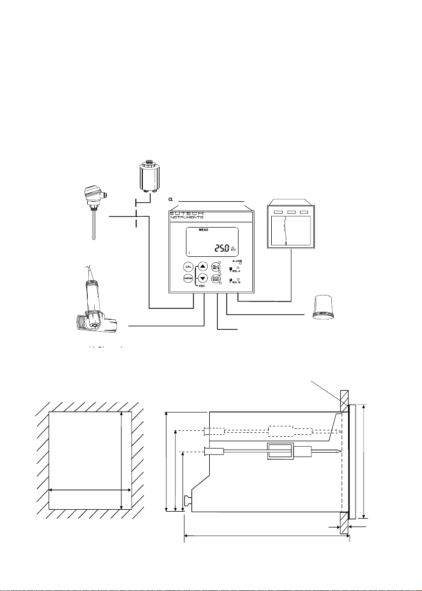
2 Assembly and Installation
2.1 Measurement and Control System
A typical measurement system consists of:
• a αlpha-RES1000 process controller
• a suitable Resistivity electrode with the appropriate Cell constant and integrated temperature
sensor Pt 1000 or Pt 100,
• an immersion, flow or process assembly
• a final control element such as pump or valve and
• a chart recorder
Flow
ssembl
to DosingPumps
Pt100/Pt1000
em
T
atureSenso
P
ocessAssembl
2.2 Unit Dimensions
92 + 0.5
92+ 0.5
l
ha-RES1000 Controlle
92
56
32
Resistivity Controller
lpha RES 1000
α
18.20
Note: The Ta
ChartRecorde
Ω
m
PowerMains
220/110 VAC
Flat Gasket (1mm)
(TobeInsertedByCustomer)
ed CornersHavetoBeOnTo
en
S
stem
96
Mounting Cut-Out
max. 175
max. 45
The field-tested control panel housing is 96 x 96 mm; with protection class IP 54 (front).
2
Page 9
Operating Instructions αlpha-RES1000
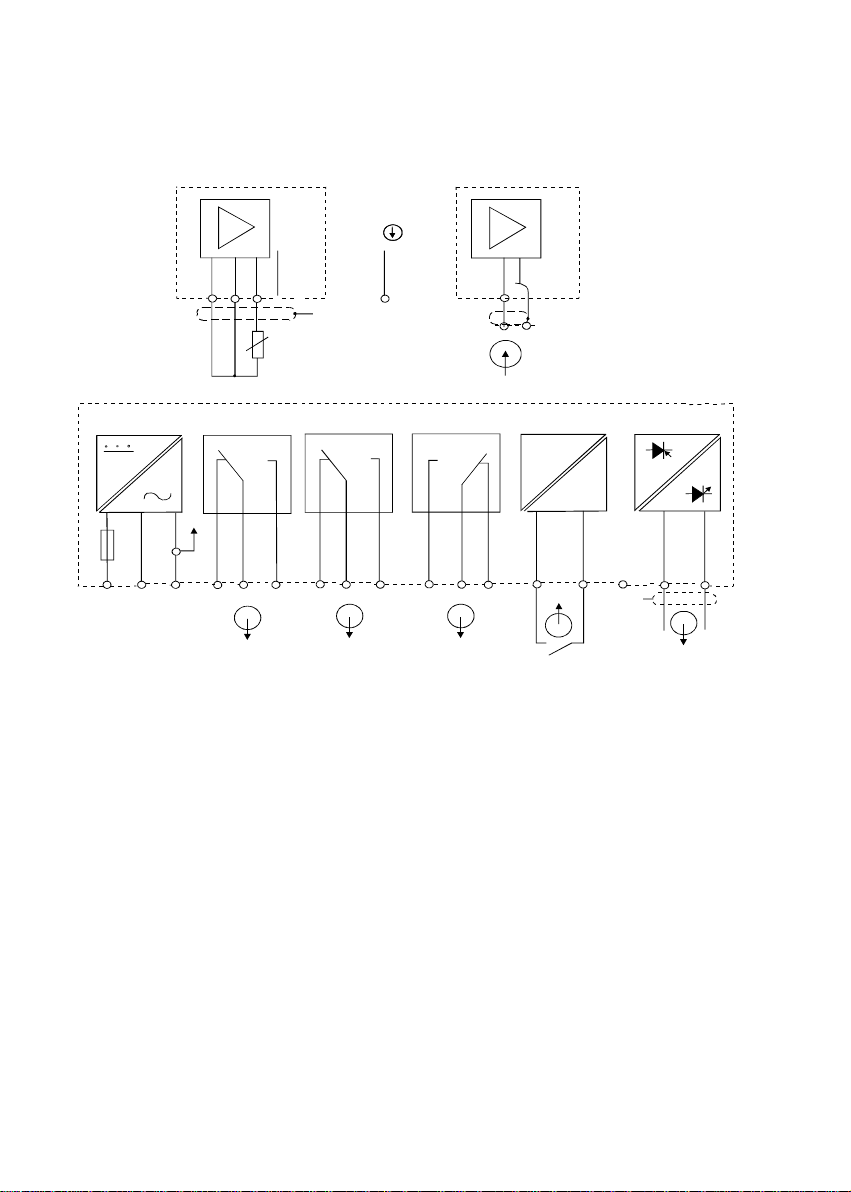
3 Electrical Connection
3.1 Connection Diagram
RES
S/
V
S/
O
P o w e r M a i n s
1
1 8 1 9 2 0
Pt 1000/100
2
3 6
P EA C : N L
Alarm
10
21 22
Signal Input
11
12 13
Resistivity
14
PE/S
e l a y A
R
5
4
* ) i n d i c a t e d c o ntact positions are for currentless conditions
Relay B
7 8 9
NC
PE/S
Signal O u t p u t Hold Input
RES
mA
+
-
1 6
15
15
1 7
3
Page 10
Operating Instructions αlpha-RES1000
/
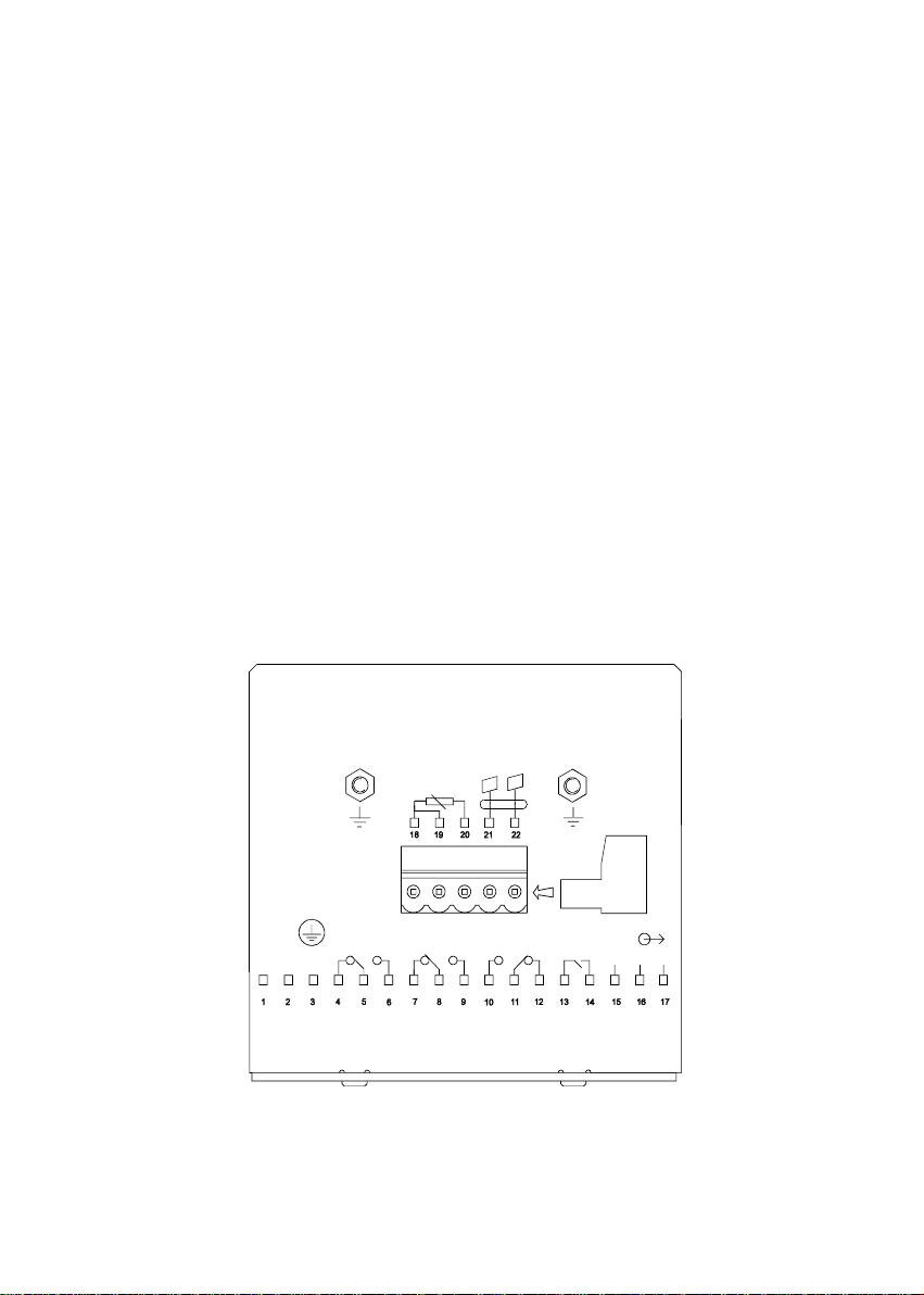
3.2 Back Panel
The back panel consists of two connectors. The first connector is the 17-way PCB edge connector and
the other is the 5-way connector.
Connection for the 17-way screw terminals (from left to right):
1. AC mains live wire 10. Alarm/Wash relay resting position (NO)
2. AC mains neutral wire 11. Alarm/Wash relay common
3. AC mains protective earth wire 12. Alarm/Wash relay working position (NC)
4. Relay 1 relay resting position (NC) 13. Hold function switch terminal 1
5. Relay 1 relay common 14. Hold function switch terminal 2
6. Relay 1 relay working position (NO) 15. No connection
7. Relay 2 relay resting position (NC) 16. 0/4 - 20 mA for -ve connection
8. Relay 2 relay common 17. 0/4 - 20 mA for +ve connection
9. Relay 2 relay working position (NO)
Connections for the 5-way screw terminals:
18. Pt1000/Pt100 lead 1 terminal (red)
19. Pt1000/Pt100 sense lead terminal (short 18 & 19 if using a two-wire system)
20. Pt1000/Pt100 lead 2 terminal (green)
21. Resistivity lead 1 (black)
22. Resistivity lead 2 (white)
*cable wire colours stated above are applicable to EC-CS10 series. For other electrodes, please check
electrode specifications.
cell
ALARM
J2
+
HOLD
-
NC
FUSE 250VAC
100 mA
(F)
LNPE
RELAY1
Pt100
Pt1000
RELAY2
IMPORTANT: The Alarm relay functions as an “Active Low” device i.e. it switches OFF under
Alarm condition. Therefore the Alarm display device should be connected to the ‘NC’ contacts of
the relay. If the relay is configured as “wash”, then it works in the ‘Active High’ mode. Therefore
the wash pump has to be connected across its “NO” contacts.
4
Page 11
Operating Instructions αlpha-RES1000
4 Overview
4.1 Keypad and Display
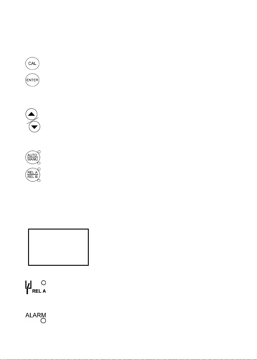
4.1.1 Keypad
Perform rapid calibration
•
•
Allows entry to Set up mode
• Select individual functions within the function group of Set up mode
• Store input data in the Set up mode
• Start calibration in the calibration mode
•
Select various function groups in the Set up mode.
• Set parameters and numerical values in sub functions of Set up mode
If pressed continuously, the setting speed increases
• Control the relays in the MANUAL function
• Return to the Measurement mode when both keys are pressed together
•
Switch between AUTO and MANUAL relay operation using a code
•
Display set-point values for the switch contacts in AUTO operation mode
• Switch between RELAY A and RELAY B in MANUAL relay operation mode
4.1.2 Display
The LCD display features two numerical displays that show s tatus messages and measured v alues for
easy, quick reference. The display provides short-text information for setting parameters and
configuration.
HOLD SETUP MEAS CAL
READY
-8.8.8.8
8
Display for RELAY A/B. Green LED indicates measured value within limit while
•
RED LED indicates measured value outside limit.
• Alarm display if limit value overshoot or the ATC connection is broken.
• HOLD: Relay position and current output are frozen
• SETUP: Set-up mode of function groups
• MEAS: Measurement mode
mΩ
• CAL: Calibration mode of Resistivity
• READY: Comes on after a successful calibration
o
C
• ATC: Comes on in the ATC mode. Disappears in the
Manual temperature Compensation mode. “ ATC” flashes
if the temperature probe is faulty in its ATC mode
• Range No.: Indicates the measurement range selected
5
Page 12

Operating Instructions αlpha-RES1000
4.2 Function Groups
The main function and sub-function groups are organised in a matrix format for configuration and
selection of parameters. The main function groups are:
1) Temperature Coefficient settings (tC)
2) Temperature Measurement / compensation settings (SEt
3) Control relay 1 configuration (SP1)
4) Control relay 2 configuration (SP2)
5) Control type (Cntr)
6) Current output (rng)
7) Configuration (ConF)
8) Calibration (CAL rES)
HOLD
SETUP
HOLD
SETUP
HOLD
SETUP
o
C)
HOLD
SETUP
SETUP
SEt
o
C
HOLD
tc
SETUPHOLD
HOLD SETUP
SP1
rng
HOLD
SP2
SETUP
Cntr
rES
Set-up parameters can be viewed or changed by ente ring a security code. See Section 5 .2 for security
code information.
4.2.1 How to view operating parameters without access to change them:
000
S.Cd
c) Press ∆ or ∇ keys to scroll through sub-functions.
d) Press ENTER key at a particular sub-function to view in detail.
e) Press ENTER key to return to sub-function menu.
f) Press ∆ and ∇ keys simultaneously (Escape key) at any time to return to Measurement mode.
Note: To simplify operations, the controller will not display parameters that are not relevant to a
particular sub-function.
a) Press ENTER key. Display will prompt to enter security code
(S.Cd). Leave security code at “000” (do not enter a security
code).
b) Press ENTER key again. This allows for viewing (not change)
any sub-functions’ settings.
6
Page 13

Operating Instructions αlpha-RES1000
4.3 Control Concept
The main function and sub-function groups are organised in a matrix fo rmat as shown below. These
functions can be accessed via the front keypad for configuration and selection of parameters.
Controller offers three levels of password protection: (1 ) for viewing all S ETUP Configurat ion with out the
facility to make changes; (2) for direct access to calibration function; and (3) for setting or editing
specific controller parameters or functions in SETUP mode.
Note: Passwords are not user-defined and ar e set by factory. Please keep passwords c onfidential to
avoid unauthorised tampering of the system.
7
Page 14

Operating Instructions αlpha-RES1000
5 Measurement
5.1 Display in Measurement mode
When controller is powered on, it au tomatical ly enters into the Measure ment mod e after l arge dual LCD
briefly displays all segments.
The upper display shows the meas ured Resis tivity value, whil e lower dis play shows tempe rature value.
Annunciators at right side of the display indic ate mΩ and
or left side of the display shows current s tatus of controller, e.g. “HOLD”, “SETUP”, “MEAS”, “CAL”,
“READY”, etc.
5.1.1 Check electrode performance
To read current electrode condition without changing them:
1) Press the CAL key followed by the ENTER key without adjusting the security code (leave code at
“000”). The upper display shows the last cell constan t as a percenta ge with the l ower displ ay shows
“CEL”. Press ENTER key and the next upper display shows the last calibration factor.
Note: If security code is changed to a va lue other than “000”, pressing ENTER key will return to
Measurement mode, without displaying electrode infor mation.
2) Press ENTER key a second time to return to Measurement mode.
5.1.2 Checking set points
To read current set point values without changing them:
Press RELAY Selection (Rel A / Rel B) key. Upper display shows set point for Relay A; lower display
shows “SP1”.
After two seconds upper display shows set-point value for Relay B; lower display shows “SP2”.
After an additional two seconds, controller returns to Measurement mode.
5.2 Security Codes
Two levels of security protection with separate sec urity codes are provi ded. First level allows entry into
the Calibration mode: security code = 11; second allows entry into SETUP mode: security code = 22.
Security codes protect controller from unauthoris ed tampering. Parameters cannot be ch anged unless
the security code is entered.
5.2.1 How to enter and change parameters in Calibration mode
1) Press CAL key. Upper display shows “000” and lower display
shows “C.Cd” to prompt for Calibration security code.
2) Press ∆ or ∇ ke ys to scroll upper display to Calibration security
code “11”.
3) Press ENTER key. Display shows “CAL RES”.
4) Press ENTER again to begin calibration. Refer to Section 6 for full details on calibration.
5) Press ∆ and ∇ keys simultaneously (escape) to return to Measurement mode.
o
C. Similarly annunciators or icons at the top
1 1
C.Cd
8
Page 15

Operating Instructions αlpha-RES1000
NOTE: To view (not change) electrode condition, p ush ENTER key when the security code reads
“000”.
5.2.1.1 Clearing Calibration security code from display
The calibration security code automatically res ets from “11” to “000” after returning to Measurement
mode.
5.2.2 How to enter and change parameters in Advanced Setup mode
1) Press ENTER key once. Upper display shows “000” and lower display shows “S.Cd” to prompt for
Advanced Setup security code.
2) Press ∆ or ∇ keys to scroll display to Setup sec urity code “22”. NOTE: Pressing ENTER key at a
value other than “22” causes the controller to revert to Measurement mode.
3) Press ENTER key.
4) Upper display reads “tc”. You are now in the Adv anced Setup mode. See Section 7 for compl ete
instructions. To return to Measurement mode, press ∆ and ∇ keys simultaneously (escape).
NOTE: If to view (not change) set up parameters , p us h ENTER k ey when s ecurity c ode rea ds “000”.
5.2.2.1 Clearing Advanced Setup security code from display
Having entered the security code and returned to the Measurement mode, security code “22” still
appears on display whenever ENTER k ey is press ed. To conc eal the s ec urity code, it mus t be m anual ly
reset. To clear Advanced Setup security code from display:
1) Press ENTER key in Measurement mode.
2) Set to any security code (not 11 or 22) and complete by pressing ENTER.
NOTE: When you enter the Calibration mode with code “11” or Advanced Setup mo de with security
code “22”, unit automatically enters into HOLD mode until you return back to Measurement mode.
The HOLD annunciator is displayed at the upper left of the display. While on HOLD, current
(0/4..20mA) output is frozen and set point relays are deactivated.
9
Page 16

Operating Instructions αlpha-RES1000
6 Calibration Mode
Calibration mode can be accessed directly from Measurem ent mode by press ing CAL key and ent ering
the Calibration security code; or from the Advanced Setup mode.
6.1 Resistivity Calibration
Calibration is always carried out in the specific range selected. The Resistiv ity Controller allows a onepoint calibration.
1) Enter Calibration mode. While in Measurement mode,
Note: The acceptable calibration window is ±40% of the displayed (default) value. If the
displayed is 10.00 mΩ standard, the values to which it can be adj usted is 6.00 to 14.00 mΩ. If
there is a calibration error, the controller displays “ERR” annunciator. To recalibrate repeat step
3. To exit from calibration, push both ∆ and ∇ keys (escape) to resume to Measurement mode.
5) Press ENTER key. If you entered calibration mode using CAL key, controller will return to
Measurement mode. If you entered calibra tion mode from Advanced Set-up mode, controller will
return to sub-function menu.
Note: When calibrating with manual temper ature compensation, controller a utomatically changes from
preset process temperature to calibrati on temperature. After leaving the Calibration mode, controller
switches back to process temperat ure (f or sett in g cal ibratio n tem per ature and pr oc ess temp erature, see
section 7.2).
HOLD SETUP
1
HOLD CAL
100.0
1
HOLD CAL
CEL
18.20
1
HOLD CAL
25.0
1.01
FCt
1
CAL
rES
mΩ
oC
ATC
press CAL key and scroll to Calibration c ode “11”. Press
ENTER key. The upper display reads “CAL” and lower
display, “rES”.
2) Press the ENTER key. The controller displays its last set
Cell Constant (k) of the cell as a percentage of the
theoretical value. Using the up a nd down key, the v alue can
be set to anywhere from 80 to 120%. Press th e ENTER key
again to carry out calibration.
%
3) Immerse the Conductivity cell in a suitable standard
solution, whose value is within the measurement range
selected in the controller. Agitate the Cell in the solut ion to
remove any trapped air-bubbles. Note: The calibration
standard should have a value that is between 2 0% to 100%
of the range selected. For example, if the range in the
controller is selected to be 19.99 mΩ (range 1), then the
calibration standard value should be 4.00 mΩ to 19.99 mΩ.
4) Once the reading has stabilized, use the ∆ or ∇ keys to
adjust the measured value to that of the standard solution.
Press the ENTER key to accept the value and the co ntroller
displays the revised condition of the probe The lower d isplay
shows the factor “FCt” while the upper display shows the
ratio of ideal to adjusted calibration value.
10
Page 17

Operating Instructions αlpha-RES1000
7 Advanced Set-Up Mode
7.1 Temperature Coefficient sub-function
This sub-function allows you to select correct temperature coefficient for optimum operations. For
applications in pure water or ultra-pu re water industries , select “ Pur” temperature co efficient opti on. For
all other applications, select “Lin” temperatur e coefficient. Controller allows further inp ut of temperature
coefficient values, independently for process and for calibrating solutions. Default is “Pur”.
HOLD SETUP
tc
7.1.1 Selecting Pure-water or Linear Temperature Coefficient
1) Enter Advanced set-up mode. Push ENTER key and scroll to
Advanced Set-up security code “22”. Push ENTER key. Controller
displays “tC”. Press ENTER key again. Controller display s “Pur” in
upper display and “tC” in lower display. Default is “Pur”.
2) Press ∆ or ∇ keys to select between “Pur” and “Lin” temperature
coefficients. If “Lin” tC is to be selected, press ENTER key when
controller displays “Lin”.
3) If “Lin” is selected, upper display shows “2.10%”, while lower
display show “P.tC”. This option allows input of Process
Temperature coefficient, from 0 to 10%. Default is 2.10%. Use ∆
or ∇ keys to enter required temperature coefficient value.
4) Press ENTER key. Next, enter the calibration solution
temperature coefficient value, “C.tC”, from 0 to 10%. Default is
2.10%.
5) Press ∆ or ∇ keys to input desired calibration solution
temperature coefficient.
6) Press ENTER key to accept.
7) Continue with additional Advance setup procedures or return to
Measurement mode by pressing ∆ and ∇ keys (escape)
simultaneously.
HOLD SETUP
HOLD SETUP
Lin
tC
Pur
tC
HOLD SETUP
2.10
P.tC
%
ATC
HOLD SETUP
%
2.10
ATC
C.tC
HOLD SETUP
HOLD SETUP
HOLD SETUP
HOLD SETUP
tc
Lin
tC
2.10 %
P.tC ATC
2.10 %
C.tC ATC
11
Page 18

Operating Instructions αlpha-RES1000
7.2 Temperature calibration (ATC mode only)
1) Enter Advanced Set-up mode. Push the ENTER key and scroll to
Advanced Set-up security code “22”. Push the ENTER key again.
2) Press the ∆ or ∇ keys to scroll through the sub-menus until the
display shows “Set
o
C”. Press the ENTER key.
3) Press the ∆ or ∇ keys to scroll until the upper display shows “ATC”,
and the lower display shows “on”. Default setting is “ATC on”.
4) Press the ENTER key. In this mode, the ATC probe can be
calibrated. The upper display indica tes the current te mperature offset.
The current measured temperature is shown in the lower display.
5) Compare the current measured temperature on the controller display
to a thermometer known to be accurate. Note down the correct
temperature value.
6) Press the ∆ or ∇ keys to scroll the lower display to match the
correct value. The upper display will now show the offset value. You
o
can offset temperature up to ± 10
C.
7) Press the ENTER key to confirm your selection.
8) Continue with additional Advanced Set-up procedures, or return to
the Measurement mode by pressing the ∆ and ∇ keys (escape)
simultaneously.
HOLD SETUP
HOLD SETUP
HOLD SETUP
Set
o
C
on
Atc
0.0
25.0
o
C
ATC
7.2.1 Setting manual temperature compensation
HOLD SETUP
oFF
Atc
HOLD SETUP
25.0
P.C
HOLD SETUP
25.0
C.C
temperature and lower display shows “C.
6) Press ∆ or ∇ keys to adjust calibration temperature value, –9.9 to 125
Note: This parameter is unavailable if ATC is selected.
For manual temperature compensation, two different temperatures:
process and calibration can be inp ut independently. Example: setting a
calibration temperature of 25
buffer solutions at 25
o
C, even if process temperature is different.
o
C lets you calibrate using standard
1) Enter Advanced set-up mode. Push ENTER key and scroll to
Advanced Set-up security code “22”. Push ENTER key and
Press ∆ or ∇ keys to scroll till display shows “Set oC”. Press
ENTER.
2) Pressing the ∆ or ∇ keys keys toggle between ATC ‘on’ or ‘off ’
(default setting is ATC on). Select “ATC off”.
3) Press ENTER key. Upper display shows current process
temperature and lower display shows “P.
o
C” to indicate process
temperature.
4) Press ∆ or ∇ keys to adjust process temperatur e value from –
9.9 to 125
5) Press ENTER key. Upper display shows current calibration
o
C.
o
C” to indicate calibration temperature.
o
C. Press ENTER key.
12
Page 19

Operating Instructions αlpha-RES1000
7) Continue with additional Advanced Set-up procedures, or return to Measurement mode by
pressing ∆ and ∇ keys (escape) simultaneously.
7.3 Control Relay A/Control Relay B (SP1/SP2) sub-function
SP1 option sets operating parameters for Rel ay A; and SP2 for relay B. Sinc e these groups have the
same set-up parameters, they are described together.
HOLD SETUP HOLD SETUP HOLD SETUP HOLD SETUP HOLD SETUP HOLD SETUP
SP 1
1.00
SP 1
Lo
SP 1
0.20
HYS
On.d
0
0
Of.d
7.3.1 Entering the Set point 1 (Set point 2) sub-function
1) Enter Advanced Set-up mode. Push the ENTER key and
scroll to Advanced Set-up security code “22”. Push the
ENTER key again.
2) Press the ∆ or ∇ keys to scroll until the upper display
shows SP1 (SP2).
7.3.2 Selecting the set point values
This lets you choose the value that will ca use your controller to
activate (Default: SP1 = 1.00 mΩ; SP2 = 19.00 mΩ).
1) Follow directions in 7.3.1 to enter Control Relay mode. If
you are in this mode, skip to step 2.
2) Press the ENTER key. The upper display shows the
current set point value and the lower display shows SP1
(SP2).
3) Press the ∆ or ∇ keys to select your value for Set point 1
(Set point 2). Your controller will activate at the v alue you
select.
4) Press the ENTER key to confirm your selection.
5) Proceed to 7.3.3, or return to Measurement mode by pressing the ∆ and ∇ keys simultaneously
(escape).
HOLD SETUP
HOLD SETUP
HOLD SETUP
SP 1
1.00
SP 1
Lo
SP 1
mΩ
7.3.3 Choosing High or Low set points
When ‘Lo’ is selected, the control relay is activated wh en the value is lower than SP1 (SP2). When ‘Hi’
is selected, the control relay is activ ated when the value is higher t han the set point (SP1/SP2). Usin g
both SP1 and SP2, you can select lo/lo, lo/hi, hi/lo, or hi/hi set points (Default: SP1 = Lo; SP2 = Hi).
1) Follow directions in 7.3.1 to enter Control Relay mode.
2) Press the ENTER key until the upper display shows Lo or Hi ( for low or high set point) and the
lower display shows SP1 (SP2).
3) Press ∆ or ∇ keys to select low (lo) or high (hi) set point for SP1 (SP2). Press ENTER key.
13
Page 20

Operating Instructions αlpha-RES1000
4) Proceed to 7.3.4, or return Measurement mode by pressing ∆ and ∇ keys simultaneously
(escape).
7.3.4 Selecting a hysteresis (dead band) value (0.000 to 0.200 mΩ or 0.00 to 2.00 mΩ)
Hysteresis prevents rapid contact switching if the value is fluctuating near th e set point. It does this by
overshooting the set point value to a specifie d hysteresis value (default is 0.20 m Ω). You can set the
hysteresis value from 0.000 to 0.200 mΩ or 0.00 to 2.00 mΩ.
Example: Set point 1 (Lo) is at 1.00 mΩ and hysteresis limit value is at 0.20 mΩ. If measured value
undershoots low set point of 1.00 mΩ, relay activates, whic h in turn activates an external device such
as a pump or valve. Actions of the external device will c ause the value to rise above 1.00 mΩ. When
the value has increased to 1.20 mΩ, relay, and hence the pump will switch off.
HOLD SETUP
20
HYS
other.
4) Press ENTER key to confirm your selection.
5) Proceed to 7.3.5, or return to Measurement mode by pressing the ∆ and ∇ keys simultaneously
(escape).
NOTE: Please refer to Appendix 4 for a graphical representation of the Hysteresis
1) Follow directions in 7.3.1 to enter Control Relay mode.
2) Push the ENTER key. The upper display shows the hysteresis
µS
(dead band) value and the lower display shows “HYS”.
3) Press ∆ or ∇ keys to enter hysteresis value for Set point 1 (Se t
point 2). Controller will activate at the value selected. Note: All
settings for SP1 and SP2 are completely independent of each
.
7.3.5 Setting an on-delay time lag
You can set as time delay for each relay, which st ops the relay from switching on the moment the set
point is exceeded. This controller lets you set a 0 to 1999 seconds time delay before the relay activates.
HOLD SETUP
0
On.d
4) Press the ENTER key to confirm your selection.
5) Proceed to 7.3.6, or return to Measurement mode by pressing the ∆ and ∇ keys simultaneously
(escape).
1) Follow directions in 7.3.1 to enter Control Relay mode.
2) Push the ENTER key. The upper display shows “0” time and
the lower display shows “On.d”.
3) Press the ∆ or ∇ keys to enter on-delay time for Set point 1
(Set point 2). The controller will delay activation for the number of
seconds (0 to 1999) you select.
14
Page 21

Operating Instructions αlpha-RES1000
7.3.6 Setting an off-delay time lag
You can set as time delay for each relay, whic h stops the relay fr om swi tching off the mom ent the va lue
reached the set point and hysteres is. This contr oller l ets you set a 0 to 199 9 seconds time delay before
your relay deactivates.
1) Follow directions in 7.3.1 to enter Control Relay mode.
2) Push the ENTER key. The upper display shows “0” time and the
lower display shows “OF.d”.
3) Press the ∆ or ∇ keys to enter on-delay time for Set point 1 (Set
point 2). Controller will delay activation f or the number of seconds
(0 to 1999) selected (Default off delay is 0).
4) Press the ENTER key to confirm your selection.
5) Continue with Advanced Set-up mode procedures, or return to Measurement mode by pressing
the ∆ and ∇ keys simultaneously (escape).
HOLD SETUP
0
OF.d
7.4 Controller (Cntr) sub-function
You can set the controller’s parameters in this sub-function.
7.4.1 Entering the Controller sub-function
1) Enter Advanced Set-up mode. Push ENTER key and scroll to Advanced set-up security c ode
“22”. Push ENTER key.
2) Press ∆ or ∇ keys to scroll until upper display shows “Cntr”.
HOLD SETUP
Cntr
L.Ct
tYP
HOLD SETUP
oFF
tYP
HOLD SETUP
PLC
tYP
HOLD SETUP
PFC
tYP
7.4.2 Choosing the controller type (limit or proportional)
This mode lets you choose your controller type: limit control, pulse length proportional control, puls e
frequency proportional control, or control off.
- Use limit control with pumps or values for fast response.
- Use pulse frequency proportional control to operate your pumps smoothly.
- Use pulse length proportional control for precise control of proportioning valves.
- Use control off to operate controller as a monitor only or to keep relays from switching.
15
Page 22

Operating Instructions αlpha-RES1000
1) Follow directions in 7.4.1 to enter Controller mode.
2) Press the ENTER key. The upper display shows the current controller type and the lower display
shows “tYP”.
3) Press the ∆ and ∇ keys to select your controller type.
- L.Ct = limit value pickup (on/off control).
- oFF = controller off.
- PLC = pulse length control.
- PFC = pulse frequency control.
4) Press the ENTER key to confirm your selection.
5) Proceed to 7.4.3 step 3, or return to Measurement mode by pressing the ∆ and ∇ keys
simultaneously (escape).
7.4.3 Choosing break/make contact relay type
Note: If the controller type “oFF” is set, the parameters listed in 7.4.4 and 7.4.5 are blanked out.
This mode lets you determine the r elay-state under No n-Alarm condition – d EEN (de-energised) or EN
(energised).
HOLD SETUP
dEEn
rEL
HOLD SETUP
En
rEL
7.4.4 Selecting proportional range value Xp
Note: If the controller type “oFF” or “L.Ct” is set, the parameters listed in 7.4.4 and 7.4.5 are blanked out.
This mode lets you set a band as a percentage of its full scale val ue. You can selec t this range from 10
to 200%, and the lower display shows “PrP”.
HOLD SETUP
100
PrP
4) Press the ENTER key to confirm your selection.
5) Proceed to 7.4.5 step 3, or return to Measurement mode by pressing the ∆ and ∇ keys
simultaneously (escape).
1) Follow directions in 7.4.1 to enter Controller mode.
2) Press the ENTER key. Scroll until the lower display shows “rEL”
and the upper display shows the current sel ection (de-energised
= dEEN or energised = EN).
3) Press the ∆ or ∇ keys to choose de-energised or energised
relay state.
4) Press the ENTER key to confirm your selection.
5) Continue with Advanced Set-up mode procedures, or return to
Measurement mode by pressing the ∆ and ∇ keys
simultaneously (escape).
1) Follow directions in 7.4.1 to enter Controller mode.
2) Press the ENTER key. Scroll until the upper display s hows the
proportional range (a number from 10 to 200%) , and the lower
display shows “PrP”.
3) Press the ∆ and ∇ keys to choose the proportional r ange v alue
Xp.
16
Page 23
Operating Instructions αlpha-RES1000
g
7.4.5 Maximum Pulse Length (tPL) or Maximum Frequency (FPF)
Note: If the controller type “oFF” or “L.Ct” is set, the parameters listed in 7.4.4 and 7.4.5 are blanked out.
This mode lets you set the maximum pulse length or the maximum frequency at which the relay will
operate.
HOLD SETUP
10.0
t.PL
HOLD SETUP
60
F.PF
4) Press the ENTER key to confirm your selection and to return to Adva nced Set-up mo de, or return
to Measurement mode by pressing the ∆ and ∇ keys simultaneously (escape).
1) Follow directions in 7.4.1 to enter Controller mode.
2) Press the ENTER key. Scroll until the lower display shows “t.PL”
or “F.PF”.
- In PLC (pulse length) mode: The lower display shows “t.PL” to
indicate pulse length. The upper display shows your current
pulse length. You can select any value from 0.5 to 20 seconds.
- In PFC (pulse frequency) mode: The lower display shows F.PF to
indicate pulse frequency. The upper display shows your current
maximum pulse rate. You can sele ct any value from 60 to 120
pulses per minute. When the measured value exceeds the
Proportional Band in 7.4.4, the con troller will pulse the relay at
this rate.
3) Press the ∆ and ∇ keys to choose the period duration or
maximum frequency, depending on your mode.
7.5 Measurement Range sub-function
In this sub-function, appropriate range is selected with the appropriate cell constant.
7.5.1 Entering the Measuring Range sub-function
1) Enter Advanced Set-up mode. Push ENTER key and scroll to Advanced Set-up security code
“22”. Push ENTER key.
2) Press ∆ or ∇ keys to scroll until upper display shows “rng”.
HOLD SETUP
HOLD SETUP
1
rn
20.00
0.01
7.5.2 Selecting Measuring Range sub-function
1) Follow directions in 7.5.1 to enter Controller mode and press
ENTER key.
2) Press ∆ or ∇ keys to select correct rang e. (Please refer to 7.5.3
for full list of measurement ranges). Note the upper display shows
maximum measurement range, while lower display shows Cell
constant. Lower left-corner of LCD displays the number
mΩ
corresponding to the respective range.
3) Press ENTER key to confirm.
4) Proceed to 7.5.4 to set current output or return to M easurement
mode by pressing ∆ and ∇ keys simultaneously (escape).
17
Page 24

Operating Instructions αlpha-RES1000
7.5.3 Measurement Range available in the Controller
Range No. Range Resolution Default cell K
1
2
0.000 – 19.99 mΩ 0.01 mΩ
0.00 – 1.999 mΩ 0.001 mΩ
0.01
0.1
7.5.4 Current Output (rng) sub-function
This sub-function lets you set the transmitter current output range of this unit. The differen ce between
the upper and lower range has to be a minimum of 20% of Full Scale, anywhere on the scale.
1) Follow directions in 7.5.2 to enter Controller mode.
HOLD SETUP
2) Press ENTER key. Please refer to 7.5.5 for current output
sub-function.
7.5.5 Choosing the output type
This parameter lets you choose between 0-20 mA or 4-20 mA
output.
1) Follow directions in 7.5.4 to enter Current Output mode.
2) Scroll with the ENTER key until the upper display shows the
output type (0-20 or 4-20), and the lower display shows “out”.
3) Press the ∆ or ∇ keys to select your output type: 0-20 or 4-20
mA.
4) Press ENTER key to confirm your selection.
5) Proceed to 7.5.6, or return to Measurement mode by pres sing
the ∆ and ∇ keys simultaneously (escape).
1
HOLD SETUP
1
HOLD SETUP
1
4-20
out
0.00 mΩ
r.4
20.00 mΩ
r.20
7.5.6 Selecting Resistivity value at 0(4)mA
This parameter selects the resistivity value at which transmitter output will be 0(4) mA. Follow
directions in 7.5.4 to enter Current Output mode.
1) Press ENTER key until upper display shows a resistivity value and lower display shows “r.0(4)”.
Ω
2) Press ∆ or ∇ keys to select required resistivity value to be equivalent to 0(4) (Default is 0.00 m
Please note that difference between value at 4mA and 20mA mus t be at least 20% of F.S. Press
ENTER key.
3) Press ENTER key to return to Advanced Set-up mode, or return to Measurement mode by
pressing ∆ and ∇ keys simultaneously (escape).
).
18
Page 25

Operating Instructions αlpha-RES1000
7.5.7 Selecting Resistivity value at 20mA
This parameter selects the resistivity value at which transmitter output will be 20mA.
4) Follow directions in 7.5.4 to enter Current Output mode.
5) Press the ENTER key until upper display shows a resistivity value and lower display shows “r.20”.
6) Press the ∆ or ∇ keys to select the required resistivity value to be equivalent to 20 mA (Default is
20.00 mΩ).Note that difference between the value at 4mA and 20mA must be at least 20% of F.S.
7) Press the ENTER key to confirm your selection.
8) Press the ENTER key to return to Advanced Set-up mode, or return to Measurement mode by
pressing the ∆ and ∇ keys simultaneously (escape).
7.6 Configuration (ConF) sub-function
This group of parameters lets you configure the controller to suit your requirements.
7.6.1 Entering Configuration sub-function
1) Enter Advanced Set-up mode. Push ENTER key and scroll to Advanced Set-up security code
“22”. Push ENTER key.
2) Press ∆ or ∇ keys to scroll until upper display shows “ConF”. Press ENTER key to enter
configuration sub-function.
7.6.2 Selecting Filter Function and the Alarm or Wash Function
In this configuration sub-function, y ou have the ‘Filter’ selection which lets
you filter rapid measurement changes and stabilising the measurement.
This configuration sub-function also allows you to use the Alarm relay as
Wash or Clean contact. The Wash (Clean) co ntact is used in combination
with automatic cleaning systems. During the wash cycle, the analog output
is set on hold.
1) In Filter selection mode, use the arrow keys to choose filter "on" or "off".
2) Press the ENTER key to confirm. Display will now show “ALr” or “CLn”.
3) Press the ∆ or ∇ keys to choose "ALr" (Alarm) or "CLn" (Clean) function.
4) Press the ENTER key to confirm your selection.
5) Proceed to 7.6.3, or return to Measurement mode by pressing the ∆ and
∇ keys simultaneously (escape).
Note: The factory default setting for the Filter selection is "on".
19
Page 26

Operating Instructions αlpha-RES1000
7.6.3 Selecting the alarm time lag (if the relay 3 is set to Alarm)
This parameter group lets you select a per iod of t ime before the alarm activates when your set poi nt has
been overshot. You can select from 0 to 1999 seconds.
HOLD SETUP
30
AL.d
7.6.4 Selecting steady or pulse contact for the alarm relay (if the relay 3 is set to Alarm)
This parameter group selects whether alarm contact will operate as a steady contact or a fleeting (single
pulse) contact. Pulse contact closing time is 1 second.
1) Follow directions in 7.6.1 to enter Configuration mode. Press
ENTER key until the upper display shows “Stdy” or “FLEt” and
lower display shows “AL.C.”.
AL.C = alarm contact
StdY = steady contact
FLEt = fleeting (single pulse) contact
2) Press ∆ or ∇ keys to select steady or pulse contact. Press
ENTER key.
3) Proceed to 7.6.5, or return to Measurement mode by pressing ∆
and ∇ keys simultaneously (escape).
1) Follow directions in 7.6.1 to enter Configuration mode.
2) Press the ENTER key until the upper display shows a nu merical
value (in seconds) and the lower display shows “AL.d”.
3) Press the ∆ or ∇ keys to select how long of an alarm delay (0 to
1999 seconds) you want.
4) Press the ENTER key to confirm your selection.
5) Proceed to 7.6.4, or return to Measurement mode by pressing the
∆ and ∇ keys simultaneously (escape).
HOLD SETUP
Stdy
AL.C
HOLD SETUP
FLEt
AL.C
7.6.5 Wash Contact (if the relay 3 is set to Wash)
HOLD SETUP
CLn
rL3
1) Follow directions in 7.6.1 to enter Configuration mode. Press
the ENTER key when choosing CLn.
2) Press the ∆ or ∇ keys to select the wash cycle (int. 0.1 to 199.9
hours).
3) Press the ENTER key to confirm your selection.
4) Press the ∆ or ∇ keys to select the wash duration (1 to 1999
seconds) and press ENTER to confirm.
5) Proceed to 7.6.6, or return to Measurement mode by pressing
the ∆ and ∇ keys simultaneously.
20
Page 27

Operating Instructions αlpha-RES1000
7.6.6 Input Line Resistance Adjust
This function compensates for the line resistance of the cable to its cell.
1) Follow directions in 7.6.1 to enter Configuration mode.
2) Press ENTER key until upper display shows “0.0” and lower
display shows “L.Ad”. L.Ad = line adjuster resistance (0.0 to
100.0)
3) Press ∆ or ∇ keys to input value. Press ENTER key.
4) Proceed to 7.6.7, or return to Measurement mode by pressing
∆ and ∇ keys simultaneously (escape).
HOLD SETUP
0.0
L.Ad
7.6.7 Reverting to factory default settings
Use this parameter to reset all settings or c alibration values only t o factory default. Changi ng from “no”
to “YES” and pressing the ENTER key resets all settings to factory reset.
HOLD SETUP
no
dEF
4) Press the ENTER key to confirm your s elec ti on a nd to return to Advanced Set-up mode, or return
to Measurement mode by pressing the ∆ or ∇ keys simultaneously (escape).
1) Follow directions in 7.6.1 to enter Configuration mode.
2) Press the ENTER key. The upper display shows “no” or “YES” ,
the lower display shows “deF” (default).
3) Press the ∆ or ∇ keys to select “no” or “YES”. WARNIN G: Press
the ENTER key resets all settings and the calibration value s
will be overwritten as a result!
7.7 Calibration (CAL) sub-function
The calibration procedure in Advanc ed Set-up mode is identica l to procedure in Cali bration mode. The
only difference is that the contro ller will revert back to Set-up mode (instead of Measurement mode)
after successful calibration.
7.7.1 Entering Calibration mode from Advanced Set-up mode
1) Enter Advanced Set-up mode. Push ENTER key and scroll to Advanced Set-up security code
“22”. Push ENTER key again.
2) Press ∆ or ∇ keys to scroll until upper display shows “CAL”. See section 6 for complete
calibration procedures.
21
Page 28

Operating Instructions αlpha-RES1000
8 Auto/Manual Mode
Regardless of mode, control devices connected to Relay A or Rel ay B can be o perated fro m front panel
of controller. In Automatic mode, controller’s set point values activate relays. In Manua l mode, manual
control of relays is possible to prime the pump or check pump status.
8.1 Auto mode (mode after switch-on)
To view set-point values:
1) Press RELAY SELECTION (Rel A/Rel B) key. Upper display shows set-point value for Relay A;
lower display shows “SP1”.
2) After two seconds upper display shows set-point value for Relay B; lower display shows “SP2”.
3) After an additional two seconds controller returns to Measurement mode.
8.2 Manual mode
1) Press RELAY CONTROL (auto/manu) key. Upper display shows “000”; lower display shows
“S.Cd” to prompt to enter Advanced Set-up code.
2) Press ∆ or ∇ keys to scroll upper display until it reads “22”.
3) Press ENTER key. Manual indicator by the RELAY CONTROL key lights up.
Note: Pressing ENTER key at a value other than “22” will cause controller t o revert to Measurement
mode, and relays will remain in automatic mode.
4) Press RELAY SELECTION key to select either Relay A or Relay B. LED next to currently selected
relay (A or B) will light.
The manual control options are now available.
- Limit control selected: Upper display reads current measured v alue. Lower display sho ws “oFF”
or “on” depending on relay status of currently selected relay.
5) Press ∆ or ∇ keys to change Rela y on/off st atus. LE D indic ators at th e right of contr oll er will also
change between Red and Green to indicate Relay status.
Note: If you wish to manually change the stat us of both relays, press RELAY SELECTION key at this
point and repeat step 5 for second relay. This first relay will remain unde r manual control while you ar e
setting the second relay.
6) Press RELAY CONTROL key to return to Measurement mode. Relays are now back under
automatic control.
22
Page 29

Operating Instructions αlpha-RES1000
9 Technical Specifications
Resistivity Range Resolution Default Cell Constant, K
0.00 to 19.99 mΩ/cm 0.01 mΩ/cm
0.000 to 1.999 mΩ/cm 0.001 mΩ/cm
Temperature -9.9 to 125 oC
Resolution 0.1 oC
Relative Accuracy
Sensor Pt 1000/Pt 100
Temperature Compensation Auto / manual (reference at 25.0 oC)
Set-point and Controller Functions
Controller characteristics Limit/Proportional controller
Pickup / Dropout delay 0 to 1999 sec.
Switching Condutivity hysteresis 0 to 10% of Full Scale
Contact outputs, controller 2 potential-free change-over contact s
Switching voltage max. 250 VAC
Switching current max. 3A
Switching power max. 600 VA
Alarm/Wash Functions
Function (switchable) Latching / pulse
Pickup delay 0 to 1999 sec.
Switching voltage max. 250 VAC
Switching current max. 3A
Switching power max. 600 VA
Electrical Data and Connections
Power Requirements 110 / 220 VAC (jumper selectable)
Frequency 48 to 62 Hz
Signal Output 0/4 to 20 mA, galvanically isolated
Signal Output Load
Connection terminal Terminal blocks 5-pole / 17-pole, removable
Mains fuse / fine wire fuse slow-blow 250 V / 100 mA
EMC Specifications
Emissions According to EN 50081-1
Susceptibility According to EN 50082-1
Environmental Conditions
Ambient temp. operating range 0 to 50 oC
Relative humidity 10 to 95%, non-condensing
Mechanical Specifications
Dimensions (control panel housing - L x H x W) 175 x 96 x 96 mm
Weights (control panel housing) max. 0.7 kg
Material ABS with polycarbonate (front housing)
Insulation (Front / Housing) IP 54 / IP 65
0.01
0.1
o
± 0.5
C
max. 600 Ω
23
Page 30

Operating Instructions αlpha-RES1000
Accessories
Assembly Accessories
Product Description Code no.
Resistivity Cell, up to 20mΩ; Cell constant, K=0.01 with integrated Pt 100,
Material SS316 and 25ft cable (open-ended)
Resistivity Cell, up to 20mΩ; Cell constant, K=0.01 with integrated Pt 100,
Material Titanium and 25ft cable (open-ended) – Ultrapure water applications
Resistivity Cell, 0.10 – 2.00mΩ; Cell constant, K=0.1 with integrated Pt 100,
Material SS316 and 25ft cable (open-ended)
Note: Above Resistivity Cells can has a pressure tolerance of up to 6 bar. Please ask your
authorised distributor or dealer for prices.
EC-CS10-0-01S
EC-CS10-0-01T
EC-CS10-0-1S
10 General Information
10.1 Warranty
Eutech Instruments warrants this product to be free from significant deviations in material and
workmanship for a period of one year from the date of purchase. If rep air is necess ary and has not
been the result of abuse or misuse within the warrant y period, pleas e return by freigh t pre-paid and
amendment will be made without any charge. Eutech Instruments’ Customer Service Dept. will
determine if product problem is due to deviations or cus tomer abuse. Out of warranty pro ducts will
be repaired on a charge basis.
10.2 Packaging
The instrument is packaged in a corrugated box with a warranty card, instruction manual and the
following accessories:
• 17-way and 5-way (right-angled) terminal block [1 unit each]
• side threaded rod with catch [2 units]
• receptacle cable lug [1 unit]
• rubber gasket [1 unit]
10.3 Return of Goods
Authorisation must be obtained from Eutech Instruments’ Customer Service Dep t. to issue a RGA
(Return of Goods Authorisation) number b efore returning items for any reason. When applying for
authorisation, please include data requiring t he reason of return. Items must be carefully pac ked to
prevent damage in shipment and in sured against poss ible damage or los s. Eutech Instruments wi ll
not be responsible for any damage resulting from careless or insufficient packing.
Warning: Shipping damage as a result of inadequate packaging is the user/distributor’s responsibility,
whoever applicable. Please follow the guidelines below before shipment.
10.4 Guidelines for Returning Unit for Repair
Use the original packaging material, if possibl e when shipping t he unit for repair. Otherwis e wrap it with
bubble pack and use a corrugated box for better protection. Include a brief description o f any faults
suspected for the convenience of Customer Service Dept., if possible.
24
Page 31

Operating Instructions αlpha-RES1000
11 Appendices
Appendix 1 – Jumper Positions
Jumper Positions - Internal to the controller
JP 1 Selects the input voltage 220 VAC.
JP 2 Selects the input voltage 110 VAC.
JP 6 Selects the temperature sensor for Pt1000/Pt100
Fuse Note that there is a fuse (slow-blow 100mA) internal to the controller. Before
opening the unit, ENSURE that the power cable is physically separated from
the power supply. Replace fuse with the recommended type only.
JP2
JP1
Fuse
110 VAC
220VAC
Rear
View from the Top of Main PCB
JP6
View from front of the Analog PCB
25
Page 32

Operating Instructions αlpha-RES1000
00
018.80
00
A
V
o
Appendix 2 – Conductivity / Resistivity of Various Aqueous Solutions at 25
C
Pure Water 0.05 uS/cm 18
Power Plant Boiler Water 0.05 - 1 uS/cm 1 - 18
Distilled Water 0.5 uS/cm 2
De-ionized Water 0.1 - 10 uS/cm 0.1 - 10
De-mineralised Water 1 - 80 uS/cm 0.01 - 1
Mountain Water 10 uS/cm 0.1
Drinking Water 0.5 - 1 mS/cm 1 - 2
Waste-water 0.9 - 9 mS/cm 0.1 - 1
Potable Water Maximum 1.5 mS/cm 0.7
Brackish Water 1 - 80 mS/cm 0.01 - 1
Industrial Process Water 7 - 140 mS/cm rarely stated
Ocean Water 53 mS/cm rarely stated
Conductivity Resistivity
MΩ-cm
MΩ-cm
MΩ-cm
MΩ-cm
MΩ-cm
MΩ-cm
MΩ-cm
MΩ-cm
MΩ-cm
MΩ-cm
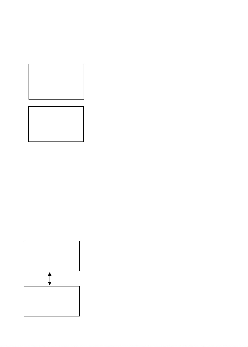
Appendix 3 - Simple Explanation on the Function of Hysteresis
SP1 Set to LO
SP2 Set to HI
RELAYON
RELAYOFF
1.
1.2
SP1
FORWARD DIRECTION
ERSE DIRECTION
RE
HYSTERESIS B
19.
SP2
ND
m
Ω
The controller relay activates when the set-po int is reached. In the reverse direction, it does not deactivate when the value reaches the set-point. Instead, it continues to be active till th e v alu e reac hes th e
amount set by the Hysteresis band.
26
Page 33

Operating Instructions αlpha-RES1000
Appendix 4 – Pure Water Curve
Resistivity of Pure Water
100
90
80
70
60
50
40
30
20
10
0
0 5 10 15 20 25 30 35 40 45 50 55 60 65 70 75 80 85 90 95 100
Temp °C
27
Page 34

Page 35

Page 36

For more information on Eutech Instruments products, contact your nearest Eutech
Instruments distributor or visit our website listed below:
Manufactured by:
Eutech Instruments Pte Ltd.
Blk 55 Ayer Rajah Crescent
#04-16/24 Singapore 139949
Tel: (65) 6778 6876 Fax: (65) 6773 0836
E-mail: marketing@eutechinst.com
Web-site: http://www.eutechinst.com
DISTRIBUTED BY:
 Loading...