

Page 1
gyM
sy...
Instruction Manual
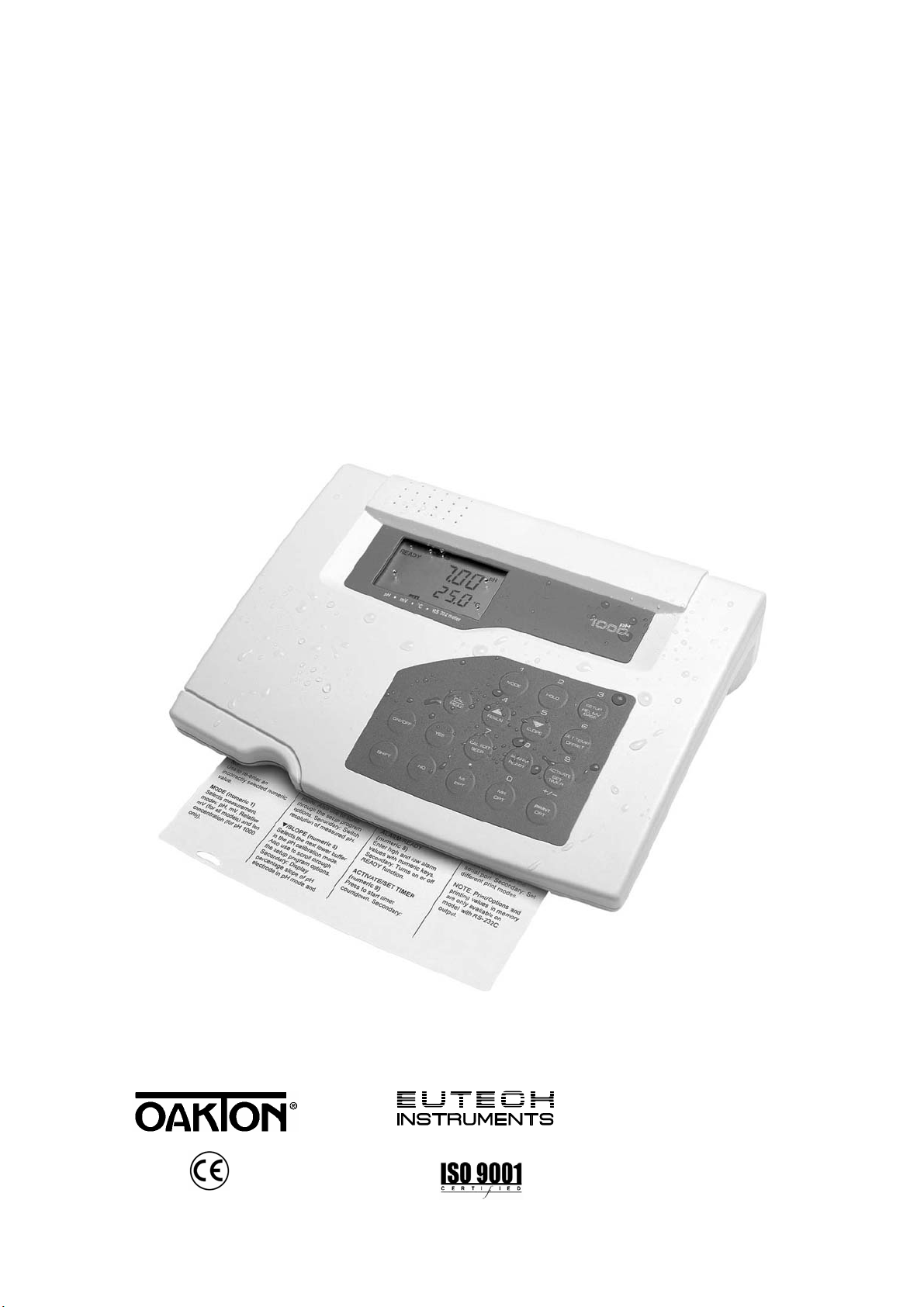
pH 1000/ pH 2500
Bench pH/Ion Meter
Technol o
adeEa
68X090800
Rev. 5 07/03
Page 2

Instruction Manual pH 1000/ 2500
Page 3

Instruction Manual pH 1000/ 2500
Preface
Thank you for choosing the pH 1000/ 2500 bench meter series.
This manual serves to explain the use of the pH 1000/ 2500 Bench meter. The manual functions in two
ways, firstly as a step-by-step operational guide to help you familiarize with the meter’s features and
functions. Secondly, it serves as a handy reference guide.
This instruction manual is written to cover as many anticipated applications and uses of the pH 1000/ 2500
bench meter as possible. If there are doubts in the use of the meter, please do not hesitate to contact the
nearest Authorized Distributors.
Eutech Instruments/ Oakton Instruments cannot accept any responsibility for damage or malfunction to the
meter caused by improper use of the instrument.
The information presented in this manual is subject to change without notice as improvements are made,
and does not represent a commitment on the part of Eutech Instruments Pte Ltd/ Oakton Instruments.
Note: Eutech Instruments Pte Ltd/ Oakton Instruments reserves the right to make improvements in
design, construction, and appearance of our products without notice.
Copyright © 1998 All rights reserved.
Eutech Instruments Pte Ltd
Oakton Instruments
Rev. 5 07/03
Page 4

Instruction Manual pH 1000/ 2500
TABLE OF CONTENTS
1 INTRODUCTION 1
2 METER INFORMATION 1
2.1 Meter Parts 1
2.2 Customized LCD 1
2.3 Slide Out Card 1
2.4 Rear Instrument Panel 1
2.5 AC/DC-Adapter 2
2.6 Electrode 2
3 KEYPAD FUNCTIONS 3
3.1 Primary & Secondary Functions of Keypad 3
4 STARTING UP THE METER 6
4.1 Connecting the Sensor Electrode 6
4.2 Connecting the Temperature Probe 6
4.3 Connecting the AC/DC Adapter 6
4.4 Connecting the Chart Recorder 6
4.5 Connecting RS232C Cable 6
5 TURNING THE METER ON AND OFF 7
6 CALIBRATION 8
6.1 pH Calibration (With ATC) 8
6.1.1 1 Point pH Calibration 8
6.1.2 Option 1 - Standard Buffers 8
6.1.3 Option 2 - Non-Standard Buffers 9
6.2 Multi-Point pH Calibration (Up to 5 Points) 9
6.3 Special Topic: CAL EDIT (for Custom/Non-Standard Buffers) 10
6.4 pH Calibration (without ATC) 10
6.5 Relative mV Calibration 11
6.6 Ion Calibration (for pH 2500 only) 12
6.7 Temperature Calibration 13
7 MEASUREMENT: READY, CONTINUOUS AND HOLD 14
7.1 Measurement in the READY Mode 14
7.2 Measuring in the Continuous Mode 14
7.3 HOLD Function 14
7.3.1 Holding and Releasing a Measured Value 14
7.4 Measuring pH 15
7.5 Measuring mV 15
7.6 Measuring Relative mV 16
7.7 Measuring Ion (for pH 2500 only) 16
8 SETUP FUNCTIONS AND KEYS 17
9 PROGRAM 1: LAST CALIBRATION TIME, DATE AND TEMPERATURE 18
10 PROGRAM 2: MEMORY RESET AND AUTO-OFF FUNCTION 19
11 PROGRAM 3: SET CURRENT TIME AND DATE 19
12 PROGRAM 4: COMMUNICATION SETUP 20
12.1 Switching pH Resolution 22
12.2 Setting the READY Indicator 22
12.3 Setting the Audible Beep 22
12.4 Viewing pH Electrode Offset 22
12.5 Viewing pH Electrode Slope 22
12.6 Viewing Ion Electrode Slope (for pH2500 only) 22
12.7 Setting the High and Low Setpoint Alarm (pH/mV/Relative mV) 23
12.8 Setting & Activating the Timer 23
12.9 Setting the Timer 24
12.10 Activating the Timer 24
12.11 Memory Input Functions and Options 25
12.12 Print Functions and Options 26
12.12.1 Print Function Options 26
13 TROUBLESHOOTING AND ERROR MESSAGES 27
Page 5

Instruction Manual pH 1000/ 2500
ELECTRODE CARE 28
14
14.1 Electrode Activation 28
14.2 Electrode Maintenance 28
14.3 Storing pH/ORP electrodes 28
15 METER SPECIFICATIONS 29
16 ACCESSORIES 30
17 WARRANTY 32
18 RETURN OF ITEMS 32
Page 6

Instruction Manual pH 1000/ 2500
1 INTRODUCTION
Thank you for selecting pH1000/ 2500 bench meter. This step-by-step instruction manual gives you a
detailed description on the use and operation of features on the meter. There are 2 models: pH1000
(pH/ mV/ Relative mV/ Temperature/ RS232C) and pH2500 (pH/ Ion/ mV/ Relative mV/ Temperature /
RS232C). These meters are designed to be user-friendly while providing unprecedented levels of
accuracy, repeatability and reliability.
The pH 1000/ 2500 bench meter is an advanced microprocessor-based (ASIC-Application Specific
Integrated Circuit) ideal for routine measurement that best meets discerning user’s individual needs.
This feature-rich meter has splash-proof keypad, simultaneous pH/ mV/ Ion and temperature display
on a large angled custom LCD. Besides, the meter allows user customization via its SETUP feature,
making the unit more powerful and user-friendly to cater to your individual needs. This instruction
manual is illustrated with useful hints and diagrams that show which specific key-presses to access for
each function.
2 METER INFORMATION
The pH 1000/ 2500 bench meter is packaged in a corrugated box which is made of environmentfriendly materials and can be re-cycled.
2.1 Meter Parts
The instrument is designed to give an aesthetic look as well as ergonomic functionality. A large
custom dual LCD is provided at an angle for optimum viewing. A splash proof keypad with audible
tactile response gives you a good feel of the instrument. A slide-out instruction card offers a handy
reference in case of doubts. Listed below are the major parts of the meter.
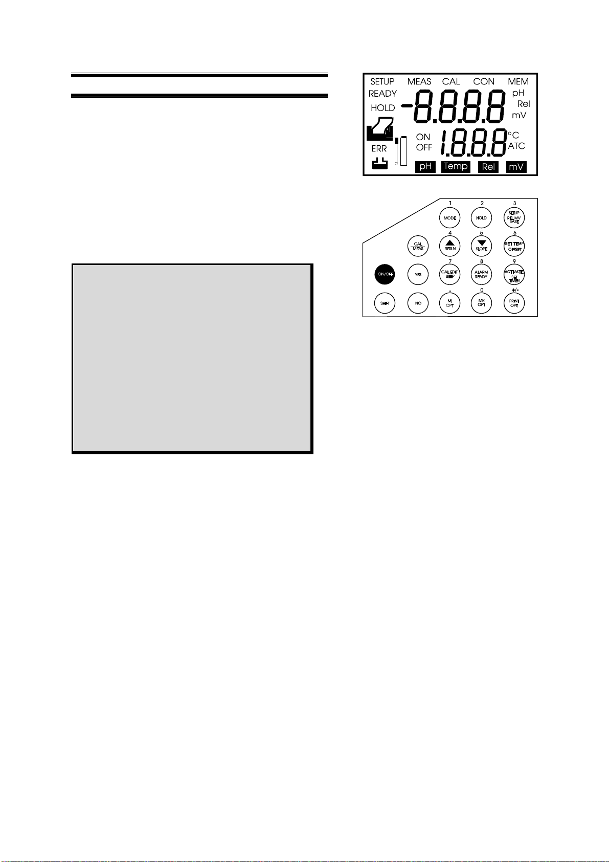
2.2 Customized LCD
The pH 1000/ 2500 bench meter is characterized by large dual custom LCD (Liquid Crystal Display).
The display has also mode annunciators for pH, temperature, relative mV and mV readings. The
secondary (lower) display shows the temperature readings simultaneously with the primary (upper)
display of measured mode. Special annunciators such as graphical symbols, error messages,
measurement units and modes of operation are arranged around the primary and secondary displays
to give a comprehensive display. The integration of graphics and error messages into the LCD
provides you a higher level of user-friendliness and easy readability.
2.3 Slide Out Card
A plastic slide out card is provided at the bottom of the bench meter. The function of this card is to
provide a quick guide to the functions of the individual keys as well as to provide a useful trouble
shooting reference.
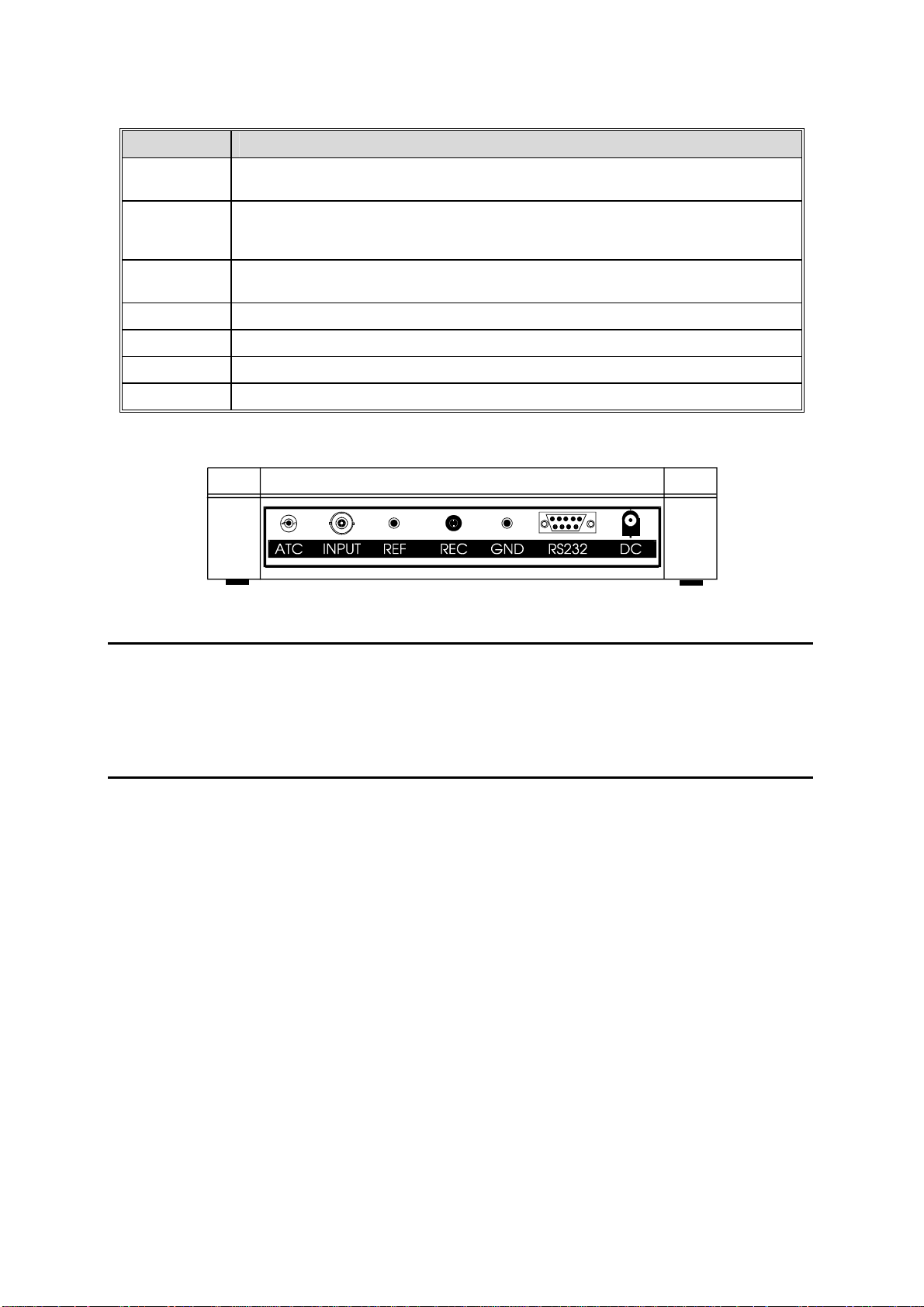
2.4 Rear Instrument Panel
The pH 1000/ 2500 bench meter provides a set of connectors for the various accessories commonly
used. In addition to all the connectors, pH 1000/ 2500 bench meter has an additional RS232C port to
allow for data transmission between the meter and a printer or computer, Furthermore; it can be
remotely controlled using a software from Eutech Instruments. Listed as follows are various
connections available.
1
Page 7
Instruction Manual pH 1000/ 2500
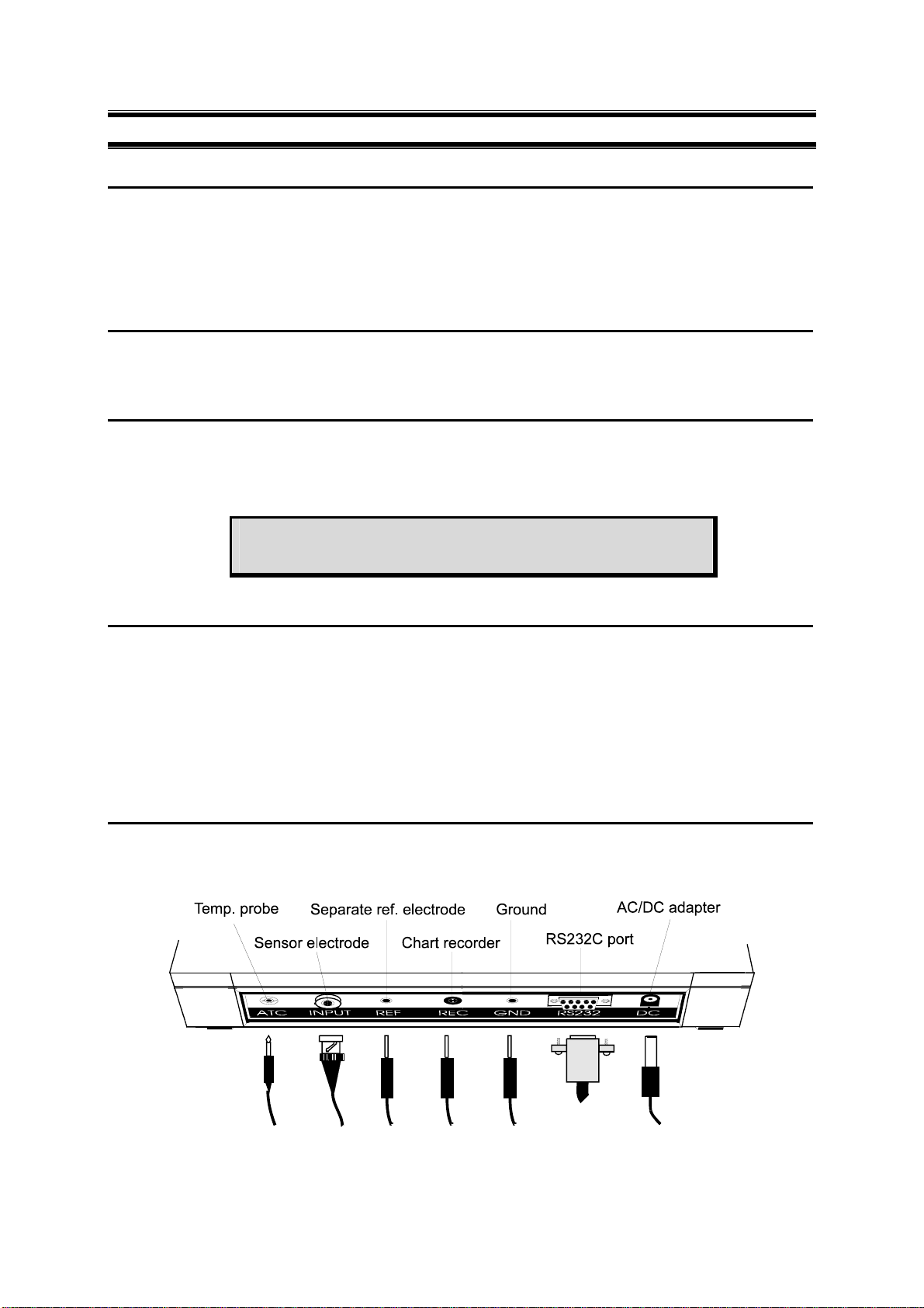
Connector Function
ATC For phono jack connection from the temperature probe for Automatic Temperature
Compensation. The probe should be a thermister type probe.
INPUT For connecting sensors with a BNC connector to the meter. The meter accepts any pH,
ORP or ISE electrode with a BNC connector. Always make sure that the connector is
clean and dry.
REF For connection to the pin tip type reference electrode normally used with half cell (mono)
type pH or ISE electrodes.
REC For connection to the strip chart recorder.
GND For connection to the ground earth jack (standard pin tip connectors).
RS232C For connection to the RS232C serial port.
DC For connection to the AC power source to the power jack (DC).
Rear View of the Meter
2.5 AC/DC-Adapter
AC/DC adapters convert the power mains voltage 120/220 VAC to low DC voltage for the pH 1000/
2500 bench meter operation. Two basic models of adapters are available depending upon power
supply specification of each country. See accessories section.
2.6 Electrode
Electrode is one of the most important parts of the meter. The electrode glass membrane is fragile and
must be handled with care. A protective rubber cap containing a suitable storage solution to protect
the glass membrane and to maintain activation of the glass membrane covers the pH electrode
provided with the meter (when ordered). A special protective guide for use during measurements is
enclosed to offer added protection against damage to the pH electrode glass bulb during operation.
Maintenance of electrode is necessary from time to time. Please refer to Section 14 on Electrode
Care.
2
Page 8
Instruction Manual pH 1000/ 2500
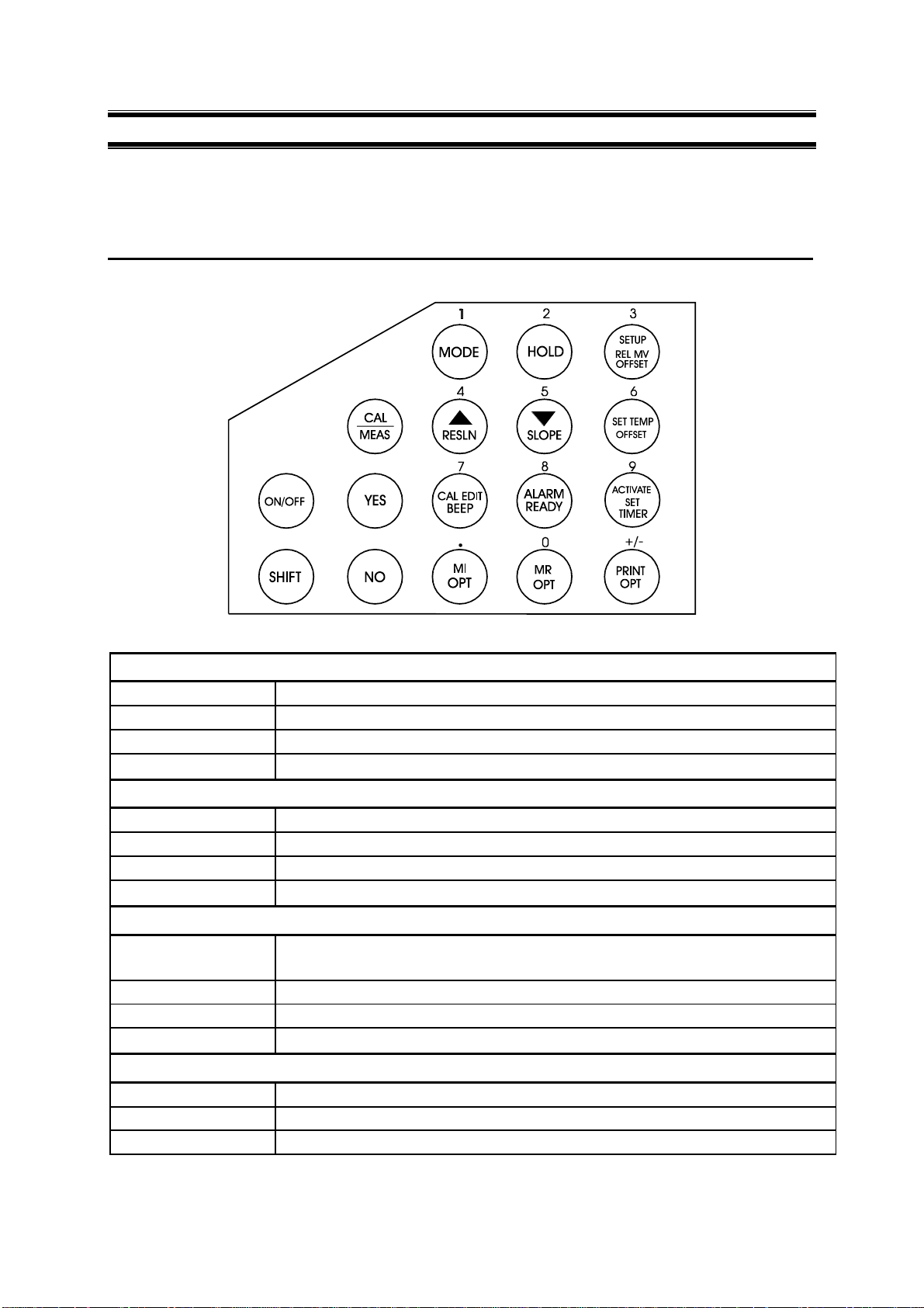
3 KEYPAD FUNCTIONS
The pH 1000/ 2500 bench meter is equipped with large tactile response keypad for ease of use. All
keys have primary function with some keys having secondary functions.
3.1 Primary & Secondary Functions of Keypad
ON/OFF
Primary Function Turns meter on or off.
Secondary Function None
Numeric Value None
SHIFT
Primary Function Press to access the secondary functions of the meter.
Secondary Function None
Numeric Value None
YES
Primary Function
Secondary Function None
Numeric Value None
Enter numeric values, confirm calibration points, or confirm and scroll program options
or values selected.
NO
Primary Function Use to cancel incorrectly selected numeric value or selection made.
Secondary Function None
Numeric Value None
3
Page 9
Instruction Manual pH 1000/ 2500
CAL/MEAS
Primary Function
Secondary Function None
Numeric Value None
Press to toggle between measurement and calibration modes of the meter - pH,
Temperature, mV, Relative mV and Ion. Also use as exit from SETUP mode,
secondary functions and to abort operation while in calibration mode.
1 / MODE
Primary Function Select one of four measurement modes: pH/mV/Relative mV/Ion.
Secondary Function None
Numeric Value 1
2 / HOLD
Primary Function Freeze the displayed value. Allow you to print the held reading or store it into memory.
Secondary Function None
Numeric Value 2
3 / SETUP / REL MV BASE
Primary Function
Secondary Function
Numeric Value 3
4 / ∆ / RESLN
Primary Function
Secondary Function Toggle the pH resolution between 0.01 pH and 0.1 pH.
Numeric Value 4
Enter SETUP mode of the meter for customization of meter functions as well as view
some diagnostic functions.
Display the Relative mV base value while in Relative mV mode and Ion Electrode
Slope while in the Ion mode.
Select next higher pH buffer values in the pH calibration mode. Also used to scroll
through SETUP mode options.
5 /∇ / SLOPE
Primary Function
Secondary Function
Numeric Value 5
Select the next lower pH buffer value option in pH calibration mode. Also used to
scroll through some SETUP mode options.
Display the percentage slope of the pH electrode when in the pH mode. While in Ion
mode, it displays slope of ion electrode in mV/decade.
6 / SET TEMP / OFFSET
Primary Function Press to calibrate ATC temperature probe or to set manual temperature.
Secondary Function
Numeric Value 6
Displays the offset of pH electrode. This is useful as a diagnostic function to
determine the quality of the probe that is connected to the meter.
4
Page 10
Instruction Manual pH 1000/ 2500
7 / CAL EDIT / BEEP
Primary Function Press to edit pH buffer value while you are in pH calibration mode.
Secondary Function Turns on or off ‘beep’ sound whenever a key-press is depressed.
Numeric Value 7
8 / ALARM / READY
Primary Function Enter the high and/or low alarm values.
Secondary Function Turns on or off the READY function.
Numeric Value 8
9 / ACTIVATE / SET TIMER
Primary Function Press to start timer countdown.
Secondary Function Sets the time interval.
Numeric Value 9
. / MI / OPT
Primary Function Stores the displayed value into memory.
Secondary Function Activate different Memory Input Options, these include:
Numeric Value . (decimal point)
Data Log on Ready
Data Log on Time Interval
Set Time Interval for Data Log
0 / MR / OPT
Primary Function Recalls stored values from the memory in the Last-In-First-Out (LIFO) sequence.
Secondary Function Activate different Memory Recall options. There are two options:
Numeric Value 0
Print all memory data
Clear memory
+/- / PRINT / OPT
Primary Function Output the displayed data through the serial/RS232C port. Can be activated in the
Secondary Function Sets the different print options. There are three options:
Numeric Value +/-
measurement, HOLD functions and memory recall functions.
Print on ready
Print on time interval
Set print time interval
5
Page 11
Instruction Manual pH 1000/ 2500
4 STARTING UP THE METER
4.1 Connecting the Sensor Electrode
Slide the sensor electrode connector of the electrode over the INPUT BNC socket. Then push the
connector into the socket and turn the connector clockwise to lock into position. Do not use excessive
force. This applies to combination pH/ORP/ISE electrodes. For half-cell sensors where a reference
electrode is used, connect the sensor connector to socket marked (REF). Always ensure that the
connectors are dry when connection is done.
4.2 Connecting the Temperature Probe
The temperature probe uses a phono jack to connect with the socket marked ATC on the meter. Insert
the jack directly into the socket until it is firmly seated.
4.3 Connecting the AC/DC Adapter
Ensure that the power to the AC/DC adapter is switched off. Slide the AC/DC adapter jack into the
socket marked DC of the meter until it is firmly seated. For AC/DC adapter always ensure that the
power mains voltage matches that of the adapter used. AC/DC adapters used should have the
following specifications or settings. Output:- Voltage: 9 V DC Current: 500 mA.
NOTE: Ensure that the input power mains voltage (120/220 V)
matches your adapter requirements.
4.4 Connecting the Chart Recorder
The meter provides a recorder output of +/- 2000 mV for transmission of readings either to a chart
recorder or to a data acquisition device (Analog/Digital Cards). When the chart recorder is in
operation, continuous absolute mV readings will be charted. Note that readings are independent of the
operating mode and is uncompensated and set to a one to one (1:1) ratio.
Where the charting is made in reference to ground potential, a cable is connected from the GND port
of the meter to the chart recorder. Plug the phono connector to the meter at the designated port
(marked REC). The tip (inner) connection should be wired to the high side of the recorder and the
sleeve (outer) side should be wired to the low side of the recorder.
4.5 Connecting RS232C Cable
Noting the orientation of RS232C connector, insert the 9-pin male connector from your device (a
printer or computer) into the RS232C port (marked RS232) of the meter. Fasten the RS232C
connector using the two screws at the side of the male RS232C connector. Do not over-tighten.
6
Page 12
Instruction Manual pH 1000/ 2500
5 TURNING THE METER ON AND OFF
Once the AC/DC adapter is connected and powered on,
the meter beeps and the full LCD lights up for a few
seconds to display all segments as a self-diagnostic
test of the LCD. Then the meter will display the current
time.
To access the meter functions, press ON/OFF key. The
meter beeps and performs a diagnostic test before
going into the pH measurement [MEAS] mode. To turn
the meter off, press ON/OFF key within the operation
mode. The meter performs a self-diagnostic LCD test
before displaying the current time.
IMPORTANT :
Remember to remove the protective cap from
the electrode tip prior to measurement.
Replace it in place after use or store electrode
in some storage solution to avoid possible
dehydration of glass bulb which may result in
slow response.
In any case if the electrode is not i n use for
long period, condition the electrode by
soaking into tap water for 1-2 hours before use.
Make sure to wash electrodes/probes
before/after each sample measurements to
prevent any carry-over of samples.
7
Page 13
Instruction Manual pH 1000/ 2500
HINT: For best results, perform
at least a 2-Point Calibration
using buffers that bracket the
expected range of
measurement. If a 1 Point
Calibration is to be used, it is
highly recommended that
measurement be performed
only at points close to the
calibration value.
The primary display of the LCD shows
the measured pH value; the
secondary display shows the value of
the standard solution (pH 1.68, 4.01,
7.00, 10.01, 12.45). To select other
buffer values, use arrow keys.
Note: The LCD will display
the actual pH value of
the buffer at the point of
calibration. For example,
a pH 10.01 (@ 25 oC)
buffer when calibrated at
20 oC will actually have a
value of pH 10.06.
Therefore, the meter will
display this value of 10.06.
6 CALIBRATION
6.1 pH Calibration (With ATC)
The pH 1000/ 2500 bench meter is capable of multi-point
calibration up to 5 points for enhanced full range accuracy
using standard pH buffer options at pH 1.68, 4.01, 7.00,
10.01 and 12.45. In addition, these meters allow added
flexibility for you to calibrate using other non-standard
calibration buffers (via the CAL EDIT feature).
6.1.1 1 Point pH Calibration
1. Make sure the meter is ON and if necessary, press the MODE
key to select pH mode. The pH indicator appears in the upper
right hand corner of the display.
2. Rinse the electrode thoroughly with deionised water or a rinse
solution. If using the ATC function with a separate temperature
probe, rinse the temperature probe as well. DO NOT wipe both
probes dry as it will cause a build-up of static and create
instability in calibration and measurement.
3. Select the pH buffer and pour some into a clean container.
Immerse both probes into the selected buffer and press CAL
key, a [CAL] annunciator appears. The primary display shows
the measured pH reading while the secondary display indicates
the pH buffer value for calibration.
4. Select the correct buffer value on the meter. If the buffer used
is a standard value, use OPTION 1. Otherwise use OPTION 2
to calibrate the meter to the required value.
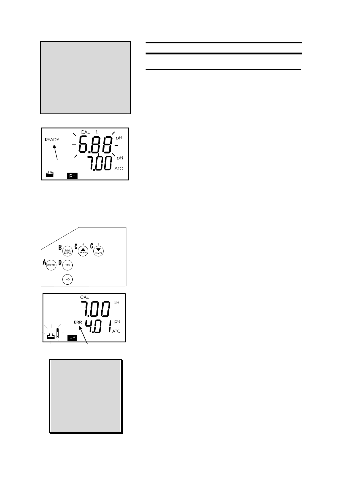
6.1.2 Option 1 - Standard Buffers
Select desired pH buffer standard using
to the correct buffer value as indicated in the secondary
display to that of the prepared buffer solution.
If the selected buffer is not within the accepted window (see
below) from the measured pH value, the electrode and
buffer icons flash and [ERR] annunciator appears next to the
secondary display.
Window of Accepted Values:
pH 1.68 ±1.00 pH 10.01 ±1.00
pH 4.01 ±1.00 pH 12.45 ±1.00
pH 7.00 ±1.50
1. When reading stabilizes, a [READY] annunciator is displayed
on left hand side of the LCD. Note the READY annunciator will
be displayed after you have activated this function prior to
measurement or calibration. For details refer to Section 7.1.
2. Press YES to confirm calibration or NO to cancel and re-enter.
Upon confirmation, the CON indicator flashes at the top right
hand side of the LCD to indicate that the instrument is now
calibrated to the selected buffer. The secondary display
automatically scrolls to the next pH buffer option.
3. You have performed one-point calibration successfully using
standard buffer option after pressing YES key. To resume to
measurement mode, press CAL/MEAS key while you are in
the calibration mode.
S or Tkey to scroll
8
Page 14
Instruction Manual pH 1000/ 2500
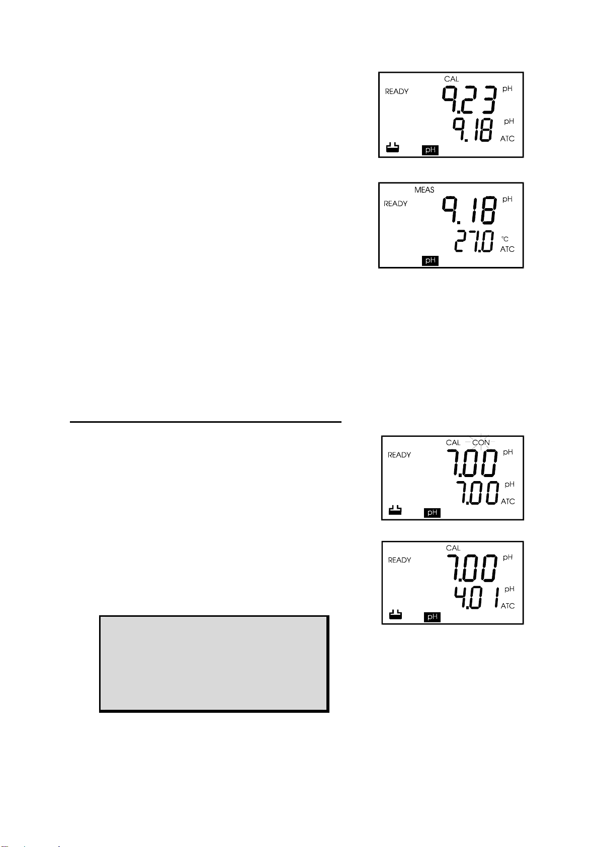
6.1.3 Option 2 - Non-Standard Buffers
1. Press CAL EDIT key after entering into pH calibration mode.
The buffer icon blinks at the bottom left hand corner of the
LCD. Select the buffer value by entering the value directly via
the keypad numeric keys. For example, 9.18. The value
entered is displayed in the secondary display. Please ensure
the correct pH buffer sample is available during calibration.
2. When reading stabilizes, a [READY] annunciator is displayed
on left hand side of the LCD. Note this READY annunciator will
be displayed after you have activated this function prior to
measurement or calibration. For details refer to Section 7.1.
3. Press YES to confirm calibration or NO to cancel and re-enter.
Upon confirmation, the CON indicator flashes at the top right
hand side of the LCD to indicate that the instrument is now
calibrated to the selected buffer. The secondary display
automatically scrolls to the next pH buffer option.
4. You have performed one-point calibration using non-standard
buffer option successfully after pressing YES key. To resume
to measurement mode, press CAL/MEAS key while in the
calibration mode. The primary display shows the calibrated pH
buffer value (in this case, pH 9.18) and the secondary display
shows the measured temperature value.
6.2 Multi-Point pH Calibration (Up to 5 Points)
1. Follow steps 1 to 4 of “1 Point Calibration”.
2. If your 1 Point Calibration began with the default buffer value of
pH 7.00 (@ 25
next value, pH 4.01. The next value automatically shown is
1.68 after which the value scrolls round to 12.45 and then
10.01 and back again to 7.00.
3. T o select the second buffer you wish to calibrate at, use S or
T key to scroll through the buffer options.
4. Follow steps (2) to (4) of the 1 Point Calibration procedure until
the entire buffer values that you wish to calibrate are complete.
Do not press CAL/MEAS key until all calibration is complete.
5. Press CAL/MEAS key when all calibrations are complete to
return to the measurement mode. Display now shows MEAS.
o
C), then the meter automatically scrolls to the
Important: OR Indicator
The ERR indicator flashes if the buffer val ue is
not within +/-1 pH of the measured buffer
value. This indicator also flashes if the buffer
value is different from that shown on the
secondary display.
9
Page 15
Instruction Manual pH 1000/ 2500
6.3 Special Topic: CAL EDIT (for Custom/Non-
Standard Buffers)
The pH 1000/ 2500 bench meter allows non-standard or
custom buffer solutions to be used for calibration. This is
especially useful in applications where the use of special or
non-standard pH buffer solution is required. To use, follow
the steps as described.
1. When in the CAL (pH) mode, press CAL EDIT key. Refer to
section 6.1.3 for further details.
2. The buffer icon at the bottom of the LCD blinks.
3. Enter the desired pH value using the numeric keys.
4. Confirm calibration by pressing YES or NO to re-enter the
value.
5. To enter another non-standard value, repeat steps 1 to 4
again.
NOTE :
As the buffer value entered in the CAL ED IT
mode is non-standard, the meter will not retain
that buffer as an option in future calibrations.
You have to re-enter the value of the buffer.
The division of the calibration ranges to a pH
range within +/1 pH of the standard buffer
options ensures that only one point can be
calibrated in any one of the five ranges.
6.4 pH Calibration (without ATC)
Manual Temperature Compensation (MTC) is done by
manually setting the temperature to that of the buffer prior to
calibration. The procedure to set the temperature is outlined
in the section on Temperature Calibration.
Set the desired temperature value in the meter using
software calibration procedure outlined in the Temperature
Calibration. Calibrate for pH using the steps for pH
calibration (ATC) using steps (1) - (5) of Multi-point pH
Calibration.
IMPORTANT: For manual compensation, the temperature
probe must be disconnected. The ATC annunciator is not
displayed on the right hand side of LCD when in calibration
and measurement modes.
10
Page 16

Instruction Manual pH 1000/ 2500
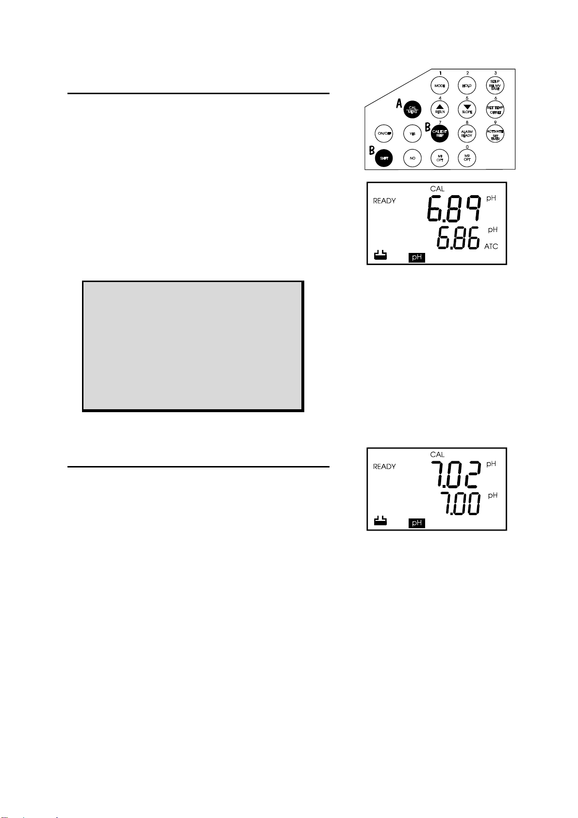
6.5 Relative mV Calibration
Relative millivolt calibration is normally used for Redox
sensors in which you set a base value. For the selection
and preparation of appropriate calibration solutions,
consult the instruction manuals for the Redox/ORP
electrodes.
1. Make the appropriate electrode connections and switch on the
meter.
2. Select [Rel] [mV] mode by pressing MODE key repeatedly until
the Relative mV mode is accessed.
3. Press CAL/MEAS key to activate calibration mode. The [CAL]
annunciator displays on top of the LCD. The LCD displays the
absolute mV reading.
4. Select the Base Offset value using the numeric keys. The
resulting value displayed in the measurement mode, is
[Absolute mV displayed] - [Base Offset]. Once this value is
entered, the Redox/ORP probe is calibrated to the selected
standard.
5. Press YES to confirm selected value or NO to cancel and re-
enter the value. If calibration has been successfully performed,
the meter is now calibrated for relative mV measurements.
6. Press CAL/MEAS key to return to the measurement mode. The
primary display shows the measured relative mV readings.
Hint 1: To set the Relative mV offset to 0.0 using the
present calibration solution, proceed to step (5) without
entering any value.
Hint 2: For Redox/ORP calibration, set the Relative mV
offset using the following equation:
[ Relative mV Offset ] = [Displayed Value] - [Value of
Standard/Desired Value]
Hint 3: To recall the selected Base Offset, press SHIFT and
followed by Relative mV Base key on the keypad.
11
Page 17

Instruction Manual pH 1000/ 2500
6.6 Ion Calibration (for pH 2500 only)
Ion calibration is used for ion selective electrodes (ISE). For
the selection and preparation of appropriate calibration
solutions, consult the instruction manuals for the list of ISE
probes and calibration standards available.
1. Make the appropriate electrode connections and switch on the
meter.
2. Select mode by pressing MODE key repeatedly until the Ion
mode is accessed, as indicated in the LCD. Dip electrode(s) in
first standard.
3. Press CAL/MEAS key to activate calibration mode. The ‘CAL‘
indicator displays on the LCD. Top display shows measured
mV value from electrode and bottom display shows 1 indicating
first standard.
4. Once the ‘READY’ indicator displays, press CAL EDIT key to
enter the concentration value of the standard. Use numeric
keys to enter the value 0 to 9999. When entering concentration
value, if decimal point is pressed, then rest of the digits (total 4
digits) must be entered e.g. 10 or 10.00. The available
calibration options include 0.1; 1.0 or 1; 10.0 or 10; 100.0 or
100 and 1000. Refer to below notes for details.
5. Press YES to confirm the selected value or NO to cancel and
re-enter the value.
6. For the next calibration value, wash electrode with deionised
water and dip it into second standard and repeat step 4.
Proceed to next calibration points until you have finished. Press
CAL/MEAS key to switch to measurement mode if calibration is
done using less than 5 standards.
7. At the end of fifth standard ion calibration, the meter switches
to [MEAS] mode automatically once these values are entered.
The ISE probe is calibrated to the selected standard solutions
.
NOTE: Minimum number of calibration for Ion is 2
points, maximum is 5 points. At least 2 standards
(preferably one decade apart in concentration
value) must be used to complete the calibratio n.
If less than 2 standards are used then calibration is
ignored. Refer to Troubleshooting
IMPORTANT :
Make sure to wash electrode between samples to
prevent cross-contamination. It is advisable to
read samples in the order of low concentration to
high concentration.
12
Page 18

Instruction Manual pH 1000/ 2500
6.7 Temperature Calibration
In this calibration procedure, the ATC probe is attached to the
meter and the ATC annunciator displays on the right hand
side of the LCD.
1. Dip the temperature probe into a solution of known temperature,
such as a temperature bath for a few minutes until the
temperature probe stabilizes. Determine the temperature of the
sample to be measured using an accurate thermometer.
2. To perform temperature calibration, press MODE key to select
the temperature mode.
3. Press SET TEMP to set the desired temperature to match that
measured value. The CAL annunciator lights up.
4. Select the temperature value using the numeric keys.
5. Press YES to confirm the selected temperature. The CON
annunciator flashes for one second and disappears. The meter
reverts to the pH measurement mode. The temperature is now
set to the temperature selected. Note: Temperature can only be
set between -9.9
o
C to 110.0 oC.
IMPORTANT :
Always conform to the temperature limits of the
sensor probe (e.g. epoxy pH probes with a built in
temperature sensor should not be used or
calibrated at temperatures above 80 oC.) If
unsure, check with specifications of the probe.
13
Page 19

Instruction Manual pH 1000/ 2500
7 MEASUREMENT: READY, CONTINUOUS
AND HOLD
7.1 Measurement in the READY Mode
The READY annunciator appears the readings are stable at
the top left corner of the LCD. The reading is held as long as
the variation of readings is within a range. (For pH, tolerance
is +/- 0.02 pH. For mV, tolerance is +/- 0.3 mV < 400 mV and
+/- 1.2 mV > 400 mV).
1. Rinse the pH electrode using de-ionized or distilled water prior to
use. This will remove impurities that have adhered on the
electrode body.
2. Switch to the MEAS mode for measurement. The MEAS mode is
activated whenever the meter is switched on. If you are in the
calibration mode, press CAL/MEAS key to revert to the
measurement mode.
3. Dip the electrode into the sample ensuring that the glass bulb of
the electrode is completely immersed into the sample. Swirl
electrode gently in the sample. When reading stabilizes, the
READY annunciator displays.
NOTE:
If the READY indi cator is turned off, the readings are
instantaneous readings. Allow readings to stabilize
before reading for highest accuracy.
7.2 Measuring in the Continuous Mode
As the READY function provides stable readings, the
continuous mode provides instantaneous readings for faster
operation. Continuous mode readings, however, may not be
as stable. To turn off READY, see page 22. Follow steps (1)
to (3) of READY mode measurements.
7.3 HOLD Function
This feature allows you to hold the value of the measurement
reading until it is more convenient to note the reading. This
mode can be activated at any time when you are in the MEAS
mode. You can store the held value into memory if HOLD is
active.
7.3.1 Holding and Releasing a Measured Value
In the measurement mode, press HOLD key to hold a
displayed value. When HOLD mode is activated, the HOLD
mode annunciator displays.
To release a held value, press HOLD key again. The HOLD
mode annunciator disappears from the LCD and the meter
reverts to its measurement mode.
14
Page 20

Instruction Manual pH 1000/ 2500
7.4 Measuring pH
The meter automatically goes to the pH measurement mode
when you power it on.
1. If you are not in the pH measuring mode, press MODE key until
the mode annunciator at the bottom of the LCD shows that the
meter is in the pH mode.
2. To measure in READY mode, follow steps (1) to (3) of the steps
in “Measuring in the READY Mode”.
3. The primary display shows the pH reading and the secondary
field shows the temperature.
7.5 Measuring mV
1. If you are not in the mV measuring mode, press MODE key until
the mode annunciator at the bottom of the LCD shows that the
meter is in the mV mode.
2. To measure in READY mode, follow steps (2) to (3) of the steps
in “Measuring in the READY Mode”.
3. The primary display shows the mV reading and the secondary
field will show the temperature. The resolution will be 0.1 mV
within the +/-399.9 mV range and +/-1 mV beyond. Beyond the
operation range of the meter, it will show “Ur” and “Or” in the
primary display to denote under range and over range
respectively.
NOTE:
Electrode can be attached to an electrode
holder for a more stable operation.
Remember to remove the rubber cap from the
electrode tip prior to measurement.
15
Page 21

Instruction Manual pH 1000/ 2500
7.6 Measuring Relative mV
1. If you are not in Relative mV measuring mode, press MODE key until
the mode annunciator at the bottom of the LCD shows that the meter
is in the Relative mV mode.
2. To measure in READY mode, follow steps (2) to (3) of the steps in
“Measuring in the READY Mode”.
MODE
HOLD
3. The primary display shows the corrected Relative mV reading and the
secondary field shows the temperature. The resolution will be 0.1 mV
within the +/-399.9 mV range and +/-1 mV beyond. Beyond the
operation range of the meter, it shows “Ur” and “Or” in the primary
display to denote under range and over range respectively.
4. The displayed value is actually the result of subtracting the base mV
value (Set by yourself; see Calibrating Relative mV in Section 6.5)
from the absolute mV reading. The default setting of this base value is
0 mV.
To recall the base value set, press SHIFT followed by Rel mV key.
7.7 Measuring Ion (for pH 2500 only)
If you are not in the Ion measurement mode, press MODE key
until the mode annunciator at the bottom of the LCD shows that
the meter is in the Ion mode.
To measure in READY mode, follow steps (2) to (3) of the steps in
“Measuring in the READY Mode”. The primary display will show
the Ion reading and the secondary field will show “Ion”.
While measuring between samples, remember to rinse the
electrode with deionized water before proceeding to the next
sample, to avoid cross-contamination if any.
16
Page 22

Instruction Manual pH 1000/ 2500
8 SETUP FUNCTIONS AND KEYS
The advanced SETUP mode allows user customization of the
meter’s operation to individual’s preferences and defaults.
To enter into the SETUP mode, press the SETUP key while in any
measurement mode.
S or T key to select options if changes are required.
Use
Press YES key to confirm selection in each program. The display
will automatically scroll to the next program in sequence. At the
last program option, pressing YES will return control to
measurement mode.
To exit program at any time, press CAL/MEAS key.
Three types of setting/operating information for all
programs:
Meter Operations :
Activating Auto Off functions;
Time & Date Setting;
Memory Reset.
Diagnostic Information:
Last Calibration Date and Time;
Calibrated Buffer Points;
Last Calibrated Temperature.
Communication Data Protocol (with a
printer or computer):
Baud Rate;
Parity Bit;
Stop Bit.
17
Page 23

Instruction Manual pH 1000/ 2500
9 PROGRAM 1: LAST CALIBRATION TIME, DATE
AND TEMPERATURE
This program allows you to view the last pH calibration performed time and date (month, day and year). Calibrated pH buffer and
temperature values are also available for viewing.
Program 1.0: Last Calibration Time
Viewing only. No options. Press YES to go to next program.
Program 1.1: Last Calibration Month
Viewing only. No options. Press YES to go to next program.
Program 1.2: Last Calibration Date
Viewing only. No options. Press YES to go to next program.
Program 1.3: Last Calibration Year
Viewing only. No options. Press YES to go to next program.
Program 1.4: Calibrated Buffers
Viewing only. Displays all buffer values which have been calibrated at.
Use S or T key to scroll through values. If no buffers were calibrated,
the display shows “- - - - ”. No options. Press YES to go to next program.
Program 1.5: Last Calibration Temperature
Viewing only. Displays the temperature at which the meter was
calibrating. Default setting is 25
program.
o
C. No options. Press YES to go to next
18
Page 24

Instruction Manual pH 1000/ 2500
10 PROGRAM 2: MEMORY RESET AND AUTO-
OFF FUNCTION
This program allows you to clear all the memory stored and to
activate the Auto-Off function.
Program 2.0: Memory Reset
Selecting ON clears all data in memory including pH calibration data and
also Relative mV calibration data. The meter automatically switches off
and the clock appears. To proceed, switch the meter on again. If reset is
required, press S or T to select the ON option and confirm by pressing
YES.
Program 2.1: Auto Off
This function is present to conserve energy by shutting off the meter after
30 minutes from the last key is pressed. Factory default sets this option to
ON. Press S or T key to select option and confirm by pressing YES.
11 PROGRAM 3: SET CURRENT TIME AND DATE
This program is used to set the current date and time of the meter.
The values will be stored and displayed once it is entered into
memory, unless the meter is set to default settings.
Program 3.0: Display and set time
Use numeric keys to set time. Press YES to confirm.
Program 3.1: Display and set month
Use numeric keys to set time. Press YES to confirm.
Program 3.2: Display and set date
Use numeric keys to set time. Press YES to confirm.
Program 3.3: Display and set year
Use numeric keys to set time. Press YES to confirm.
19
Page 25

Instruction Manual pH 1000/ 2500
12 PROGRAM 4: COMMUNICATION SETUP
Program 4 allows you to retrieve SETUP settings as well as to set up
communication parameters for connection to external devices such
as the printer or PC. Set the options to match with other optional
devices.
Program 4.0: Meter Setup Printing
Select the ON option using S or T key if you want the settings as well as
all calibration data to be printed out via the RS232C port. This is useful
for you to see all setup functions at a glance.
Program 4.1: Baud Rate
Press YES. Default is 9.6 Kbps.
Program 4.2: Parity Bit
Press YES. Default is 2 (even).
Program 4.3: Stop Bit
Press YES. Default is 2.
The meter then automatically returns to the measurement mode.
20
Page 26

Instruction Manual pH 1000/ 2500
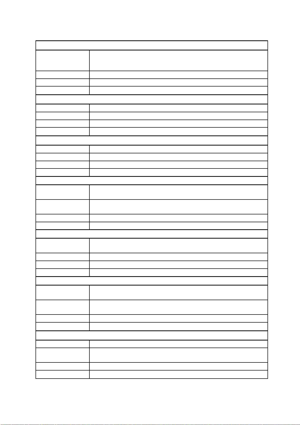
SUMMARY OF SETUP OPTIONS
Program Function Active Keys Options Factory Defaults
Last pH Calibration Information
P1.0 Last Calibration Time - - P1.1 Last Calibration Month - - P1.2 Last Calibration Date - - P1.3 Last Calibration Year - - P1.4 Last Calibration
Temperature
P1.5 Display Calibrated Points S or T Only calibrated points
Memory Reset, General Meter Operation
P2.0 Auto-Off
P2.1 Reset Meter
Current Date & Time Setting
P3.0 Set Current Time Numeric Keys - 08.30
P3.1 Set Current Month Numeric Keys - 11
P3.2 Set Current Date Numeric Keys - 10
P3.3 Set Current Year Numeric Keys - 93
Communication Setup
P4.0 Print SETUP options
P4.1 Select Baud Rate
P4.2 Select Parity
P4.3 Select Stop Bits
- - -
“- - - - ” No
S or T
S or T
S or T
S or T
S or T
S or T
will be displayed.
ON/OFF ON
ON/OFF OFF
ON/OFF OFF
- 9.6
- 2
- 2
Calibration.
When using the Setup Functions:
Use S or T key to toggle between options; or use the numeric keys to input
numbers. Note that certain setup functions provide information only, and
have no customizing options.
21
Page 27
Instruction Manual pH 1000/ 2500
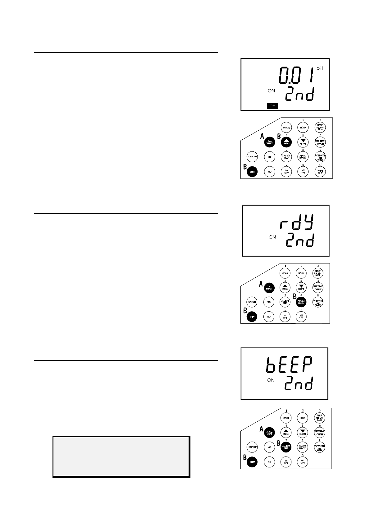
12.1 Switching pH Resolution
Ensure that you are in the pH measurement mode. It does not
matter which measurement mode you are in as the meter only
toggles the pH resolution (as the resolution of mV and Relative
mV settings is automatically set).
Press SHIFT and then RESLN key. The LCD shows the resolution
to be set. After two seconds the meter reverts to its normal
operation.
Each time this function is activated, the meter automatically
switches between the two resolution options provided (0.01 and
0.1).
12.2 Setting the READY Indicator
The READY indicator is displayed whenever the readings stabilize
to within +/-0.02 pH tolerance (for pH measurements) or a
tolerance mV level of +/- 0.8 mV for < +/-400 mV and +/- 1.2 mV >
+/-400 mV (for mV and Relative mV measurements).
Ensure that you are in the any measurement mode.
Press SHIFT and then READY key. The LCD will show the
READY option to be set.
Each time this function is activated, the meter automatically
switches between READY ON and READY OFF. After two
seconds the meter will revert to normal operation.
12.3 Setting the Audible Beep
If the BEEP function is ON, the meter beeps every time a key is
pressed. The beep can also be turned off using this function.
1. Ensure that the meter is in any measurement mode.
2. Press SHIFT and BEEP. The LCD shows the BEEP option to be set
(ON or OFF).
3. Each time this function is activated, the meter automatically switches
between BEEP ON and BEEP OFF. After two seconds the display
then reverts to its normal operation.
NOTE:
The meter will automatically toggl e between
BEEP ON and BEEP OFF every time this function
is accessed.
22
Page 28
Instruction Manual pH 1000/ 2500
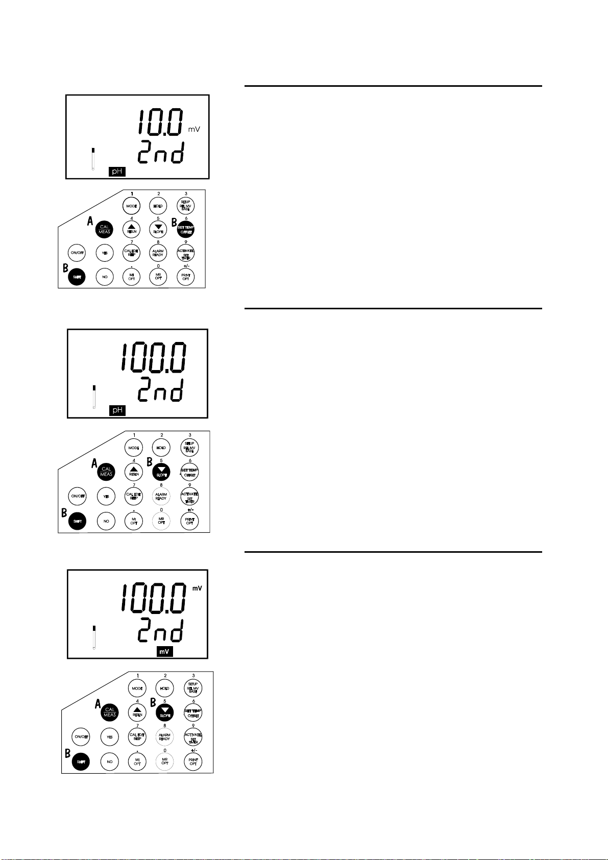
12.4 Viewing pH Electrode Offset
This function is diagnostic in nature and allows you to view the
offset of the pH electrode in mV. The offset is based on the pH
7.00 buffer calibration. If the calibration has yet to be performed
at this pH, the meter shows 00.0 mV (which is the ideal). The mV
shows the efficiency of the electrode and how much the meter
has to compensate for it. Generally a value of +/- 15 mV is
acceptable with the ideal being 0.0 mV.
1. Ensure that you are in the pH measurement mode.
2. Press SHIFT and OFFSET. The LCD shows the offset of the pH
electrode.
12.5 Viewing pH Electrode Slope
This diagnostic function allows you to view the slope of the pH
electrode based on the Nerstian equation. Slope displayed is the
average slope based on calibrations. If no calibration has been
performed or if the meter has been reset in the SETUP function,
the meter shows the default value of 100.0%.
1. Ensure that the meter is in the pH measurement mode.
2. Press SHIFT and then SLOPE key. The LCD shows the slope
percentage of the pH electrode. After two seconds the display
then reverts to its normal operation.
12.6 Viewing Ion Electrode Slope (for pH2500 only)
Similarly, in the Ion mode, you can view the slope of Ion
electrode. Slope is displayed as mV per decade. If no calibration
has been performed or if the meter has been reset in the SETUP
function, the meter shows the default value of “- - - -“.
1. Ensure that the meter is in the Ion measurement mode.
2. Press SHIFT and SLOPE. The LCD shows the slope of the Ion
electrode in mV/decade. After two seconds the display then reverts
to its normal operation.
22
Page 29

Instruction Manual pH 1000/ 2500
If you wish to skip input for
either the High/Low
setpoint, press YES key.
Meter automatically exits to
measurement mode.
12.7 Setting the High and Low Setpoint Alarm
(pH/mV/Relative mV)
An alarm can be set to give an audible warning to you whenever
the set limits for pH, Relative mV or mV has been exceeded.
Hint: You can set individual high and low setpoints
for each of the measurement modes of pH,
Relative mV and mV. The individual setpoint alarms
will be automatically acti vated whenever the
measurement mode of the set alarm is entered.
1. Press ALARM. The meter will prompt for the setting or changing of
the setpoint. If no setpoint is set, the meter displays “- - - -”.
Otherwise the old setting is shown.
2. Enter the high setpoint using the numeric keys. To erase a setpoint,
press +/- key twice.
3. Confirm using YES key. To cancel and re-enter press NO. Meter will
advance to low setpoint upon confirmation of value.
4. Repeat steps 2 and 3 for the low setpoint setting. Meter then reverts
to the measurement mode.
Hint: To shut off an alarm, go back into the ALARM
function and press +/- key twice at the setpoint
options. The alarm will then shut off.
12.8 Setting & Activating the Timer
The meter can be set to hold a reading at a particular time until it
is read. This is done by first setting the timer countdown and
activating it using the ACTIVATE key. At the time set, the meter
holds the reading (until any key is pressed and gives a continuous
beep to signal to you that the time set is reached.
23
Page 30

Instruction Manual pH 1000/ 2500
12.9 Setting the Timer
From the MEAS mode, press the SHIFT followed by SET TIMER
key. The meter shows that the secondary function is on. If no time
has been set, the LCD displays “- - - -”.
Use the numeric keys to enter the time required. Press YES to
confirm or NO to re-enter value.
Upon confirmation, the meter returns to the measurement mode.
Note: The ti mer is NOT acti vated until you press the ACTIVA TE key
on the keypad.
12.10 Activating the Timer
1. From the MEAS mode, press the ACTIVATE key to start timer
countdown. The [MEAS] indicator flashes to indicate that the timer is
on.
2. At the end of the time period, the alarm beeps to indicate that time is
up. Press any key to switch off alarm.
To restart timer, press the ACTIVATE key again. To clear the
timer, go to “Setting the Timer” and clear the time by pressing +/-
key twice and confirming with YES.
24
Page 31

Instruction Manual pH 1000/ 2500
12.11 Memory Input Functions and Options
The meters can store up to 16 sets of values (pH/mV/Relative mV
together with temperature). The Last-In-First-Out (LIFO) method of
the memory management is used. When the memory is full, the
value stored in the first memory location will be erased to create
space for the new input value.
1. During any measurement operation, press MI.
2. The MEM annunciator flashes to indicate that the data has already
been stored into memory.
Memory Options
To access two MI options, press SHIFT followed by MI/OPT.
1st Option: Memory Input When Ready
The factory default setting is OFF. When turned ON, the meter
automatically stores the reading into memory when the READY
indicator is displayed.
Use S or T key to turn on or off the MI READY option. Press YES to
confirm. Meter advances to the second option.
NOTE : To activate the MI READY option successfully,
the READY mode must be ON prior to setting MI READY
(See switching on READY mode). If not, go back to
setting the READY on before returni ng to this option.
2nd Option: Input Time Interval
This option allows you to input readings into the memory at a user
selected time interval (between 1 minute to 23 hours 59 minutes).
Default is “- - - -“.
To access memory input on time interval function:
1. Press SHIFT and then MI. The first option READY appears.
2. Press YES to proceed to the next option - time interval function.
3. Enter the desired time interval using the numeric keys followed by
YES to confirm. To cancel an entry before confirming, press NO and
re-enter value before confirming. Meter will return to the
measurement mode.
4. To remove a previously set time interval, press the +/- key twice
before confirming.
25
Page 32

Instruction Manual pH 1000/ 2500
12.12 Print Functions and Options
This function allows the printing of measurements directly to a
peripheral device via the RS232C port of the meter.
1. Set the mode to the parameter that you wish to print, in the MEAS
mode.
2. Press PRINT key to send the displayed reading. The printer indicator
will flash to show that data is being sent.
3. ‘ERR“ symbol blinks if the cable is not connected properly or setup
does not match PC requirements.
4. Press CAL/MEAS to exit error situation.
12.12.1 Print Function Options
To access Print function options, press the SHIFT key and then
the PRINT/OPT key. Option 1 will appear.
1st Option: Print on READY
Default is OFF. Setting the option to ON will cause data to be sent to the
RS232C port whenever the READY indicator appears.
1. Press SHIFT key followed by the PRINT/OPT key.
2. First option - print on READY - appears. Use S or T to set to ON.
3. Press YES to confirm and proceed to the next option.
2nd Option: Print at Time Interval
If no interval is set, the “- - - -”display is shown. Enter the desired
time interval using the numeric keys. The meter sends the data to
the RS232C port at the specified time interval. Press YES to
confirm.
1. Press SHIFT key followed by the PRINT/OPT key.
2. First option - print on READY - appears. Use S or T to select the
Print on Time Interval option.
3. Press YES to confirm and use numeric keypad to set time (between
00.01 to 23.59).
4. Press YES to confirm and meter will then return to the measurement
mode and automatically starts printing data.
Note: Cable connection and meter protocol setup parameters must be
correct before sending data.
26
Page 33

Instruction Manual pH 1000/ 2500
13 TROUBLESHOOTING AND ERROR MESSAGES
TROUBLESHOOTING
PROBLEM CAUSE SOLUTION
Power ON but no display. AC adapter not connected properly. Connect AC adapter properly.
Unstable Reading. Electrode submersion in sample is
Place electrode deeper into sample.
insufficient.
Broken electrode. Replace electrode.
External noise causing instability in
Remove or switch off interfering motor.
reading.
Dirty electrode. Clean Electrode. Reactivate if necessary.
Slow response. Dirty electrode. Clean Electrode. Reactivate if necessary.
ERROR MESSAGES
LCD Display Indicates Cause Solution
Err 1(On primary
display) + 2 short
Memory write error. Unit is too old (> 10 years). Turn meter off and then on.
Return if necessary.
beeps.
Err 2 (On primary
display) + 2 short
Memory checksum
error.
Hardware failure. Turn meter off and then on.
Return if necessary.
beeps.
Err 3 (On primary
display) + 2 short
ADC error. Hardware fault. Turn meter off and then on.
Return if necessary.
beeps.
Err 4 (On primary
display) + 2 short
beeps.
Err 5 (On primary
display) + 2 short
beeps.
No display + 2 short
beeps.
Err annunciator + 2
short beeps.
Keypad error. One or more keypads are
stuck.
Real time clock
Unit is too old (> 10 years). Turn meter off and then on.
failure.
Turn meter off and then on.
Return if necessary.
Return if necessary.
ADC error. Hardware fault. Turn meter off and then on.
Return if necessary.
Wrong keypad. Wrong key pressed. Release key and select correct
key.
27
Page 34

Instruction Manual pH 1000/ 2500
14 ELECTRODE CARE
14.1 Electrode Activation
DO NOT touch or rub the glass bulb. If you follow the strong and maintenance procedure, you can use your electrode
immediately. If the electrode responds sluggishly or drifts, the bulb may be dehydrated. Immerse the electrode in an ideal
storage solution such as electrode storage solution or pH 4 buffer solution for 1-2 hours to hydrate it. See Storing
pH/ORP electrodes below.
If this procedure does not hydrate the electrode, reactivate or replace it.
Use 2 or 3 point calibration to test your electrode performance. If you do not get good readings, use a different pH
electrode to confirm the meter is working properly. If the results are still not satisfactory, consult your distributor/dealer.
14.2 Electrode Maintenance
pH electrodes are susceptible to dirt, dehydration and contamination. Clean them regularly depending on the extent and
condition of use.
14.3 Storing pH/ORP electrodes
For best results, always keep the bulb wet, preferably in pH storage solution. Other pH buffers or tap water are also
acceptable. Do not store in de-ionized water. Eutech offers a complete range of electrode storage and cleaning solutions.
After Use
1. After each series of measurements, wash the electrode and reference junction in de-ionized water.
2. If using a refillable electrode, close the refilling hole by placing its rubber sleeve or stopper plug into its position.
3. Store the electrodes as mentioned above.
Electrode Cleaning
Electrodes that are mechanically intact can often be restored to normal performance by one or a combination of the
following options.
Some suggestions for:
a. Salt deposits which are normal on all electrodes
Dissolve the deposit by immersing the electrode in tap water for 10 to 15 minutes. Thoroughly rinse with de-ionized
water.
b. General dirt and protein coatings
Soak the electrode for several hours in the general-purpose electrode cleaning solutions. Rinse in de-ionized or tap
water.
c. Oil/Grease Films
Wash the electrode pH bulb in a little dish washing detergent and water. Rinse the electrode tip with de-ionized water.
28
Page 35

Instruction Manual pH 1000/ 2500
15 METER SPECIFICATIONS
Model
pH Range -2.00 to 19.99 pH
Resolution 0.01 / 0.1 pH (user-selectable)
Relative Accuracy
mV Range
Resolution
Accuracy
Relative mV Range
Resolution
Accuracy
Ion Concentration Range - 0 to 9999
Resolution Accuracy No. of Ion Calibration Points - Up to 5 points (min. 2 points)
Temperature Range -5.0 to 105.0 oC
Resolution 0.1 oC
Accuracy
Temperature Compensation Automatic / Manual (reference at 25 oC)
No. of pH Calibration Points 5 (Standard & non-standard)
Standard pH Buffer Options pH 1.68, 4.01, 7.00, 10.01, 12.45
Inputs BNC, Phono (ATC), Reference, Ground
RS232C Output Yes
Recorder Output
Power Requirements AC/DC 9V Adapter (110 VAC/220 VAC)
Display Custom Dual LCD (1 x 4 digit, 1 x 3.5 digit, 24 annunicators)
Dimensions (L x W x H) 230 x 180 x 63 mm (meter only); 395 x 260 x 90 mm (boxed)
Weight 750 gm (unit); 1250 gm (boxed)
pH 1000 pH 2500
± 0.01 / 0.1 pH
± 1999 mV
0.1 mV within ± 399.9, 1 mV beyond ± 1000 mV
± 0.2 mV within ± 399.9, ± 2 mV beyond ± 1000 mV
± 1999 mV
0.1 mV within ± 399.9, 1 mV beyond ± 1000 mV
± 0.2 mV within ± 399.9, ± 2 mV beyond ± 1000 mV
± 1 least significant digit
± 0.5% of reading
o
± 0.5
C
± 2000 mV, 1 mV/mV unit
29
Page 36

Instruction Manual pH 1000/ 2500
16 ACCESSORIES
Consult your Authorized Distributors for these items and other range of specialized pH electrodes or Ion
Selective Electrodes.
Replacement meters & accessories
Item Eutech Instruments
Oakton Instruments
Ordering Code
Ordering Code
pH 1000 meter with 110 V adapter (EC-110-ADA / 35615-07) ~
pH 1000 meter with 220 V adapter (EC-220-ADA / 35615-08) ~
pH 2500 meter with 110 V adapter (EC-110-ADA / 35615-07) ~
pH 2500 meter with 220 V adapter (EC-220-ADA / 35615-08) ~
pH 1000 meter with temperature probe (EC-PH-TEMB01P). EC-PH1000/01N
pH 2500 meter with temperature probe (EC-PH-TEMB01P). EC-PH2500/01
Glass-body combination pH electrode (refillable) EC-FG73504-01B
Plastic-body combination double junction pH electrode EC-FC72522-01B 35641-51
Plastic-body combination double junction ORP electrode EC-FC79602-01B 35649-51
Temperature probe (for ATC) EC-PH-TEMB01P 35615-05
Meter to PC communication cable 9-pin (F) to 9-pin (M) ECCA01M09F09 35615-09
Meter to PC communication cable 9-pin (M) to 25-pin (F) ECCA01M09F25 ~
Printer cable, 25-pin (M) to 9-pin (M), connects meter to
printer
Serial Impact Dot-matrix Micro-printer; paper-roll portable
printer with 25-pin female connector, with a roll of paper and
120VAC power adapter provided
Serial Impact Dot-matrix Micro-printer; paper-roll portable
printer with 25-pin female connector, with a roll of paper and
220VAC power adapter provided
EC-MICROPRNTR01 35622-00
EC-MICROPRNTR02 35622-05
~ 35622-59
35616-02
35616-07
35620-12
35620-17
~
~
35805-04
110/120V AC/ 9V DC power adapter EC-110-ADA 35615-07
220/240V AC/ 9V DC power adapter EC-220-ADA 35615-08
30
Page 37

Instruction Manual pH 1000/ 2500
Calibration Solutions
pH 4.01 calibration buffer (480 mL) (1 pint) EC-BU-4BT 00654-00
pH 7.01 calibration buffer (480 mL) (1 pint) EC-BU-7BT 00654-04
pH 10.01 calibration buffer (480 mL) (1 pint) EC-BU-10BT 00654-08
Protein Cleaning Solution for pH electrode (480 mL) (1 pint) EC-DPC-BT 00653-06
Storage Solution for pH electrode (480 mL) (1 pint) EC-RE-005 00653-04
pH pouch assortment pack; 5 each of pH4.01, 7.00, 10.01 and
deionized water (20 x 20 mL per box)
pH 4.01 buffer pouches (20 x 20 mL per box) EC-BU-4BS 35653-01
pH 7.00 buffer pouches (20 x 20 mL per box) EC-BU-7BS 35653-02
pH 10.01 buffer pouches(20 x 20 mL per box) EC-BU-10BS 35653-03
Deionized water rinse pouches (20 x 20 mL per box) EC-RIN-WT 35653-00
Item Eutech Instruments
Ordering Code
EC-AST-PK 35653-04
Oakton Instruments
Ordering Code
31
Page 38

Instruction Manual pH 1000/ 2500
17 WARRANTY
The pH 1000/ 2500 bench meter is supplied with a 3-year warranty from manufacturing defects and
electrodes for 6 months from the date of purchase.
If repair or adjustment is necessary and has not been the result of abuse or misuse within the designated
period, please return – freight pre-paid – and correction will be made without charge. Eutech Instruments/
Oakton Instruments will determine if the product problem is due to deviations or customer misuse.
Out of warranty products will be repaired on a charged basis.
Exclusions
The warranty on your instrument shall not apply to defects resulting from:
• Improper or inadequate maintenance by customer
• Unauthorized modification or misuse
• Operation outside of the environment specifications of the products
18 RETURN OF ITEMS
Authorization must be obtained from our Customer Service Department or authorized distributor before
returning items for any reason. A “Return Goods Authorization” (RGA) form is available through our
Authorized Distributor. Please include data regarding the reason the items are to be returned. For your
protection, items must be carefully packed to prevent damage in shipment and insured against possible
damage or loss. Eutech Instruments/ Oakton Instruments will not be responsible for damage resulting from
careless or insufficient packing. A restocking charge will be made on all unauthorized returns.
NOTE: Eutech Instruments Pte Ltd/ Oakton Instruments reserves the right to make improvements in design,
construction, and appearance of products without notice.
32
Page 39

NOTES
Page 40

For more information on Eutech Instruments/ Oakton Instruments’ products, contact your nearest
distributor or visit our website listed below:
Oakton Instruments
P.O Box 5136,
Vernon Hills, IL60061, USA
Tel: (1) 888-462-5866
Fax: (1) 847-247-2984
E-mail: info@4oakton.com
Web-sites:
www.4oakton.com
Eutech Instruments Pte Ltd
Blk 55, Ayer Rajah Crescent,
#04-16/24 Singapore 139949
Tel: (65) 6778 6876
Fax: (65) 6773 0836
E-mail: marketing@eutechinst.com
Web-site: www.eutechinst.com
Distributed by:
 Loading...