

Page 1
Instruction Manual
CyberScan CON 1500
Bench Conductivity/ TDS/ Resistivity Meter
Copyright © 2006 All rights reserved.
Eutech Instruments Pte Ltd
Oakton Instruments
Version 1.1 ML
ENGLISH
Page 2
1 INTRODUCTION 3
2 DISPLAY AND KEYPAD FUNCTIONS 3
2.1 Display 3
2.2 Keypad 3
3 PREPARATION 4
3.1 Conductivity Electrode Information 4
3.2 Connectors 4
3.3 Connecting the AC/DC Adapter 4
3.4 Connecting the Electrode Holder 4
4 CALIBRATION 5
4.1 Important Information on Meter Calibration 5
4.2 Preparing the Meter for Calibration 5
4.3 Temperature Calibration 5
4.4 Automatic or Manual, Single or Multi point Calibration (P5.0) 5
4.4.1 Selection of Automatic or Manual Calibration (P5.0) 6
4.4.2 Selection of Single or Multi Point Calibration (P5.0) 6
4.5 Automatic Calibration (For Conductivity Calibration Only) 6
4.5.1 Multi point calibration 6
4.6 Manual Calibration (For Conductivity, TDS & Resistivity Calibration) 6
4.6.1 Multi point calibration: 7
4.7 TDS Calibration 7
4.7.1 Calibrating TDS with conductivity standards & adjusting TDS factor 7
4.7.2 Setting the TDS Conversion Factor (P6.0) 7
4.7.3 Calibrating for TDS using TDS standards 7
5 MEASUREMENT 8
5.1 Temperature Compensation 8
5.2 Taking Measurements 8
5.3 Set the Stability Indicator (P8.0) 8
6 MEMORY FUNCTION 8
6.1 Memory Input 8
6.2 Memory Recall 8
6.3 Clear Stored Data (P13.0) 8
7 COMMUNICATION / PRINT FUNCTION 9
7.1 Connecting the RS232C Cable 9
7.2 Using the Meter with Printer or Computer 9
7.2.1 Set the Baud Rate( P9.0) 9
7.2.2 Set the Parity Bit (P10.0) 9
7.2.3 Set the Stop Bit (P11.0) 9
7.3 Select Printing options (P12.0) 9
8 OTHER FUNCTIONS 10
8.1 Viewing Calibration & Electrode data (P1.0) 10
8.2 Clear User Calibration (P14.0) 10
8.3 Selection of cell constant (P2.0) 10
8.4 Setting the temperature coefficient (P3.0) 10
8.5 Setting the normalisation temperature (P4.0) 11
8.6 Selection of °C or °F (P7.0) 11
9 MAINTENANCE 11
9.1 Replatinisation of 2-Cell Electrode P15.0 11
9.1.1 Replatinisation procedure 11
9.2 Cleaning the meter 12
9.3 Electrode Care 12
10 ERROR MESSAGES 12
Oakton Instruments
P.O Box 5136,
Vernon Hills, IL 60061,
USA
Tel: (1) 888-462-5866
Fax: (1) 847-247-2984
info@4oakton.com
www.4oakton.com
www.oaktoninstruments.com
Eutech Instruments Pte Ltd.
Blk 55, Ayer Rajah Crescent,
#04-16/24 Singapore 139949
Singapore
Tel: (65) 6778 6876
Fax: (65) 6773 0836
marketing@eutechinst.com
www.eutechinst.com
Eutech Instruments Europe bv
Wallerstraat 125k
3862 CN Nijkerk
The Netherlands
Tel: (31) 33 2463887
Fax: (31) 33 2460832
info@eutech.nl
www.eutech.nl
Page 3
1 INTRODUCTION
This manual contains the operating features of this meter. At some points this manual will refer to our
website www.eutechinst.com,for further explanation and background information, it will be indicated with this
symbol:
On this website you can also find additional information regarding applications, measuring theories and hints
& tips.
At the final page of this manual you can find information about the specifications of this meter, warranty
issues and how to return your product to us.
2 DISPLAY AND KEYPAD FUNCTIONS
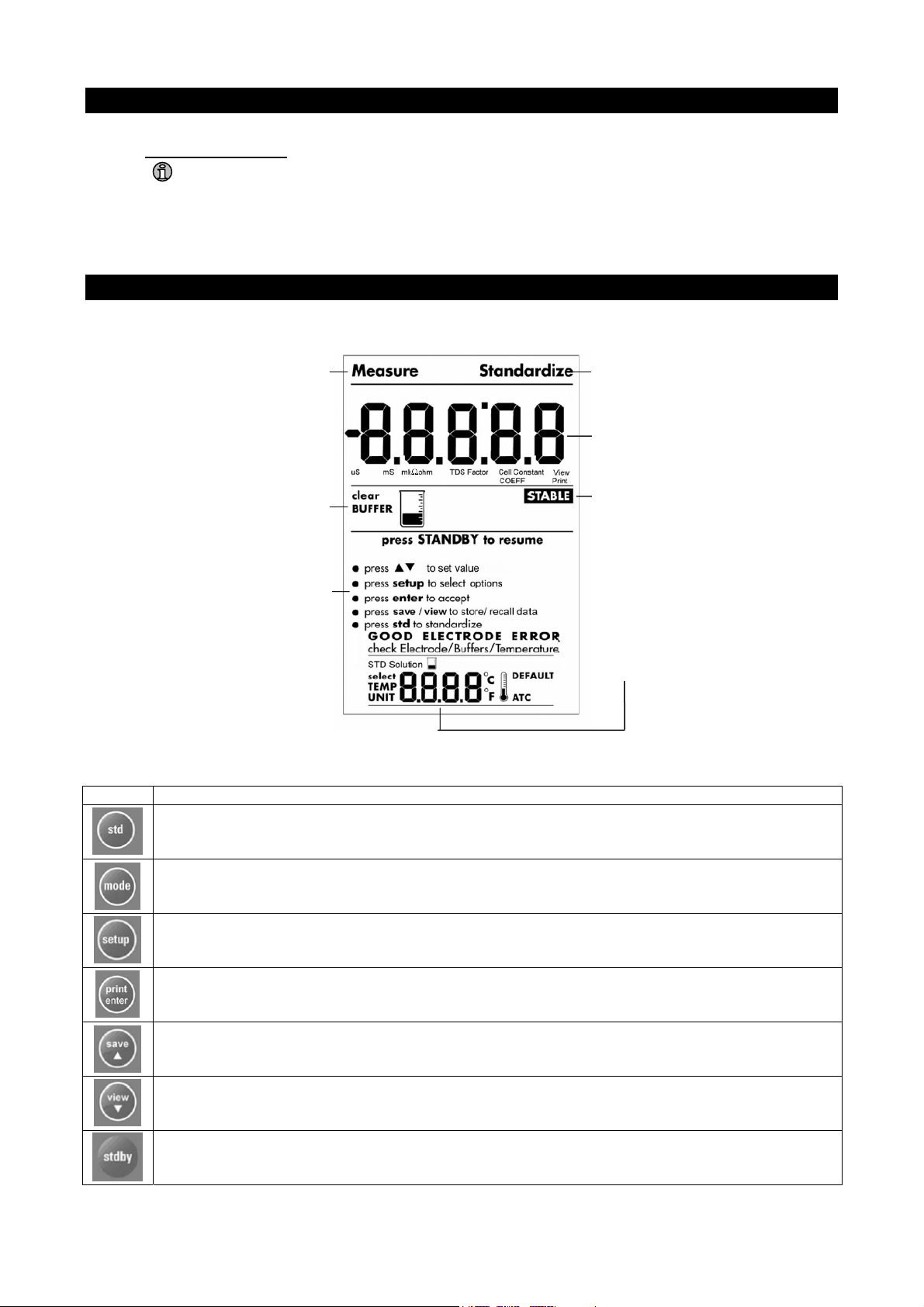
2.1 Display
Measurement
mode
Buffer
information
Calibration mode
Displays the Conductivity, TDS or
Resitivity value in measurement or
calibration mode
Stable icon
Prompts
Displays Temperature value
2.2 Keypad
KEY Function
Press to initiate standardisation or to exit and return to measurement without accepting the
calibration.
Press to select uS, kohm or TDS.
Press to access setup for configuration of meter setting.
PRINT: Press to print stored data from memory or current reading to a PC or printer (depending on
meter setup).
ENTER: Press to confirm selection or change being made.
Press to increment value or scroll up selection.
Press to store displayed data into memory
Press to decrement value or scroll down selection.
Press to recall and select memory location of stored data
Press to start up or put the meter in standby mode.
Page 4
3 PREPARATION
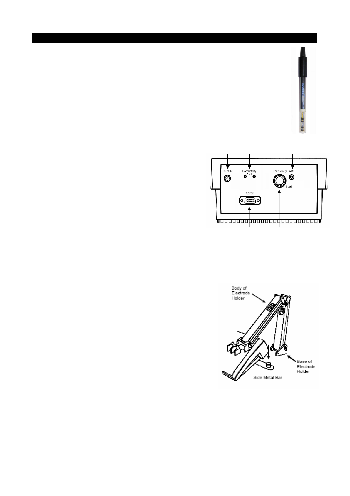
3.1 Conductivity Electrode Information
A 2-cell or 4-cell conductivity probe can be connected. Your meter includes a 4-Cell
conductivity electrode (Part No: EC620-165) with an electrode constant of K = 1.0. This
conductivity / TDS electrode features a built-in temperature sensor for Automatic
Temperature Compensation (ATC).
Prior to use, remove the protective cover from the end of the probe, soak the probe in
distilled or deionised water for 10 minutes. You may either:-
1. Connect the 2-cell probe by plugging its pin connectors into the dual pin sockets located
at the rear panel of the meter.
2. Connect the 4-cell probe by plugging its DIN connector into the DIN socket at the rear
panel of the meter.
3. Connect the ATC probe by plugging the 1/8” mini-phone jack into the ATC socket l
at the rear panel of the meter.
Note: DO NOT use both probes together (2 and 4 cell)
1.
ocated
2.
4-Cell Conductivity
probe EC620-165
3.
3.2 Connectors
The meter has 6 connectors:
1. Power connector (center negative)
2. 2-Cell conductivity connector
3. Temperature connector
4. RS232 connector
5. 4-Cell conductivity connector with built in Temperature
probe
CAUTION: Do not pull on the electrode cord to avoid internal
wire breakages.
4.
5.
3.3 Connecting the AC/DC Adapter
The AC/DC adapter must be unplugged. Ensure that main voltage matches the adapter. Slide the AC/DC
adapter jack into the socket marked POWER of the meter. AC/DC adapter specifications: Input Voltage: 110
or 220 V • Output Voltage: 12 VDC • Current: 500 mA.
NOTE: Ensure the input voltage matches your adapter before connection.
3.4 Connecting the Electrode Holder
This meter’s base plate has a side metal bar for a swivel electrode
holder. The holder can be mounted on either right or left side of the
meter.
To position the electrode arm:
Use a screwdriver to remove the screw holding the side bar. Line up
the side bar with the second screw slot. Use the earlier removed
screw to secure the side bar.
To install the electrode arm to the meter:
Align the slot of the arm with the metal rod at the metal side bar.
Push it down until it fully sits into position.
Page 5

4 CALIBRATION
4.1 Important Information on Meter Calibration
Your meter has four measuring ranges. You have an option of calibrating your meter in a single point
calibration for all the 4 ranges or for better accuracy; you can calibrate one point in each of the measuring
ranges (up to four points).
When you perform a
single point recalibration, the old calibration will be replaced by the new one even if the
new calibration is done in a different range from the old calibration. For example, if you have previously
calibrated at 1413 µS in 0 to 2000 µS range, and you recalibrate at 12.88 mS in 0 to 20.00 mS range, the
new calibration will override the previous calibration in 0 to 2000 uS range.
In the case of
multi point calibration, when you perform a multi point recalibration, old calibrations are
replaced only on a range basis. For example, if you previously calibrated at 1413 µS in 0 to 2000 µS range
and you recalibrate at 1500 µS (also in 0 to 2000 µS range), the meter will replace only the old calibration
data (1413µS) in that range. The meter will retain all calibration data in other ranges. To completely
recalibrate your meter, or when you use a replacement electrode, it is best to clear all calibration data.
The measuring ranges are:
Meter range symbol Conductivity range TDS range Resistivity range
r1 0 µS – 200.0 µS/cm 0 – 200.0 ppm 0 – 20.00 KΩ
r2 200.0 µS – 2.000 mS/cm 200.0 – 2000 ppm 20.00 – 200.0 KΩ
r3 2.000 mS – 20.00 mS/cm 2000 – 20000 ppm 200.0 KΩ – 2.000 MΩ
r4 20.00 mS – 500.0 mS/cm 20000 – 99999 ppm 2.000 – 100.0 MΩ
4.2 Preparing the Meter for Calibration
Before starting calibration, make sure you are in the correct measurement mode. For best results, select a
standard value close to the sample value you are measuring.
4.3 Temperature Calibration
Your electrode features a built-in temperature sensor which is factory calibrated. Calibrate your sensor only if
you suspect temperature errors may have occurred over a long period of time or if you have a replacement
electrode.
1. Connect the electrode.
2. Switch the meter on.
3. Press std.
4. Press mode to enter temperature calibration mode.
5. Dip the electrode into a solution of known temperature (i.e. a temperature bath). Allow
time for the built-in temperature sensor to stabilize.
6. Scroll with save/▲ or view/▼ to set the correct temperature value (i.e. the temperature
of the temperature bath). Maximum offset value is ±5.0 °C.
7. Press enter to confirm. The meter will be calibrated and return to measure mode.
Note: To exit without confirming the temperature calibration value, press std.
Note: Since temperature affects the accuracy of conductivity, TDS and Resistivity, it is recommended to
carry out a conductivity, TDS or Resistivity calibration after a temperature calibration is done.
4.4 Automatic or Manual, Single or Multi point Calibration (P5.0)
You can either choose automatic conductivity calibration or manual conductivity, TDS or Resistivity
calibration.
In the
automatic calibration mode, the meter automatically detects and verifies the appropriate known
calibration standards solutions before accepting these particular calibration standards as one of its
calibration values in a specific measurement range. The known calibration standards used for automatic
calibration are:
At 25.0°C : 84µS , 1413µS , 12.88mS , 111.8mS
At 20.0°C : 76µS , 1278µS , 11.67mS , 102.1mS
manual calibration, non-standard calibration values can be used. You can manually input the
In the
appropriate values as your desired calibration standards in each specific range.
Page 6

4.4.1 Selection of Automatic or Manual Calibration (P5.0)
Automatic calibration is applicable in conductivity measurement mode only, manual calibration is applicable
in conductivity, TDS and Resistivity mode. Only from the conductivity measurement
mode;
1. Press setup.
2. Press save/▲ or view/▼ until you view parameter P5.0 (ACAL).
3. Press enter
4. Press save/▲ or view/▼ to select. “YES” activates automatic calibration, “NO”
activates manual calibration.
5. Press enter to confirm or std to return to measurement mode.
4.4.2 Selection of Single or Multi Point Calibration (P5.0)
Single point calibration lets you have a single calibration factor for all 4 ranges by calibrating one point in
either one of the ranges, this factor is applied to all the ranges.
Multi point calibration gives better calibration accuracy by letting you calibrate in each of the 4 ranges, this
calibration factor would only be applicable in the particular range where the calibration is done.
1. Press setup
2. Press save/▲ or view/▼ until you view SPCAL. This will only be shown if setup is
entered from Resistivity or TDS mode. When setup is entered from the conductivity
mode you need to repeat step 1 to 5 from p 4.41 first.
3. Press enter
4. Press save/▲ or view/▼ to select. “YES” activates single point calibration, “NO”
activates multi point calibration.
5. Press enter to confirm or std to return to measurement mode.
4.5 Automatic Calibration (For Conductivity Calibration Only)
Standard buffer values: 84.0 uS/ 1.413 mS/ 12.88 mS/ 111.8 mS
This procedure describes the method for calibration to a 1413 µs calibration standard.
Note: select
Note: select
automatic or manual calibration as described in p 4.4.1
single -or multi point calibration as described in p 4.4.2
Note: To exit without confirmation, press std to go back to measurement mode.
1. If necessary, press mode to select conductivity mode.
2. Rinse the electrode with de-ionized water or a rinse solution, then rinse with a small
amount of calibration standard.
3. Dip the electrode into the calibration standard. Immerse the electrode tip beyond the
upper steel band. Stir the electrode gently to create a homogeneous sample. Allow
time for the reading to stabilize.
4. Press std to enter calibration mode. Standardize will appear in the upper corner of the display. The
primary display shows the current measured value, the secondary display shows the calibration standard
value.
5. Wait for Stable to appear
6. Press enter to confirm. The meter will now return to the measurement mode.
4.5.1 Multi point calibration
Repeat step 1 to 6 for every calibration point in each measuring range using the known calibration solutions
until all points have been calibrated.
4.6 Manual Calibration (For Conductivity, TDS & Resistivity Calibration)
This procedure describes calibration to a 1413 µs calibration standard.
Note: select
Note: select
automatic or manual calibration as described in p 4.4.1
single -or multi point calibration as described in p 4.4.2
Page 7

Note: To exit without confirmation, press std to go back to measurement mode.
Note: Ensure you set the correct TDS factor before TDS calibration.
1. Repeat step 1 to 4 from p 4.5. Both displays will show the current value.
2. Wait for the value to stabilize and press save/▲ or view/▼, adjust the value in the
upper display to the calibration standard used.
3. Press enter to confirm and return to measurement mode.
4.6.1 Multi point calibration
Repeat step 1 to 3 for every calibration point in each measuring range using the
calibration solutions until all points have been calibrated.
Note: If the standardisation is successful, the meter displays buffer icon in the middle part of the display in
the measurement mode.
4.7 TDS Calibration
4.7.1 Calibrating TDS with conductivity standards & adjusting TDS factor
Instead of calibrating for TDS directly using TDS calibration standard solutions, you can calibrate by using
the conductivity calibration method and enter the appropriate TDS conversion factor into the meter. For more
information regarding TDS Conversion Factor determination, please refer to our website:
www.eutechinst.com
4.7.2 Setting the TDS Conversion Factor (P6.0)
The factory default setting for TDS conversion factor is 0.5. If your
solution has a different TDS factor, you can improve accuracy by
setting the TDS factor prior to calibration.
1. Press mode to select TDS mode.
2. Press setup.
3. Press save/▲ or view/▼ until you view P6.0
4. Press enter.
5. Press save/▲ or view/▼ to select your calculated TDS conversion
factor.
6. Press enter to confirm and return to measurement mode or std to return to measurement mode.
4.7.3 Calibrating for TDS using TDS standards
After setting the correct TDS Factor, you can calibrate in the TDS mode.
1. Press mode to select the TDS mode.
2. Follow the instructions in p 4.6 for the rest of the calibration process, this time using the TDS calibration
standards.
Note: You can offset the TDS reading up to ± 40% from the default setting. If your measured value differs by
more than ± 40%, clean or replace electrode as needed.
Page 8

5 MEASUREMENT
5.1 Temperature Compensation
This meter can take measurements with automatic (ATC) or manual (MTC) temperature compensation (MTC
for 2-Cell electrode only). Factory default is ATC on. For ATC, attach the temperature electrode.
5.2 Taking Measurements
1. Rinse the electrode with de-ionized or distilled water before use. Shake or air dry. To avoid
contamination or dilution of your sample, rinse electrode with a small volume of your sample liquid.
2. Press stdby to switch on meter.
3. Dip the electrode into the sample. When dipping the electrode into the sample, ensure that the liquid
level is above its upper band. Stir the electrode gently in the sample to create a homogenous sample.
4. Allow time for the reading to stabilize.
5. Press mode to toggle between conductivity, TDS & Resistivity readings (if necessary).
5.3 Set the Stability Indicator (P8.0)
For activating or de-activating the stability indicator (STABLE icon appears when reading stabilises).
1. Press setup.
2. Press save/▲ or view/▼ until you view P8.0
3. Press enter to select.
4. Press save/▲ or view/▼ to select: “YES”, stable is on or “NO”, stable is off.
5. Press enter to confirm selection or std to return to measurement mode.
6 MEMORY FUNCTION
The meter stores up to 100 sets of data. Sets include conductivity, TDS, Resistivity and temperature.
6.1 Memory Input
Press save/▲ during measurement to input data into the memory. A memory location will appear for a
moment. If necessary, measure the next sample solution and press view/▼ key to input the next data into
the memory.
Note: If the memory is full the first value stored will be overwritten.
6.2 Memory Recall
1. Press view/▼ once to retrieve the last reading stored.
2. Press enter to recall the reading
3. Press enter to return to the next memory location screen.
4. Press save/▲ or view/▼ to scroll to a specific memory location, press enter to select.
5. Press std to exit Memory Recall.
Note: Readings stored in memory are retained even if the unit is turned off.
6.3 Clear Stored Data (P13.0)
Clears all stored data sets (from previous measurements) in the meter’s memory.
1. Press setup
2. Press save/▲ or view/▼ until you view P13.0.
3. Press enter
4. Press save/▲ or view/▼ to select: “YES”, to clear all data or “NO”, retains all data.
5. Press enter to confirm selection or std to return to measurement mode.
Note: After pressing enter to confirm the clearing of memory, “clear” will blink. Wait till it stops blinking
before proceeding with the next button press.
Page 9

7 COMMUNICATION / PRINT FUNCTION
7.1 Connecting the RS232C Cable
The meter provides an RS232C output for transmitting readings to a p
or computer via a cable. The output data is in the ASCII format. This for
rinter
mat
allows the data to be imported by a variety of software that reads ASCII
data (e.g. Microsoft’s Excel, Lotus, Quattro-pro etc.). A complimentar
Acquisition Software (DAS) is provided and it captures data transm
y Data
itted
into an ASCII file for later use.
1. Plug the RS232C connector into the RS232C port of the meter ensuring
the correct orientation.
2. Secure the RS232C connector by fastening the two screws at the side o
f
the male RS232C connector. The meter has an RS232 communication port for printing data to a printer or
computer. To use the meter directly with a printer, the printer should have either a 9 pin or a 25 pin RS
232C serial port.
7.2 Using the Meter with Printer or Computer
1. Insert CD-ROM containing Data Acquisition Software (DAS) into your CD-ROM drive and follow the
instructions on your screen.
2. Connect the meter with the RS232C cable to the computer.
3. Open the program on you computer, go to “File” and open “Communication settings” . The settings MUST
match the following parameters: a. Baud Rate: 9600 / b. Parity Bit: None / c. Stop Bit: 1 / d. Data Bit: 8 / e.
Flow Control: None
7.2.1 Set the Baud Rate( P9.0)
This setup page allows you to set the baud rate (bits per second).
1. Press setup
2. Press ▲/save or ▼/view until you view bAud.
3. Press enter
4. Press ▲/save or ▼/view to set the baud rate as 4800, 9600, 19200
or 38400 bps.
5. Press enter to confirm or std to exit from this page.
7.2.2 Set the Parity Bit (P10.0)
This setup page allows you to set the parity bit.
1. Press setup
2. Press ▲/save or ▼/view until you view PArit.
3. Press enter
4. Press ▲/save or ▼/view to select 0 (none), 1 (odd) or 2 (even).
5. Press enter to confirm or std to exit from this page.
7.2.3 Set the Stop Bit (P11.0)
This setup page allows you to set the stop bit of the communication
protocol interface.
1. Press setup
2. Press ▲/save or ▼/view until you view StOP.
3. Press enter
4. Press ▲/save or ▼/view to select 1 or 2.
5. Press enter to confirm or std to exit from this page.
7.3 Select Printing options (P12.0)
The meter can be set up to print:
• Current reading or
• All stored data.
Note : All the communication protocol for both the meter and computer/printer must match
before printing can be performed.
Page 10

1. Press setup
2. Press ▲/save or ▼/view until you view P12.0.
3. Press enter.
4. Press ▲/save or ▼/view to select Current or Memory data print out.
5. Press enter to confirm or std to exit from this page.
Note: All stored memory will remain in the meter after printing.
8 OTHER FUNCTIONS
8.1 Viewing Calibration & Electrode data (P1.0)
For viewing the calibrated buffer depending on the mode (Conductivity/ Resistivity/ TDS), the electrode type
(2-Cell/ 4-Cell), calibrated electrode cell constants and the calibrated buffer value.
1. Press setup.
2. Press save/▲ or view/▼ until you view parameter P1.0 (CAL).
3. Press enter repeatedly to view the effective Cell Constant and previous calibration data on each range
(r1, r2, r3 or r4).
4. When you have scrolled through all calibration data, you will automatically come to the screen shown
below. This screen displays the meter’s calibrated value.
5. Press enter to confirm or std to return to the measurement mode.
Note: If there is no calibration data at a particular point, the display will show “----“.
Note: Cell constants of electrode will degrade with time and usage. You can use this feature to prompt you
the need for a new probe prior to total failure. Recommended value as an indicator for a replacement of
probe is either 0.60 or 1.40 (±40% of 1.000).
Note: Entering the setup mode from Conductivity mode, calibration data will be in µS or mS. Entering the
setup mode from TDS mode, calibration data will be in ppm or ppt.
8.2 Clear User Calibration (P14.0)
Allows you to clear the user calibrated values for each measurement mode separately.
1. Press setup.
2. Press save/▲ or view/▼ until you view parameter P14.0.
3. Press enter.
4. Press save/▲ or view/▼ to select: NO retains current settings or YES clears all
calibrations and its data.
5. Press enter to confirm or std to return to measurement mode.
8.3 Selection of cell constant (P2.0)
The meter lets you select a cell constant of K = 0.1, 1.0 or 10. The cell included with your
meter has a cell constant of K=1.0.
1. Press setup.
2. Press save/▲ or view/▼until you view ‘2CEL’.
3. Press save/▲ or view/▼ to select the cell constant between K = 0.1, 1.0, or 10.
4. Press
enter to confirm selection and return to the subgroup menu.
5. Press std to return to measurement mode.
8.4 Setting the temperature coefficient (P3.0)
The temperature coefficient is the amount of change in conductivity per degree of
temperature; it is expressed in percent per °C. Entering the exact temperature coefficient
of your solution lets you accurately compensate temperature for almost any solution. You
can adjust 0.000 to 10.000 % per °C. Meter default is 2.100% per °C.
1. Press setup
Page 11

2. Press save/▲ or view/▼ until you view parameter P3.0.
3. Press enter to view the current temperature coefficient value.
4. Press save/▲ or view/▼ to select the temperature coefficient of your solution.
5. Press enter to confirm or std to return to the measurement mode.
8.5 Setting the normalisation temperature (P4.0)
Your meter will normalize its conductivity measurements to a standard temperature that
you can select. You can adjust the normalization temperature from 15°C to 30°C (59 to 86
°F). Meter default is 25.0°C (77 °F).
1. Press setup.
2. Press save/▲ or view/▼ until you view parameter P4.0. (“tnor”)
3. Press enter.
4. Press save/▲ or view/▼ to adjust the normalization temperature.
5. Press enter to confirm or std to return to measurement mode.
8.6 Selection of °C or °F (P7.0)
1. Press setup.
2. Press save/▲ or view/▼ until you view P7.0
3. Press enter.
4. Press save/▲ or view/▼ to select between °C and °F.
5. Press enter to confirm or std to return to measurement mode.
9 MAINTENANCE
9.1 Replatinisation of 2-Cell Electrode P15.0
Re-platinising the probe is only applicable for 2-cell probes. In this process the platinum on the surfaces of
the 2-cell probe are replaced.
Re-platinse when the cell constant changed by more than 50% from its typical value. Replatinisation takes
no more than 5 minutes.
9.1.1 Replatinisation procedure
1. Immerse the electrode in a suitable replatinising solution.
2. Press setup
3. Press save/
▲ or view/▼ until you view P15.0
4. Press save/▲ or view/▼ to select: “YES”, start procedure or “NO”, abort procedure.
5. Press enter to confirm or std to return to measurement mode.
6. Press save/▲ or view/▼, select “YES” to start replatinisation process, a timer will be shown.
7. Press enter to start the process, the timer will count down. After complete count down the meter will
return to measurement mode.
Note: Repeat step 2 if a longer replatinisation is required.
Note: A new cell constant must be established for the probe.
Page 12

9.2 Cleaning the meter
The meter requires no regular maintenance, but it is recommended to occasionally wipe down the front with
a damp cloth from time to time.
9.3 Electrode Care
1. Keep the electrode clean.
2. For best accuracy, soak a dry electrode for at least 5 to 10 minutes before calibration.
3. Rinse the electrode with de-ionized water before storing.
4. Never scratch the bands with a hard substance.
5. Do not strike the electrode against any hard surface.
6. Do not immerse the electrode in oily solutions.
7. Clean the electrode thoroughly by stirring it in a mild detergent bath or isopropyl alcohol. Wipe the
electrode with a soft tissue paper.
8. Recalibrate the meter after cleaning the electrode.
10 ERROR MESSAGES
Message Description
ERR. Error message for Conductivity Cal error.
Conductivity Reading > 500mS /
Or
Resistivity >100Mohm
TDS >99999 ppm
Ur Resistivity is short
-5.0°C/ 23.0°F When the temperature is under range
105°C/ 221.0°F When the temperature is under range
Err1 Communication error
 Loading...