

Page 1
Instruction Manual
gyM
sy...
gyM
sy...
24-hour Continuous
Field Monitors
pH, ORP, and Conductivity
68X254901
Technol o
Technol o
adeEa
adeEa
68X254901
Rev. 5 08/03
Rev. 5 08/03
Page 2

Preface
This manual serves to explain the use for all models of the Field Monitors for pH,
ORP, and Conductivity (each model sold separately). If there are doubts in the use
of this meter, please do not hesitate to contact the Authorized Distributor.
Eutech Instruments/ Oakton Instruments cannot accept any responsibility for damage
or malfunction to the meter caused by improper use of the instrument.
The information presented in this manual is subject to change without notice as
improvements are made, and does not represent a commitment on the part of Eutech
Instruments Pte Ltd/ Oakton Instruments.
Note: Eutech Instruments Pte Ltd/ Oakton Instruments reserves the right to
make improvements in design, construction, and appearance of our products
without notice.
Copyright © 2002 All rights reserved.
Eutech Instruments Pte Ltd
Oakton Instruments
Rev.5 08/03
Page 3

TABLE OF CONTENTS
1 INTRODUCTION..........................................................................................................................................1
2 FRONT PANEL.............................................................................................................................................1
2.1 KEYS FOR PH MONITOR ............................................................................................................................1
2.2 KEYS FOR ORP MONITOR ........................................................................................................................1
2.3 KEYS FOR CONDUCTIVITY MONITOR .......................................................................................................1
3 CONNECTING THE PROBE......................................................................................................................2
3.1 TO CONNECT THE PH OR ORP PROBE:.......................................................................................................2
4 PH CALIBRATION.......................................................................................................................................3
4.1 IMPORTANT INFORMATION ON PH MONITOR CALIBRATION......................................................................3
4.2 PH CALIBRATION ......................................................................................................................................4
5 ORP CALIBRATION....................................................................................................................................5
5.1 IMPORTANT INFORMATION ON ORP MONITOR CALIBRATION...................................................................5
5.2 ORP CALIBRATION ...................................................................................................................................6
6 CONDUCTIVITY CALIBRATION.............................................................................................................7
6.1 IMPORTANT INFORMATION ON CONDUCTIVITY/TDS MONITOR CALIBRATION .........................................7
6.2 CONDUCTIVITY CALIBRATION ..................................................................................................................8
7 MONITORING..............................................................................................................................................9
8 ELECTRODE CARE AND MAINTENANCE ...........................................................................................9
8.1 PH/ORP ELECTRODE STORAGE .................................................................................................................9
8.2 PH/ORP ELECTRODE CLEANING..............................................................................................................10
8.3 CONDUCTIVITY ELECTRODE....................................................................................................................10
9 TROUBLE-SHOOTING GUIDE...............................................................................................................10
10 ERROR MESSAGES...............................................................................................................................11
11 SPECIFICATIONS..................................................................................................................................12
12 METERS AND ACCESSORIES............................................................................................................13
13 WARRANTY............................................................................................................................................15
14 RETURN OF ITEMS...............................................................................................................................15
Page 4
1 INTRODUCTION
Thank you for purchasing this pH, ORP, or Conductivity Field Monitor.
The Field Monitor Series feature microprocessor technology, which gives it many
reliable, user-friendly features. These monitors were designed for long-term lowmaintenance use. Just plug in the AC adapter, calibrate and the unit is ready for
continuous monitoring. No batteries required.
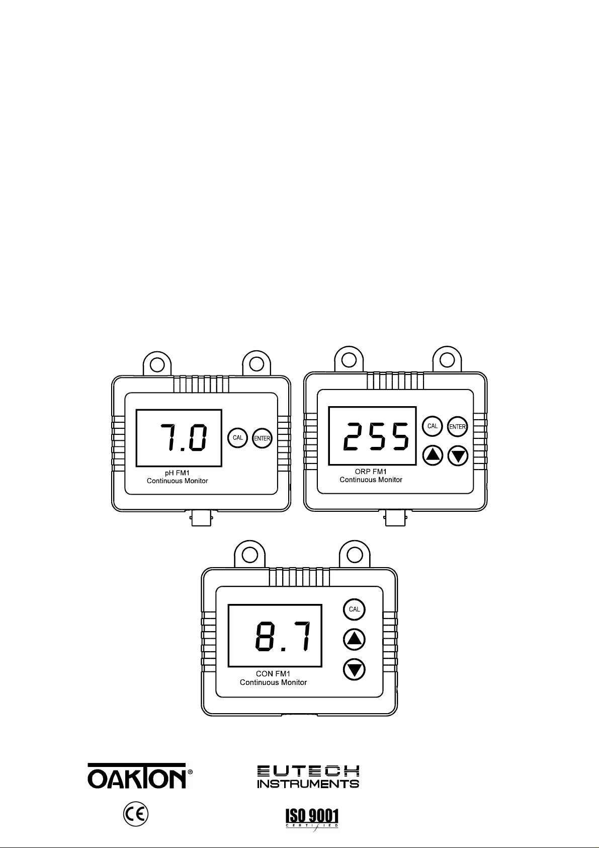
2 FRONT PANEL
The front panel consists of a 3-digit LED display, 2 keys for the pH Monitor, 4 keys for
the ORP Monitor, and 3 keys for the Conductivity Monitor.
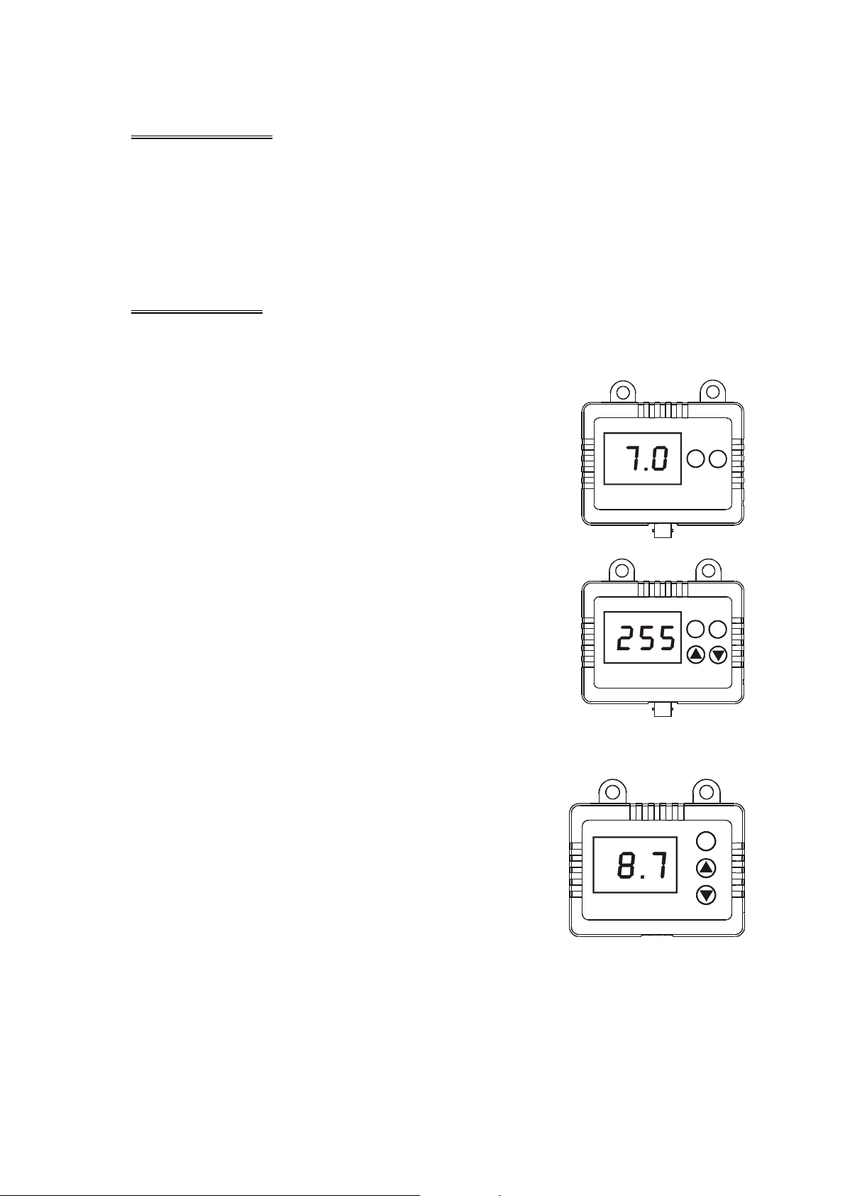
2.1 Keys for pH Monitor
CAL The CAL key switches monitor into calibration mode
from measurement mode. In calibration mode CAL
switches monitor back to measurement mode. See
page 3 for details.
ENTER Press the ENTER key to confirm the calibration while
in calibration mode.
pH FM1
Continuous Monitor
CAL
ENTER
2.2 Keys for ORP Monitor
CAL The CAL key switches monitor into calibration mode
from measurement mode. In calibration mode CAL
switches monitor back to measurement mode. See
page 5 for details.
ENTER Press the ENTER key to confirm the calibration while
in calibration mode.
ORP FM1
S
The S Up/Increment key scrolls value up in
Continuous Monitor
calibration mode.
T
The T Down/Decrement key scrolls value down in
calibration mode.
2.3 Keys for Conductivity Monitor
CAL The CAL key switches monitor into calibration mode
from measurement mode. In the calibration mode,
pushing CAL key confirms the calibration value and
returns to measurement mode. See page 7 for details.
S
The S Up/Increment key scrolls value up in
calibration mode.
T
The T Down/Decrement key scrolls value down in
calibration mode.
CON FM1
Continuous Monitor
Pressing S and T together while in calibration mode
switches the monitor back to measurement mode from calibration mode.
CAL
ENTER
CAL
1
Page 5
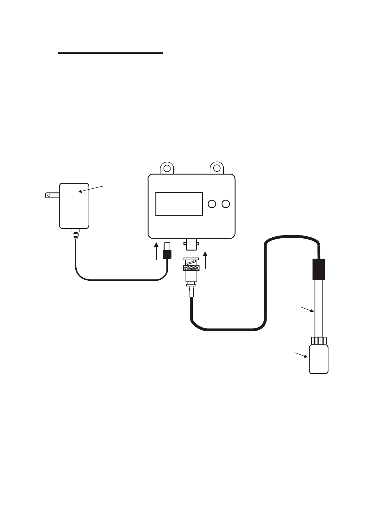
3 CONNECTING THE PROBE
The pH or ORP monitor uses any standard pH or ORP electrode with a BNC
connector. The probe for the Conductivity monitor is hard-wired into the unit, no
connection is necessary.
NOTE: Keep connector dry and clean. Do not touch connector with soiled hands.
3.1 To connect the pH or ORP probe:
Slide the BNC connector of the probe over the BNC connector socket on the monitor.
Make sure the slots of the connector are in line with the posts of the socket. Rotate
and push the connector clockwise until it locks. See Figure 1.
Power
Adapter
CAL
ENTER
7.0
pH FM1
Continuous Monitor
Push in the po w er
adapter plug to
connect the power supp ly
Push in the BNC
connector and turn
to tighten it.
Protection bottle for pH electrode
pH Electrode
Figure 1 - Connection diagram for Field Monitor
To remove probe, push and rotate the connector counter-clockwise. While holding
onto the metal part of the connector, pull probe away from the meter.
CAUTION: Do not pull on the probe cord or the probe wires might disconnect.
2
Page 6

4 pH CALIBRATION
This section is applicable for the following models:
• Eutech Instruments: EC-PHFM1ST11 & EC-PHFM1ST21
• Oakton Instruments: 35623-00, and -05 only
4.1 Important Information on pH Monitor Calibration
This monitor has 3 pH calibration points: 4, 7 and 10 with automatic buffer
recognition. For best accuracy, calibrate to all 3 pH points close to the temperature of
the solution you will be monitoring, starting with pH 7. We recommend that you
perform at least a 2-point calibration—at pH 7 first followed by pH 4 or pH 10
depending on the range of the operation. You can also perform a 1-point calibration,
but make sure that the buffer value is close to the sample value you are measuring.
Calibration should be performed regularly to ensure accuracy. Frequency of
calibration will vary and should be checked regularly until the required schedule has
been determined.
Be sure to remove the protective electrode storage bottle or rubber cap of the probe
before calibration or measurement. If the electrode has been stored dry, wet the
probe in tap water for 10 minutes before calibrating or taking readings to saturate the
pH electrode surface and minimize drift.
Do not reuse buffer solutions after calibration. Contaminants in the solution can affect
the calibration, and eventually the accuracy of the measurements.
.
NOTE: All new calibration data will over-ride existing calibration data.
3
Page 7

4.2 pH Calibration
1. Plug in the pH monitor to turn on. The monitor will
be in pH measurement mode.
2. Rinse the probe thoroughly with de-ionized water or
a rinse solution. Do not wipe the probe; this causes
a build-up of electro-static charge on the glass
surface.
3. Dip the probe into the calibration buffer pH 7. The
end of the probe must be completely immersed into
the sample. Stir the probe gently to create a
homogeneous sample.
4. Press the CAL key to enter the calibration mode.
"CA" will flash on the display for a second and then
a value close to pH 7.0 will flash.
5. Let the electrode soak in the buffer until reading is
stable, stirring occasionally (time will vary
depending on temperature and electrode
condition). When the display has flashed the same
pH value for 15 seconds or more, press the ENTER
key. "CO" will flash on the display. The reading
should now display pH 7.0. See Figure 2.
Immerse pH electrode into
buffer solution,
for example, pH 7
Press
Press
If necessary, repeat steps 2 through 5 for the
remainder of the buffer values (pH 4.0 and 10.0).
Figure 3 - pH
Calibration
4
Page 8

5 ORP CALIBRATION
This section is applicable for the following models:
• Eutech Instruments: EC-ORPFM1ST11 & EC-ORPFM1ST21
• Oakton Instruments: 35649-00 and -05 only
5.1 Important Information on ORP Monitor Calibration
Typically ORP measurements are taken on a relative basis and calibration is not
required. This monitor has ±100 mV offset adjustment, adjustable in 5 mV
increments. Choose a calibration standard that is close to your working condition.
Calibration should be performed regularly to ensure accuracy. Frequency of
calibration will vary and should be checked regularly until the required schedule has
been determined.
Be sure to remove the protective electrode storage bottle or rubber cap of the probe
before calibration or measurement. If the electrode has been stored dry, wet the
probe in tap water for 10 minutes before calibrating or taking readings to saturate the
ORP electrode surface and minimize drift.
Do not reuse calibration solutions after calibration. Dispose of any used calibration
solution. Contaminants in the solution can affect the calibration, and eventually the
accuracy of the measurements.
IMPORTANT: ORP offset adjustment is limited to ±100 mV from the original reading.
Adjustable in 5 mV increments.
NOTE: All new calibration data will over-ride existing calibration data.
5
Page 9

5.2 ORP Calibration
1. Plug in the ORP monitor to turn on. The monitor will
be in ORP measurement mode.
2. Rinse the probe thoroughly with de-ionized water or
a rinse solution. Do not wipe the probe; this causes
a build-up of electro-static charge on the surface.
3. Dip the probe into the calibration standard. The end
of the probe must be completely immersed into the
sample. Let probe soak 2 to 5 minutes or until
readings stabilizes.
4. Press the CAL key to enter the calibration mode.
"CA" will flash on the display for a second and then
a value close to the calibration standard will flash.
5. Press the S or T keys to adjust the display to
match the calibration standard value. Press the
ENTER key. "CO" will flash on the display. The
reading should now display the same value as the
calibration standard. See Figure 3.
Immerse ORP electrode into
a calibration standard solution,
for example, 255 mV
Press
Press
Press
Figure 5 - ORP
Calibration Procedure
6
Page 10

6 CONDUCTIVITY CALIBRATION
This section is applicable for the following models:
Description Eutech Instruments Oakton Instruments
Conductivity FMCON 1 with Conductivity
electrode and 110/120 VAC power adapter.
Conductivity FMCON 1 with Conductivity
electrode and 220/230 VAC power adapter.
Conductivity FMCON 2 with Conductivity
electrode and 110/120 VAC power adapter.
Conductivity FMCON 2 with Conductivity
electrode and 220/230 VAC power adapter.
Conductivity FMCON 3 with Conductivity
electrode and 110/120 VAC power adapter.
Conductivity FMCON 3 with Conductivity
electrode and 220/230 VAC power adapter.
EC-CONFM1ST11 35660-00
EC-CONFM1ST21 35660-05
EC-CONFM2ST11 35660-02~
EC-CONFM2ST21 35660-07~
EC-CONFM3ST11 35660-04~
EC-CONFM3ST21 35660-09~
6.1 Important Information on Conductivity/TDS Monitor Calibration
This monitor has ±30% adjustment. Adjustable in 0.1 mS increments. Choose a
calibration standard that is close to your working solution.
Calibration should be performed regularly to ensure accuracy. Frequency of
calibration will vary and should be checked regularly until the required schedule has
been determined.
Do not reuse calibration solutions after calibration. Dispose of any used calibration
solution. Contaminants in the solution can affect the calibration, and eventually the
accuracy of the measurements.
NOTE: All new calibration data will over-ride existing calibration data. Minimum
calibration value is 2.5 mS.
Adjustments and Minimum Calibration Value are according to specific conductivity
meter model:
Models Calibration Adjustments Minimum Calibration Value
FM CON 1 0.1 mS increments 2.5 mS
FM CON 2
FM CON 3
10 µS increments 250 µS
1 µS increments 37.5 µS
7
Page 11

6.2 Conductivity Calibration
1. Plug in the Conductivity monitor to turn on. The
monitor will be in conductivity measurement mode.
2. Rinse the probe thoroughly with de-ionized water or
a rinse solution, then rinse with a small amount of
calibration solution.
3. Dip the probe into the calibration solution. Immerse
the probe tip at least 2 cm into the solution. Stir the
probe gently to create a homogeneous sample.
4. Press the CAL key to enter the calibration mode.
"CA" will flash on the display for a second and then
a value close to the calibration standard will flash.
5. Press the S or T keys to adjust the display to
match the calibration standard value. Press the
CAL key. "CO" will flash on the display. The
reading should now display the same value as the
calibration standard. See Figure 4.
Immerse conductivity electrode
into a standard solution,
for example, 4 mS
Press
Press
Press
Figure 7 - Conductivity
Calibration Procedure
8
Page 12

7 MONITORING
Once the monitor is calibrated it is ready for monitoring. The monitor has two eyelet
holes. Mount the monitor where it can be easily viewed.
See figure below.
Mounting Eyelets
CAL
ENTER
pH FM1
Continuo us Monitor
8 ELECTRODE CARE AND MAINTENANCE
Since your pH/ORP electrode is susceptible to dirt and contamination, clean it every
one to three months depending on the extent and condition of use. Like batteries, a
pH/ORP electrode has limited life. Depending on the environment and the solution it
is immersed in, it may last from 6 to 12 months, or longer. Knowing when to change
your pH/ORP electrode usually comes after some experience. It is best to have
another pH/ORP tester such as pHScan/ pHTestr 1, Waterproof pHScan/ pHTestr
WP2, or ORPScan/ ORPTestr as reference.
8.1 pH/ORP electrode storage
For best results, always keep the pH/ORP bulb wet. Use the protective electrode
storage bottle filled with electrode storage solution (0.1M KCl) or pH 7 for overnight
and long term storage. DO NOT store in distilled water. The sensor should never be
stored dry. If left dry, soak in tap water or pH 7.0 buffer solution overnight.
9
Page 13

8.2 pH/ORP electrode cleaning
• Salt deposits: Dissolve the deposits by immersing the electrode in tap water for
ten to fifteen minutes. Then thoroughly rinse with distilled water.
• Oil/Grease film: Wash electrode pH/ORP bulb gently in some detergent and
water. Rinse electrode tip with distilled water or use a general-purpose electrode
cleaner (see ordering information).
• Clogged reference junction: Heat a diluted KCl solution to 60 to 80 C. Place the
sensing part of the electrode into the heated solution for about 10 minutes. Allow
the electrode to cool in some unheated KCl solution.
8.3 Conductivity electrode
For general cleaning, the use of deionized water will be sufficient. Rinse the
electrode thoroughly in the deionized water. After cleaning, wipe the electrode dry.
Never touch the metal sensors.
For intensive cleaning, when the electrode is contaminated, wash it carefully with a
mild detergent, after which wash thoroughly with deionized water. Always ensure
that there are no blockages of the electrode cavity. If there is, use a gentle jet of
water to dislodge any particles that may have been stuck there.
9 TROUBLE-SHOOTING GUIDE
Problem Cause Solution
No display a). Power adapter is not
connected properly or is
faulty.
Unstable
readings
a). Air bubbles in probe.
b). Dirty probe.
c). Probe not deep enough
in sample.
d). External noise pickup or
induction caused by
nearby electric motor.
a). Check that power adapter and
its wire are in place and
making good contact.
b). Check power supply.
a). Tap probe to remove bubbles.
b). Clean the probe and re-
calibrate.
c). Make sure sample entirely
covers the probe sensors.
d). Move or switch off interfering
motor.
No response a). Broken probe. a). Replace probe
Slow response a). Dirty / Oily probe. a). Clean probe. See “Electrode
Care & Maintenance” section.
10
Page 14

10 ERROR MESSAGES
pH
When pH value is
more than 14.0 pH
When pH value is
less than 0.0 pH
Displays when there
is an error in
calibration.
ORP
When ORP value is
more than 995 mV.
Conductivity
When Conductivity
value is more than
10.0 mS.
When ORP value is
less than 0 mV
When Conductivity
value is less than 0
mS.
Displays when there
is an error in
calibration.
11
Page 15

11 SPECIFICATIONS
Conductivity SPECIFICATIONS pH ORP
FM
CON1
Range 0.0 to 14.0 pH 0 to 995 mV 0 to 10.0
mS
Accuracy ± 0.1 pH ± 5 mV ±0.2
mS/cm
Resolution 0.1 pH 5 mV 0.1
mS/cm
Calibration Up to 3 points;
pH 4.0, 7.0 & 10.0
Automatic Buffer Recognition Yes
Automatic Temperature
Compensation
Operating Temperature 0 to 50 °C (0 to 120 °F)
Inputs BNC BNC Permanently wired
Display 3-digit LED (Red)
Environmental Requirements Operating: 0 to 50 °C (0 to 120 °F)
Power Requirements AC / DC Adapter 9 V, 200 mA
Dimension / Weight Meter: 19 x 10 x 6 cm; 80 g
Yes
Humidity Limits: 10 to 95% RH (non condensing)
Single- point,
Offset ± 100 mV
Storage: - 10 to 60 °C (14 to 140°F)
Boxed: 24 x 23 x 7 cm; 550 g
FM
CON2
0.0 to
990 µS
±20
µS/cm
10
µS/cm
Single- point,
± 30% full scale
FM
CON3
0.0 to
150 µS
±2
µS/cm
1 µS/cm
12
Page 16

12 METERS AND ACCESSORIES
Meters
Item Eutech Instruments
pH Field Monitor with pH electrode , 1 Strip of 10 pH
7 buffer tablets and 110/120 VAC power adapter.
pH Field Monitor with pH electrode , 1 Strip of 10 pH
7 buffer tablets and 220/230 VAC power adapter.
ORP Field Monitor with ORP electrode and 110/120
VAC power adapter.
ORP Field Monitor with ORP electrode and 220/230
VAC power adapter.
Conductivity FMCON 1 with Conductivity electrode
and 110/120 VAC power adapter.
Conductivity FMCON 1 with Conductivity electrode
and 220/230 VAC power adapter.
Conductivity FMCON 2 with Conductivity electrode
and 110/120 VAC power adapter.
Conductivity FMCON 2 with Conductivity electrode
and 220/230 VAC power adapter.
Oakton Instruments
Ordering Code
EC-PHFM1ST11 35623-00
EC-PHFM1ST21 35623-05
EC-ORPFM1ST11 35649-00
EC-ORPFM1ST21 35649-05
EC-CONFM1ST11 35606-00
EC-CONFM1ST21 35606-05
EC-CONFM2ST11 35660-02
EC-CONFM2ST21 35660-07
Ordering Code
Conductivity FMCON 3 with Conductivity electrode
and 110/120 VAC power adapter.
Conductivity FMCON 3 with Conductivity electrode
and 220/230 VAC power adapter.
EC-CONFM3ST11 35660-04
EC-CONFM3ST21 35660-09
Electrodes and Accessories
General Purpose, Epoxy-body double junction pH
Combination Electrode, 12x146 mm, 1-m cable
length
General Purpose Epoxy-body double junction ORP
Electrode, 12x146 mm, 1-m cable length
110/120 VAC Power Adapter (50/60 Hz) 2-pin type EC-120-ADA 35615-07
220/230 VAC Power Adapter (50/60 Hz) 2-pin type EC-220-ADA 35615-08
EC-FE72522-01B 35641-51
EC-FE79602-01B 35649-51
13
Page 17

Calibration Solutions
Item Eutech Instruments
Ordering Code
pH 4.01 buffer solution, 480 ml bottle (1 pint) EC-BU-4BT 00654-00
pH 7.00 buffer solution, 480 ml bottle (1 pint) EC-BU-7BT
pH 10.01 buffer solution, 480 ml bottle (1 pint) EC-BU-10BT
pH 4.01 buffer sachets, 20 ml x 20 pcs. EC-BU-4BS
pH 7.00 buffer sachets, 20 ml x 20 pcs. EC-BU-7BS
pH 10.01 buffer sachets, 20 ml x 20 pcs. EC-BU-10BS
12.88 mS KCl Calibration Solution in 480-ml leak-
proof bottle (1 pint)
2,764 µS KCl Calibration Solution in 480-ml leak-
proof bottle (1 pint)
10 µS conductivity standard sachet, 20 ml x 20 pcs
447 µS Conductivity Sachets (20 units x 20 ml per
box)
1,413 µS Conductivity Sachets(20 units x 20 ml per
box)
2,764 µS Conductivity Sachets(20 units x 20 ml per
box)
EC-CON-1288BT 00606-10
EC-CON-2764BT 00653-20
EC-CON-10BS
EC-CON-447BS 35653-10
EC-CON-1413BS 35653-11
EC-CON-2764BS 35653-12
Oakton Instruments
Ordering Code
00654-04
00654-08
35653-01
35653-02
35653-03
35653-09
15,000 µS Conductivity Sachets(20 units x 20 ml per
box)
EC-CON-15000BS 35653-13
14
Page 18

13 WARRANTY
The Field Monitor series is supplied with a 1-year warranty from manufacturing
defects and electrodes for 6 months from the date of purchase unless otherwise
stated.
If repair or adjustment is necessary and has not been the result of abuse or misuse
within the designated period, please return – freight pre-paid – and correction will be
made without charge. Eutech Instruments/ Oakton Instruments will determine if the
product problem is due to deviations or customer misuse.
Out of warranty products will be repaired on a charged basis.
Exclusions
The warranty on your instrument shall not apply to defects resulting from:
• Improper or inadequate maintenance by customer
• Unauthorized modification or misuse
• Operation outside of the environment specifications of the products
14 RETURN OF ITEMS
Authorization must be obtained from our Customer Service Department or authorized
distributor before returning items for any reason. A “Return Goods Authorization”
(RGA) form is available through our Authorized Distributor. Please include data
regarding the reason the items are to be returned. For your protection, items must be
carefully packed to prevent damage in shipment and insured against possible
damage or loss. Eutech Instruments/ Oakton Instruments will not be responsible for
damage resulting from careless or insufficient packing. A restocking charge will be
made on all unauthorized returns.
NOTE: Eutech Instruments Pte Ltd/ Oakton Instruments reserves the right to make
improvements in design, construction, and appearance of products without notice.
15
Page 19

For more information on Eutech Instruments/ Oakton Instruments’ products, contact your
nearest distributor or visit our website listed below:
Oakton Instruments
P.O Box 5136,
Vernon Hills, IL 60061, USA
Tel: (1) 888-462-5866
Fax: (1) 847-327247-2984
E-mail: info@4oakton.com
Web-sites:
www.4oakton.com
Eutech Instruments Pte Ltd
Blk 55, Ayer Rajah Crescent,
#04-16/24 Singapore 139949
Tel: (65) 6778 6876
Fax: (65) 6773 0836
E-mail: marketing@eutechinst.com
Web-site: www.eutechinst.com
Distributed by:
 Loading...