

Page 1
gyM
y..
.
Instruction Manual
DO 6
Economy Hand-held Dissolved Oxygen Meter
68X243622
Rev 0 01/04
Technol o
adeEas
Page 2

Preface
This manual serves to explain the use of the Dissolved Oxygen palm-top meter
DO 6.
This manual functions in two ways: first as a step by step guide to help you
operate the meter; second, it serves as a handy reference guide.
This manual is written to cover as many anticipated applications of the DO6
palm-top meter as possible. If there are doubts in the use of the Dissolved
Oxygen palm-top meters, please do not hesitate to contact the nearest Eutech
Instruments / Oakton Instruments authorized Distributor.
Eutech Instruments/Oakton Instruments will not accept any responsibility for
damage or malfunction to the meter caused by improper use of the instrument.
The information presented in this manual is subject to change without notice as
improvements are made, and does not represent a commitment on the part of
Eutech Instruments / Oakton Instruments.
Copyright © 2004
Eutech Instruments Pte Ltd
Oakton Instruments
All rights reserved.
Rev 0, 01/04
Page 3

TABLE OF CONTENTS
1 INTRODUCTION......................................................................1
2 DISPLAY & KEYPAD FUNCTIONS......................................2
2.1 DISPLAY................................................................................2
2.2 KEYPAD ................................................................................3
3 PREPARATION.........................................................................4
3.1 INSERTING & REMOVING RUBBER BOOT ..............................4
3.2 INSERTING THE BATTERIES ...................................................5
3.3 BATTERY REPLACEMENT ......................................................6
3.4 DISSOLVED OXYGEN PROBE INFORMATION ..........................7
3.5 CONNECTING THE PROBE TO METER .....................................9
3.6 SWITCHING THE METER ON ................................................10
3.7 MEASUREMENT MODE SELECTION:- PERCENTAGE
SATURATION (%), CONCENTRATION (MG/L)(PPM) AND
TEMPERATURE(T) ...........................................................................11
4 CALIBRATION.......................................................................12
4.1 IMPORTANT INFORMATION ON METER CALIBRATION .........12
4.2 PREPARING THE METER FOR CALIBRATION.........................13
4.3 TEMPERATURE CALIBRATION .............................................15
4.4 DISSOLVED OXYGEN CALIBRATION IN % SATURATION ......17
4.4.1 To calibrate 100% Saturation:...................................17
4.4.2 To calibrate 0% Saturation........................................19
4.5 DISSOLVED OXYGEN CALIBRATION IN MG/L OR PPM
CONCENTRATION MODE
...................................................................20
4.5.1 To calibrate in mg/L (ppm) Concentration mode:......20
5 MEASUREMENT....................................................................22
5.1 WITH AUTOMATIC TEMPERATURE COMPENSATION (ATC) 22
5.2 MANUAL TEMPERATURE COMPENSATION...........................23
Page 4

5.3 TAKING MEASUREMENTS....................................................25
5.3.1 To take measurements:...............................................25
5.4 TAKING PRESSURE/SALINITY COMPENSATED DO
MEASUREMENTS .............................................................................26
5.4.1 Pressure Setting Adjustment.......................................26
5.4.2 Salinity Setting Adjustment .........................................29
6 HOLD FUNCTION..................................................................30
7 ADVANCED SETUP FUNCTIONS.......................................31
7.1 ADVANCED SETUP OVERVIEW ............................................31
7.1.1 To enter the % Saturation or Temperature Set Up
menu: ....................................................................................31
7.1.2 To enter the mg/L (ppm) Concentration Set Up menu:...
....................................................................................31
7.2 (COF.1) CONFIGURATION MENU ........................................36
7.2.1 Selection of Automatic Temperature Compensation ..36
7.2.2 Selection of mg/L or ppm mode..................................38
7.3 (CAL.2) CALIBRATION DATA .............................................39
7.3.1 Viewing the % Saturation calibration data................39
7.3.2 Viewing the mg/L (ppm) Concentration calibration
data ....................................................................................39
7.4 (ELE.3) ELECTRODE PROPERTIES .......................................40
7.4.1 Viewing the electrode Slope Factor............................40
7.4.2 Viewing the % Saturation Offset (Only available in %
Saturation or Temperature Set Up menu): .................................40
7.4.3 Viewing the 100% Saturation mV value.....................41
7.4.4 Viewing the 0% Saturation mV value.........................41
7.5 (ATO.4) AUTOMATIC OFF ...................................................43
7.6 (RST.5) RESET TO FACTORY DEFAULT ................................44
7.6.1 Calibration Reset........................................................44
7.6.2 User Reset...................................................................46
7.7 (OFS.6) % SATURATION OFFSET ADJUSTMENT ..................47
7.8 (DPR.7) DISSOLVED OXYGEN PARAMETERS .......................49
Page 5

7.8.1 Pressure Setting Adjustment.......................................49
7.8.2 Salinity Setting Adjustment .........................................51
8 PROBE CARE AND MAINTENANCE.................................52
8.1 PROBE CARE .......................................................................53
8.2 PRE-MEMBRANED CAPS REPLACEMENT .............................53
8.3 TO REPLACE THE PROBE PRE-MEMBRANED CAP...................54
8.4 ELECTROLYTE SOLUTION ....................................................55
9 TROUBLE-SHOOTING GUIDE...........................................56
10 ERROR MESSAGES...........................................................57
11 FACTORY DEFAULT SETTINGS...................................58
12 SPECIFICATIONS..............................................................60
13 ACCESSORIES....................................................................62
14 ADDITIONAL INFORMATION.......................................63
14.1 DISSOLVED OXYGEN ...........................................................63
14.1.1 General Information...................................................63
14.1.2 Measurement Units.....................................................65
14.1.3 What Is Being Measured? ..........................................65
14.1.4 Air Calibration...........................................................66
14.1.5 Applications................................................................66
15 WARRANTY........................................................................ 68
16 RETURN OF ITEMS...........................................................69
Page 6

Instruction Manual DO 6
1 INTRODUCTION
Thank you for purchasing the DO 6 Dissolved Oxygen palm-top meter. This
economy microprocessor-based palm-top meter has a large custom LCD
(Liquid Crystal Display) for clear and easy reading.
The DO 6 offers the measurement of dissolved oxygen in the percentage
saturation mode and in the concentration mode. Temperature measurement is
also available in degrees Celsius. The meter ensures accurate measurement of
the Dissolved Oxygen values through its temperature, barometric pressure and
salinity compensation features.
Your meter includes a dissolved oxygen probe, refill solution, a rubber boot, 4
alkaline “AAA” batteries, and instruction manual.
Please read this manual thoroughly before operating your meter.
To order other accessories and standard solutions, please refer to the Section
on Accessories for more information.
1
Page 7
Instruction Manual DO 6
r
2 DISPLAY & KEYPAD FUNCTIONS
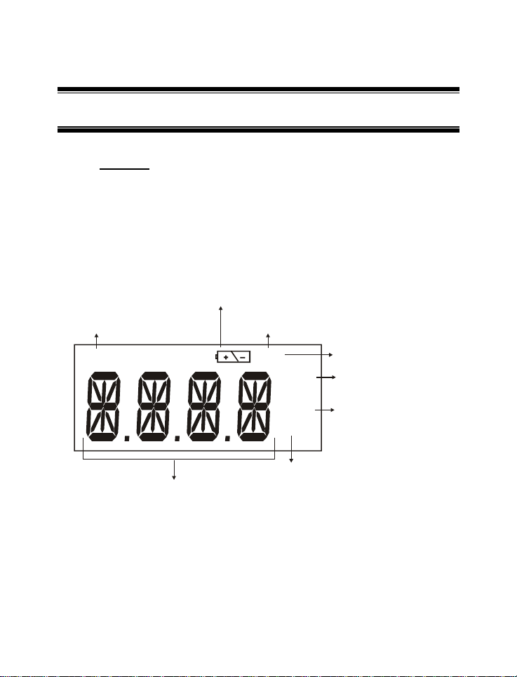
2.1 Display
The meter has a large custom LCD that consists of 14-segment 4 digit display
and operation annunciators for Percentage Saturation measurement mode (%),
Concentration measurement mode (mg/L or ppm) and Temperature
measurement mode in degrees Celsius (T). Other annunciators include “A”
(when the ATC function is activated), “CAL” (when meter is in calibration mode)
and battery diagram for low battery condition. See Figure 1.
Calibration Mode
Low Battery annunciato
Annunciator
CAL
14-segment Liquid Crystal Display
Figure 1: Active LCD display for DO 6
Temperature Mode
TA
mg/l
ppm
%
Percentage
(Percentage Saturation
Mode)
2
A T C annunciator
milligram per litre
(Concentration Mode)
parts per million
Page 8
Instruction Manual DO 6
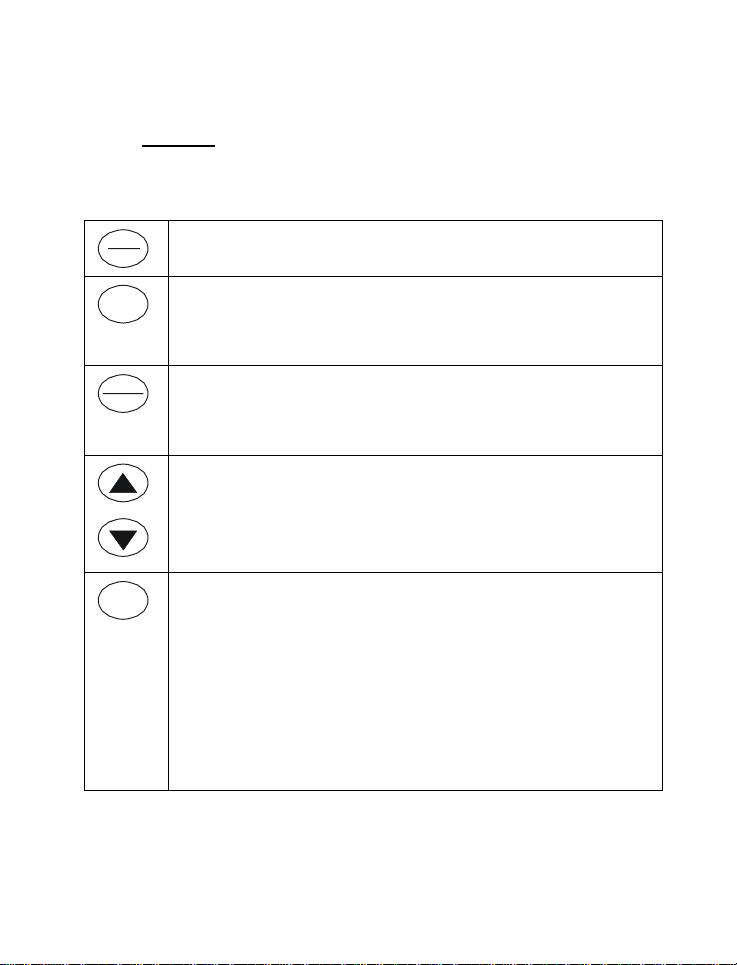
2.2 Keypad
The DO 6 meter has 6 keys on its splash-proof keypad; ON/OFF,
HOLD/ENTER CAL, MODE, ▲ and ▼ keys. Some buttons have several
functions depending on its mode of operation.
ON
OFF
CAL
HOLD
ENTER
MODE
ON/OFF – Powers on and shuts off the meter. The meter will start in the
measurement mode it was in when last switched off.
CAL – Activates the calibration mode for Percentage Saturation,
Concentration and Temperature calibrations.
Deactivates calibration or setup without confirming a value in calibration
mode.
HOLD -Activates/Deactivates freezing of the measured reading while in
measurement mode.
ENTER - Confirms the calibration values in Calibration mode and the
selections in the SETUP menu.
▲▼ – Sets the calibration values during the Concentration and
Temperature calibration.
Scrolls through each SETUP and its sub group menu.
Set offset adjustments and configuration settings.
MODE - Selects the measurement option between DO Percentage
Saturation measurement; DO Concentration measurement and
Temperature measurement.
When pressed together with ON/OFF key during power on, SETUP
mode is selected. This menu allows meter customization with
preferences such as activating ATC selection, DO concentration
measurement unit selection, viewing of the last calibration data,
viewing of the electrode properties, selecting the auto power off,
resetting calibration data or meter settings back to factory default,
setting the offset adjustments, setting barometric pressure in Hg or
PA for barometric pressure compensation and setting of the salinity
value for salinity compensation.
3
Page 9
Instruction Manual DO 6
3 PREPARATION
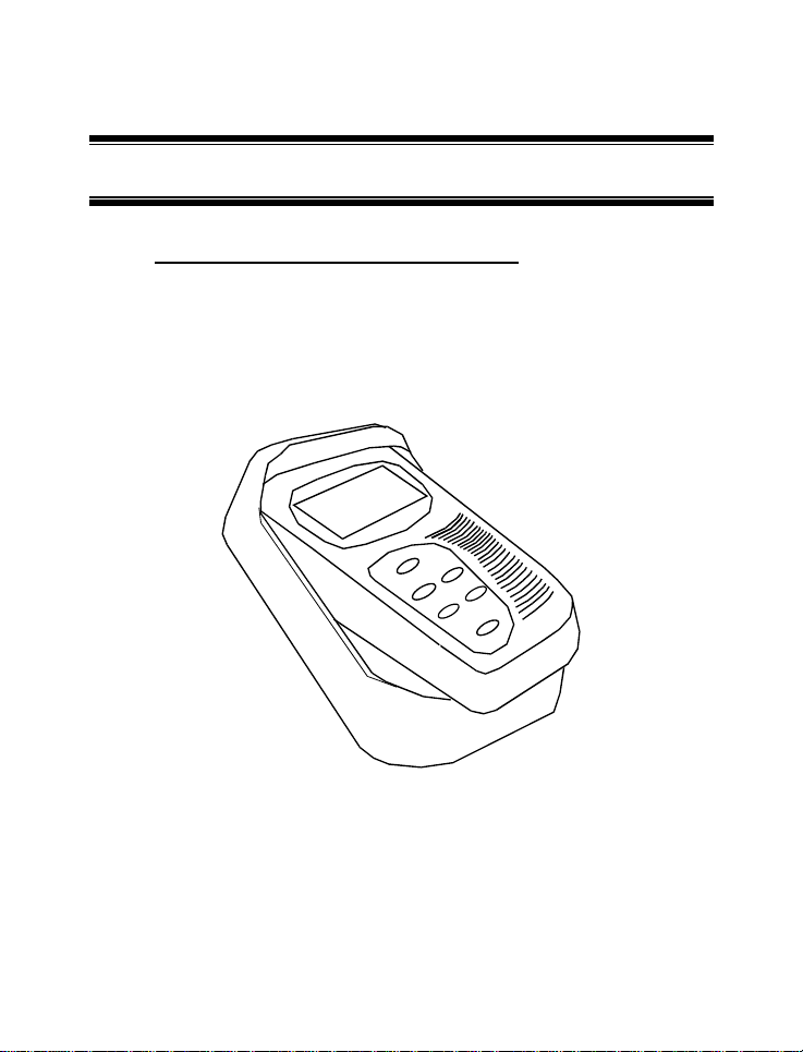
3.1 Inserting & Removing Rubber Boot
1) To remove meter from rubber boot, push out from the bottom edges of
meter until it is completely out of boot. Ensure that the cables of Dissolved
Oxygen electrode or temperature probe are not connected.
2) To insert meter into rubber boot, slide in from the top of meter before
pushing the bottom edges of meter down to set it into position. Lift up the
stand at the back of meter for bench top applications if necessary.
Figure 2: Inserting or removing the rubber boot
4
Page 10
Instruction Manual DO 6
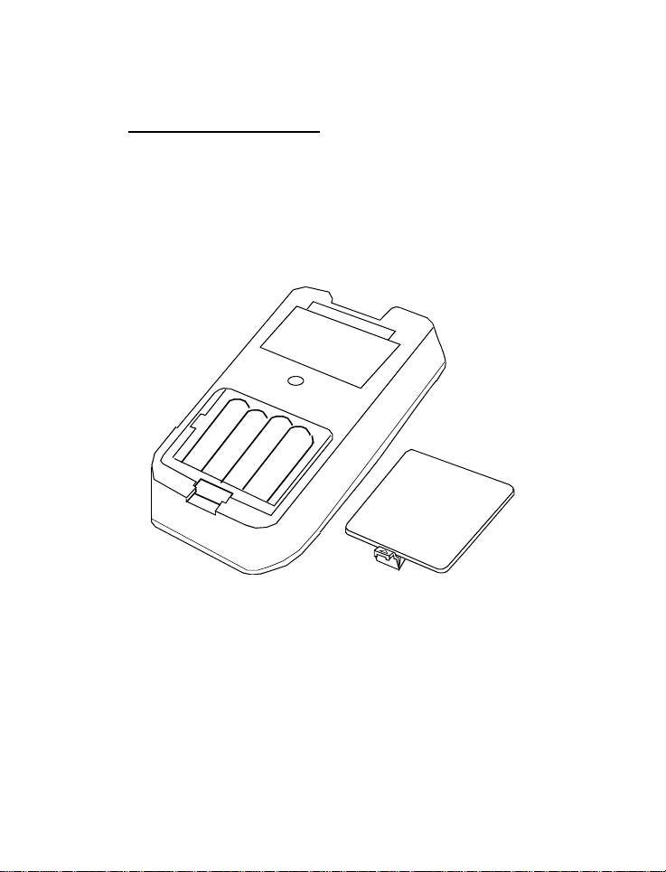
3.2 Inserting the Batteries
The battery compartment is found at the back of instrument as shown in Figure
3. To open the battery compartment first remove protective rubber boot/stand
then:
1) Push in the direction of arrow and lift up the cover.
2) Note the polarity of battery before inserting into position.
3) After replacement, place cover back and press down until it locks tight.
Figure 3: Inserting the batteries
5
Page 11
Instruction Manual DO 6
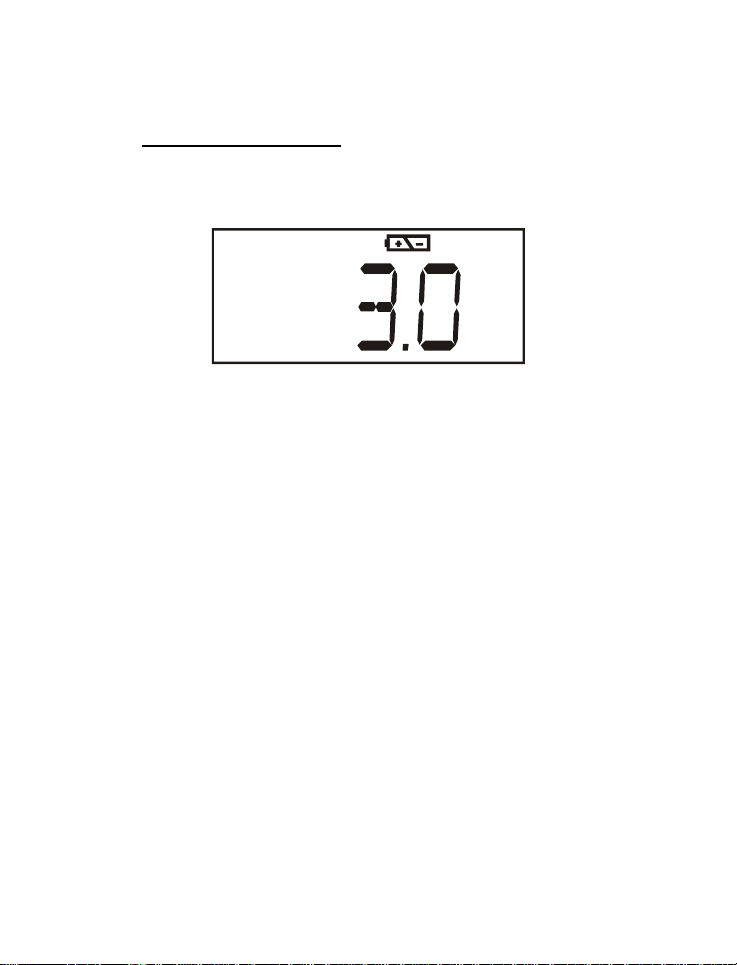
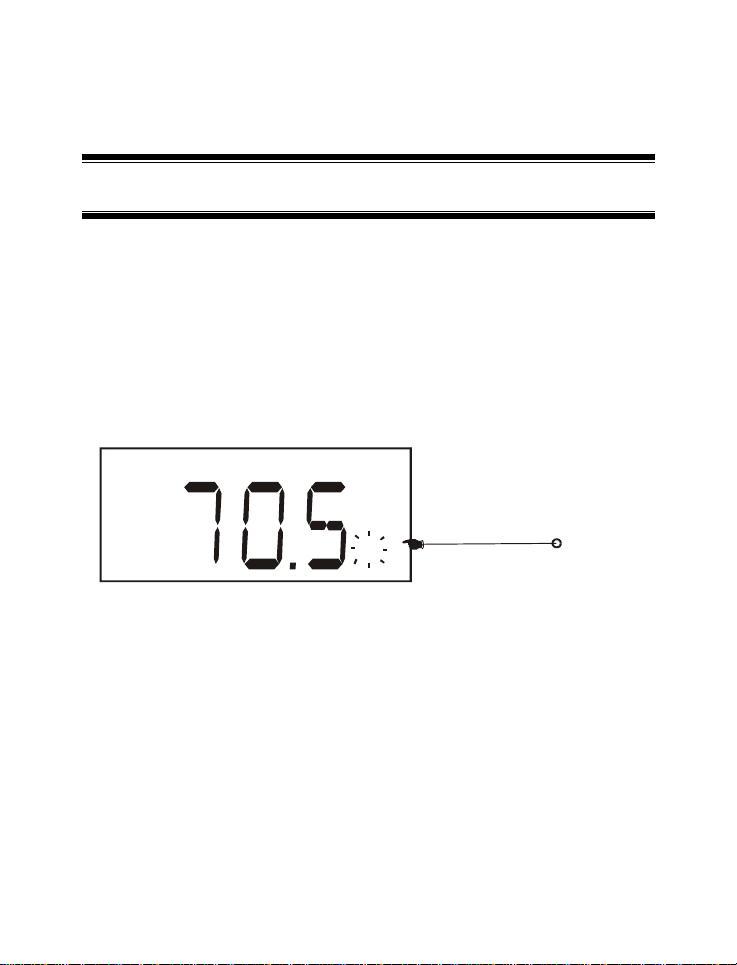
3.3 Battery Replacement
A low battery annunciator in the LCD alerts you when battery power is running
low. See Figure 4. Replace with the same type as recommended by the
manufacturer.
%
Figure 4: Low Battery Condition
Caution: Power off the meter when changing battery.
6
Page 12
Instruction Manual DO 6
3.4 Dissolved Oxygen Probe Information
The DO 6 palm top meter is supplied with a
Dissolved Oxygen Probe that works on galvanic
principle, that is, it does not require any
polarising voltage from your meter. Rather it will
generate a millivolt signal proportional to the
amount of oxygen in the solution.
Your DO Probe has a twin cable, one with a
BNC connector for the DO measurement input,
and the other with a phono jack plug for the
temperature measurement input. Its sensing
area consists of a cathode, anode, and an inner
electrolyte which is separated from your sample
solution by an oxygen permeable membrane
pre-membraned to the probe’s detachable cap.
Re conditioning of your probe is made easy with
the introduction of this specially designed
detachable pre-membraned cap.
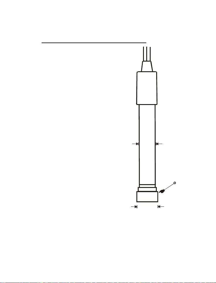
This light weight probe (93X233912 /35642-50)
has a built-in temperature sensor for Automatic
Temperature Compensation (ATC) with 12mm
diameter epoxy body housing and 16 mm
diameter Noryl detachable cap. Its compact
sensing area reduces air entrapment which
makes it easy to obtain fast, accurate and
stable readings. Simply stir the probe in the
solution being measured. Shaking will aid to
remove bubbles if needed before taking a
reading. Also, always ensure to remove water
drops from the membrane when calibrating in
air.
Proper use of probe is essential to ensure that
the optimum measurement is taken in a short
12 mm
16 mm
Figure 5: 12 mm Galvanic DO
probe (93X233912 / 35642-50)
Detachable
Pre-membraned Cap
(Probe Sensing Area)
7
Page 13

Instruction Manual DO 6
time. Always immerse the probe beyond the pre-membraned cap. The minimum
water flow rate is 2 inch/second across membrane. The temperature range for
use is within 0 to 50 °C.
Always ensure that the probe’s membrane is protected against any scratches or
dents. The whole pre-membraned cap has to be replaced if the membrane is
damaged. It is also important to keep the membrane clean so as to produce an
optimum and accurate measurement.
See Section 8 - “Probe Care and Maintenance” for more information.
8
Page 14
Instruction Manual DO 6
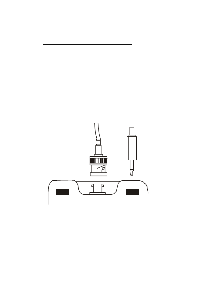
3.5 Connecting the Probe to Meter
1) Insert the BNC connector from the electrode to the BNC connector socket
on the meter accordingly and rotate connector clockwise until it locks. See
Figure below.
2) To remove, simply rotate the connector in counter-clockwise direction until
it unlocks, and slide the connector off the socket.
3) Plug the phono jack of temperature sensor into the phono socket of the
meter as shown in Figure below.
Caution: Do not pull or force the probe cord or the probe wires might
disconnect.
Note: Keep connectors clean. Do not touch connector with soiled hands.
BNC Connector for
DO probe
Figure 6: DO 6 probe to meter connections
Phono jack for
Temperature probe
9
Page 15
Instruction Manual DO 6
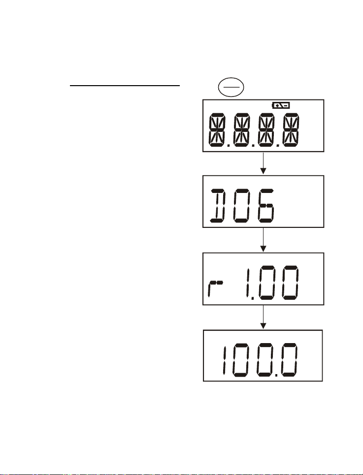
3.6 Switching the Meter On
When switching the meter on, it will go
through a series of display, eventually
showing the revision number of the meter
before going to the measurement mode.
The mode of measurement which the
meter displays will be similar to the last
measurement mode to which the meter is
switched off.
Press ON/OFF key to power up your
meter.
1) All LCD segments will light up for 1.5
seconds.
2) The display will then momentarily
show the meter’s identification “DO 6”
with the annunciators for percentage
saturation mode and concentration
mode.
3) The display continues to switch to
display meter’s revision number for
1.5 seconds before finally showing
the measurement mode.
4) Either percentage saturation
measurement mode, concentration
measurement mode or temperature
measurement mode will be displayed
following the previous measurement
mode to which the meter is switched
off.
ON
OFF
CAL 13 CAL 24
TAvg
mg/l
NTU
ppm
%pH
mg/l
ppm
%
A
%
10
Figure 7: Power Up sequence
Page 16
Instruction Manual DO 6
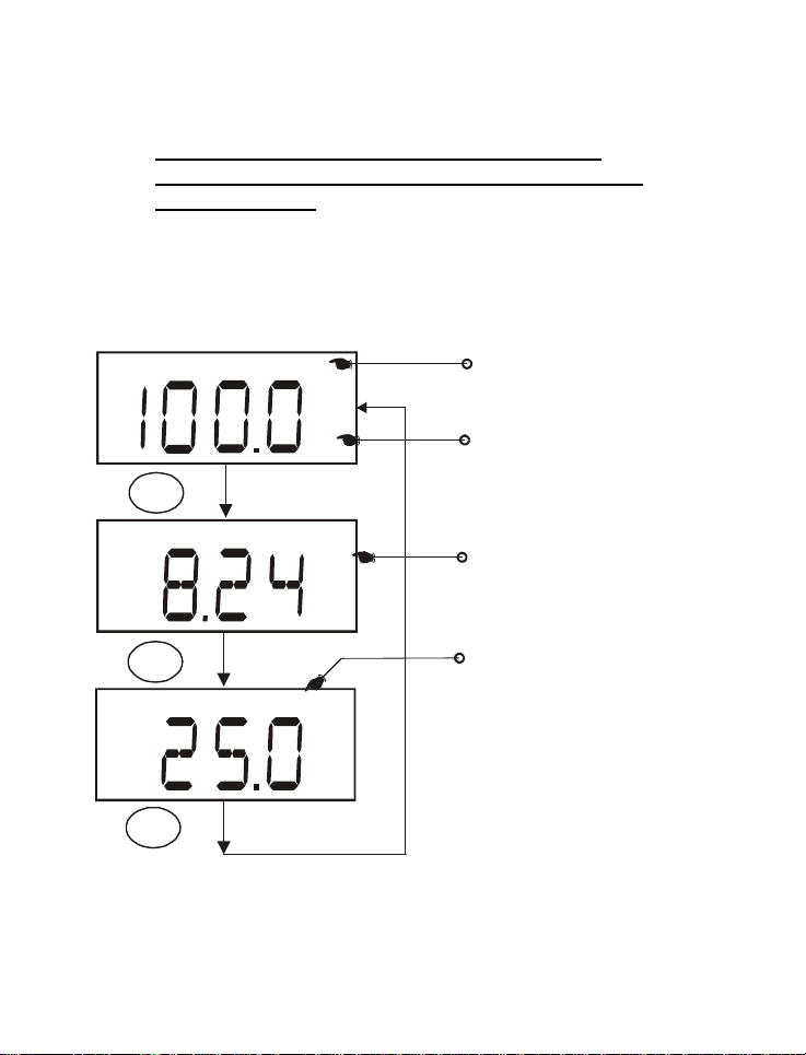
3.7 Measurement Mode Selection:- Percentage
Saturation (%), Concentration (mg/L)(ppm) and
Temperature(T)
By simply pressing the MODE key, you can select the measurement mode of
percentage saturation measurement, concentration measurement or
temperature measurement.
The customized annunciator shall indicate the selection of the measurement
mode.
A
%
MODE
A
mg/l
Automatic Temperature
Compensation
Percentage Saturation
Concentration Mode
MODE
MODE
TA
Temperature Mode
Figure 8: Measurement mode selection using the mode key
11
Page 17
Instruction Manual DO 6
4 CALIBRATION
4.1 Important Information on Meter Calibration
Your meter has three measurement modes namely the DO % saturation
measurement mode, the DO mg/L (ppm) concentration mode and the
Temperature measurement mode.
Since the mg/L (ppm) concentration value of dissolved oxygen varies with
temperature, barometric pressure and salinity, the meter with its electrode has
to be calibrated with consideration to these factors to ensure a proper
measurement. Therefore, it is very important to set the proper temperature,
barometric pressure and salinity values in the meter prior to any calibration or
measurement process. Since the dissolved oxygen measurements in %
saturation will linearly affect the mg/L (ppm) concentration measurement, it is
important that the meter has to be first calibrated in the % Saturation mode and
temperature mode before commencing the mg/L (ppm) concentration mode
calibration.
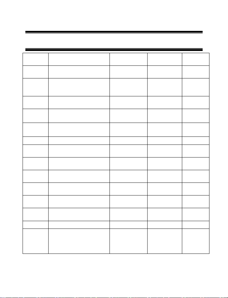
In % saturation calibration mode, the dissolved oxygen calibration values will
vary according to the barometric pressure correction set in the meter. Therefore
it is necessary to set the barometric pressure first before proceeding to %
Saturation calibration. The following table is an example which explains the
acceptance calibration values when % Saturation mode calibration is attempted
under different absolute value and under two different barometric pressures.
% Saturation factory
default value
Acceptance Calibration Value
(760mmHg)
Acceptance Calibration Value
(700mmHg)
less than 10% 0% 0%
10.1% to 49.9% Err.1 (error 1) Err.1 (error 1)
50% to 200% 100% 92.1%
12
Page 18

Instruction Manual DO 6
In the mg/L (ppm) concentration calibration mode, barometric pressure, salinity
and temperature of the calibration sample needs to be set in the meter prior to
calibration. Since the pressure has already been set in the % saturation
calibration which is done earlier and assuming that the calibration is done on
the same barometric pressure and if you are using the temperature sensor in
automatic temperature compensation mode, you only need to input the known
salinity of the calibration sample to the meter. The dissolved oxygen mg/L (ppm)
concentration value can then be calibrated to the known sample concentration
calibration value. Note that the concentration calibration window is +/- 40% of
the factory default value. However the minimum point of calibration is 2 mg/L.
When you recalibrate your meter in % saturation mode, old calibrations in %
saturation will be replaced while the % saturation offset adjustment will be
erased. However, recalibration in the mg/L (ppm) concentration mode will only
replace the old calibration in the concentration mode and do not affect the
calibration in the percentage saturation mode.
To completely recalibrate your meter, or when you use a replacement electrode,
it is best to clear all calibration data. To erase all the old calibration data
completely, see Section 7.6 (rSt.5) Reset to Factory Default
4.2 Preparing the Meter for Calibration
Before starting calibration, make sure you are in the correct measurement mode
and in the correct calibration sequence. The temperature and the % Saturation
calibration must be done first before attempting to do the mg/L (ppm)
Concentration calibration.
In % Saturation, the meter is able to perform either a one point calibration or a 2
point calibration. For one point calibration, it is recommended that you perform a
100% Saturation calibration in saturated air. If you opt for 2 point calibration,
you can calibrate for 100% Saturation in saturated air and 0% Saturation using
a zero oxygen solution. The meter will take several minutes to reach 0%
Saturation value after submersion into the zero solution.
Rinse the probe well in the de-ionized (DI) water or rinse solution and wipe the
probe carefully taking care of the membrane.
Calibrate the meter in all the modes to ensure the highest accuracy throughout
the DO measurement range. In % Saturation calibration, should there be a
13
Page 19

Instruction Manual DO 6
calibration failure for 0% Saturation slope calibration; the meter may have
exceeded the limit of 10% of the factory calibrated absolute value. The sensor
may have to be re- conditioned. Also, note that the DO 6 meter will not perform
0% or 100% Saturation calibration for absolute value ranging from 10.1% to
49.9%. The meter also will not perform the mg/L (ppm) Concentration
calibration for an absolute value of less than 2.00 mg/L (ppm) or calibration
which is out of its window tolerance of +/- 40% from the factory default value.
An error message of “Err.1” will be indicated and will return the meter to the
measurement mode.
All new calibration values will automatically override the existing data. It is
recommended to calibrate the meter periodically and or if it is suspected to be
inaccurate.
Always rinse the probe with either DI water or rinse solution before and after
each calibration/sample measurement. When calibrating in air, make sure that
any water droplets from the probe’s membrane are removed.
For details please refer to Section 8 - PROBE CARE AND MAINTENANCE.
Note: The DO6 factory calibrated default value is in respect to 760mm Hg or
101.3 kPa barometric pressure (sea level). To set the barometric pressure to
different value, see Section 5.4.1 Pressure Setting Adjustment.
14
Page 20
Instruction Manual DO 6
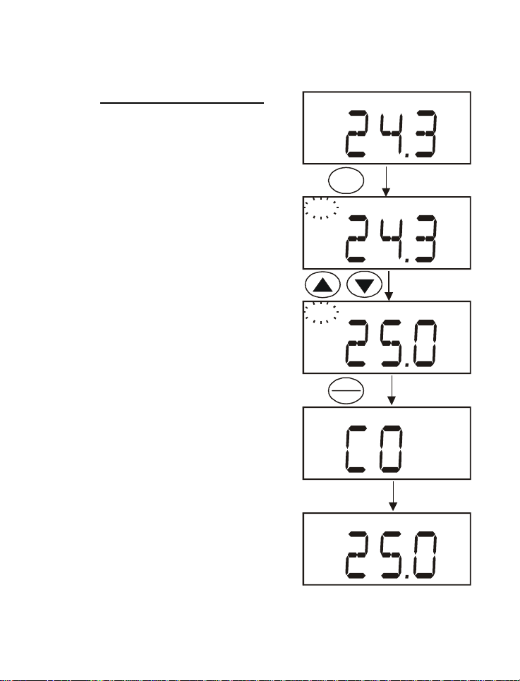
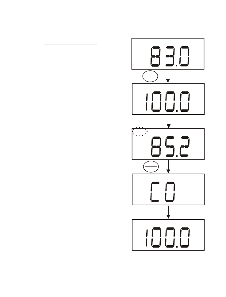
4.3 Temperature Calibration
DO mg/L (ppm) Concentration measurement
is dependent on the temperature of the
sample to be measured. Most users will
choose to have the DO6 automatically
compensate for temperature using the
temperature sensor that is built into the DO
probe. However, it is possible to manually
enter a known temperature to the meter
(manual temperature compensation). The
built-in temperature sensor of the DO6 probe
is factory calibrated. However, the
temperature can be re-calibrated if needed
and is recommended when a replacement
probe is used.
Before calibration, ensure that the meter
displays annunciator “A” to indicate that it is
in automatic temperature compensation
mode. Please see Set Up menu on page 36
for its activation procedure.
1) Switch the meter on. Press MODE to
select temperature mode. The display
should show the annunciator “T” for
temperature mode and “A” for automatic
temperature compensation mode.
2) Dip the probe to a solution of known
temperature (i.e. a temperature
bath).Allow some time for the reading to
stabilize.
3) Press the CAL key. The CAL indicator
will appear and blinks above the display.
The temperature value displayed is with
respect to the factory default calibration.
CAL
CAL
CAL
HOLD
ENTER
TTA
A
Factory default
Temperature
Measurement
TA
“CO” will display for
1.5 seconds
TA
15
Figure 9: Temperature Calibration Sequence
Page 21

Instruction Manual DO 6
4) Press the ▲ and ▼ keys to adjust the meter reading to the correct
temperature value (i.e. the temperature of the temperature bath)
5) Press the HOLD/ENTER key to confirm temperature calibration and return
to measurement mode.
NOTE:
To exit from Temperature Calibration mode without confirming the calibration,
press CAL instead of HOLD/ENTER.
Temperature calibration is restricted to ± 5°C from the factory default
temperature measurement displayed during calibration.
16
Page 22
Instruction Manual DO 6
4.4 Dissolved Oxygen
Calibration in % Saturation
You can calibrate this meter quickly and
easily in air. The exact calibration value
depends on barometric pressure. The meter
is set to a factory default of 760 mm Hg,
which results in a calibration value of 100%
Saturation in air.
NOTE: If the barometric pressure setting has
been changed from 760 mm Hg, the
calibration value in air will automatically
adjust to a value other than 100%. The
adjusted value will be correct for the new
barometric pressure setting.
See Section 5.4.1 Pressure Setting
Adjustment on page 26 to change the
pressure setting.
4.4.1 To calibrate 100% Saturation:
1) Rinse the probe well with DI water or
rinse solution. Do not touch the
membrane.
2) Press the MODE key to select the %
Saturation mode.
3) Hold the probe in the air with the sensor
facing downwards. Wait for the reading
to stabilize.
4) Press the CAL key. The display will
show the intended percentage
calibration point (100%) with a CAL
indicator at the top corner for 1.5
seconds. The CAL indicator will then
17
A
%
CAL
CAL
%
Calibration point will be
displayed for 1.5 seconds
CAL
%
HOLD
ENTER
A value with respect to the
factory default calibration
will be displayed
“CO” will dis play ed for
1.5 seconds
A
%
Figure 10: 100% Saturation Calibration
Page 23

Instruction Manual DO 6
blink and the display will show a value which is with respect to the factory
default calibration.
NOTES:
When calibration is attempted on a factory calibrated absolute value
measurement of 10.1% to 49.9%, the display will show the absolute value
measurement for 1.5 seconds before displaying Err.1 and goes to the
measurement mode.
5) Press the HOLD/ENTER key to confirm the calibration. The meter displays
“CO” for 1.5 seconds and automatically calibrates to 100.0% air saturation
and returns to measurement mode.
Note: You can offset your % DO calibration. See Section 7.7 (OFS.6) %
Saturation Offset Adjustment for directions.
18
Page 24

Instruction Manual DO 6
4.4.2 To calibrate 0% Saturation
1) Rinse the probe well with DI water or
rinse solution.
2) Press the MODE key to select the %
Saturation mode, if necessary.
3) Dip the probe into the zero oxygen
solution. Wait for the reading to
stabilize.
4) Press the CAL key. The display will
show the intended percentage
calibration point (0%) with a CAL
indicator at the top corner for 1.5
seconds. The CAL indicator will then
blink and the display will show a value
which is with respect to the factory
default calibration.
Note: When calibration is attempted on a
factory calibrated absolute value
measurement of 10.1% to 49.9%, the
display will show the absolute value
measurement for 1.5 seconds before
displaying Err.1 and goes to the
measurement mode.
5) Press the HOLD/ENTER key to
confirm the calibration. The meter
displays “CO” for 1.5 seconds and
automatically calibrates to 0.0%
Saturation and returns to
measurement mode.
CAL
CAL
CAL
HOLD
ENTER
A
%
%
Calibration point will be
displayed for 1.5 seconds
%
A value with respect to the
factory default calibration
will be displayed
“CO” will display ed for
1.5 seconds
A
Figure 11: 0% Saturation Calibration
19
%
Page 25

Instruction Manual DO 6
4.5 Dissolved Oxygen
Calibration in mg/L or
ppm concentration mode
Calibrating the meter to 100% Saturation
will also calibrate the concentration mode
at the value in mg/L corresponding to
100% Saturation. This should produce
acceptable results in most applications.
This meter also lets you make a calibration
adjustment in mg/L (ppm) Concentration
mode without affecting your % Saturation
calibration.
To select between mg/L and ppm units,
see page 38, “Selection of mg/L or ppm
mode”.
4.5.1 To calibrate in mg/L (ppm)
Concentration mode:
1) Calibrate 100% Saturation as per
Section 4.4.
2) Rinse the probe well with DI water or
rinse solution. Wipe the outside of the
probe carefully (do not touch the
membrane).
3) Dip the probe into a sample of known
oxygen concentration. Wait for the
reading to stabilize.
4) Press the MODE key to select the
mg/L (ppm) Concentration mode.
5) Press the CAL key. The display will
show a value which is with respect to
20
A
mg/l
CAL
CAL
CAL
HOLD
ENTER
A value with respect to the
factory default calibration
will be displayed
“CO” will display
for 1.5 seconds
mg/l
mg/l
A
mg/l
Figure 12: mg/L (ppm)
Concentration Calibration Sequence
Page 26

Instruction Manual DO 6
the factory default calibration with a CAL indicator blinking at the corner of
the display.
6) Press the ▲ and ▼ keys to adjust the reading to the known oxygen
concentration of the sample.
7) Press the HOLD/ENTER key to confirm the calibration. The meter will
display “CO” for 1.5 seconds and automatically calibrates to the value you
have entered and returns to the measurement mode.
NOTES: The concentration calibration window is +/- 40% of the factory default
value. However, the minimum point of calibration is 2 mg/L. In an event where
the default measured value is less than 2 mg/L and a calibration is attempted,
the display will show “2.00” and then error message “Err.1” will be displayed
momentarily before returning to measurement mode.
You can change the barometric pressure value and salinity value in the mg/L
(ppm) Set Up menu (see Section 7.8.1 and 7.8.2 for Pressure Setting
Adjustment and Salinity Setting Adjustment). Please refer to page 23 if you are
intending to use manual temperature compensation.
21
Page 27
Instruction Manual DO 6
5 MEASUREMENT
The DO 6 meter is capable of taking measurements with automatic or manual
temperature compensation.
5.1 With Automatic Temperature Compensation (ATC)
For Automatic temperature compensation, make sure the phono jack of the
probe (see Figure 6 in Section 3.5) is securely inserted. The ATC annunciator
“A” will be blinking if the ATC probe is disconnected. Activate the “A.ATC” mode
in the set up menu, if necessary. See page 36.
A
Automatic Temperature
Compensation activated
%
Figure 13: Automatic Temperature Compensation
22
Page 28

Instruction Manual DO 6
5.2 Manual Temperature
Compensation
For manual temperature
compensation, simply deactivate the
“A.ATC” mode as explained in the set
up menu on page 36. The automatic
temperature compensation annunciator
“A” will not be displayed to represent
that the meter is in manual temperature
compensation mode.
To use manual temperature
compensation, you need to enter the
temperature value of your process into
the meter. You can select any
temperature between 0 and 50 °C.
Default value is 25 °C.
1) Switch on the meter and if
necessary, press MODE key to
select temperature measurement
mode.
2) Press CAL key to start temperature
calibration process.
3) The “CAL” indicator will start
blinking and the display will show
the last manual set temperature
value.
4) Check the temperature of your
sample using an accurate
reference thermometer. Wait for
the thermometer value to stabilize.
Press the ▲ or ▼ key of your
meter to manually set its
temperature value according to the
CAL
CAL
CAL
HOLD
ENTER
T
T
Last set manual
temperature setting
T
“CO” will display for 1.5
seconds
T
23
Figure 14: Manual Temperature
Compensation value selection sequence
Page 29

Instruction Manual DO 6
value of the reference thermometer used.
5) Press the HOLD/ENTER key to confirm the manual temperature setting
made. The “CO” indicator will appear for 1.5 seconds before the display
returns to the measurement mode.
24
Page 30

Instruction Manual DO 6
5.3 Taking Measurements
During measurement, care must be taken to ensure that the probe’s membrane
surface does not touch anything. Stir around the solution to prevent any air
bubbles from being trapped on the
membrane before taking a reading.
A
IMPORTANT: Since the DO probe
consumes oxygen from the sample, the
sample must constantly flow past the
%
membrane to achieve more accurate
readings. You can use a stirrer to
MODE
accomplish this.
A
5.3.1 To take measurements:
mg/l
1) Rinse the probe well with DI water or
rinse solution.
2) Select the appropriate measurement
mode. Press the MODE key to toggle
between modes:
MODE
TA
a. Percentage Saturation (%)
b. Concentration (mg/L) or (ppm)
c. Temperature (T)
3) Dip the probe into the sample. Stir the
solution gently to homogenize the
Figure 15: Measurement mode
sample. Make sure that the sample is
continuously flowing past the membrane sensor.
4) Take your measurements once your meter reading has stabilized.
Note: “Ur”/”Or” will be displayed if the instruments exceeds the specified
measuring range. See Section 12 for range specification.
To select between mg/L and ppm units, see Set Up menu on page 38.
25
Page 31

Instruction Manual DO 6
5.4 Taking Pressure/Salinity Compensated DO
Measurements
In taking pressure and salinity compensated DO measurements, the pressure
and salinity values of your measurements need to be adjusted from the Set Up
menu. The pressure setting adjustment feature is available when Set Up menu
is derived from the % Saturation mode, mg/L (ppm) Concentration mode or
Temperature mode. Salinity setting feature, on the other hand, will only be
available when Set Up menu is derived from the mg/L (ppm) Concentration
mode. See Section 7.1- Advanced Setup Overview for more information.
During measurement, the DO meter will automatically compensate for salinity
and pressure based on the values entered in the Set Up Menu. The meter is
factory set at 760 mm Hg (101.3 kPa) barometric pressure setting and a salinity
factor of 0.0 ppt.
5.4.1 Pressure Setting Adjustment
(See Figure 16 for flow chart explanation)
1) Switch off your meter in mg/L (ppm) Concentration mode.
2) While pressing and hold the MODE key, switch on the meter by pressing
the ON/OFF key.
3) Once the ON/OFF key is released, the meter will enter the Set Up menu by
displaying “SEt.P”. By releasing the MODE key, the display will show the
configuration menu “COF.1”. See section 7 – Advanced Setup Functions.
4) Press the ▲ and ▼ keys to scroll through the Set Up main group menu till
the display shows “DPr.7”.
5) Press the HOLD/ENTER key and the meter will enter the barometric
pressure units selection menu with the display showing one of two; either
“A.HG” for mm Hg or “A.PA” for kilo Pascal, depending on what the meter’s
last set up was.
6) Use the ▲ and ▼ keys to toggle between the two units of pressure
measurement and press the HOLD/ENTER key to confirm selection.
26
Page 32

Instruction Manual DO 6
7) Use the ▲ and ▼ keys to set the pressure value and press the
HOLD/ENTER to confirm the setting. A confirmation indicator “CO” will be
displayed for 1.5 seconds before the meter shows the next display of
Salinity setting “b.SAL”. If the Set Up menu is derived from other than the
mg/L (ppm) Concentration mode, the meter will return to the Set Up main
group menu “DPr.7”.
8) Press CAL key to return to measurement mode, or continue to make a
salinity setting adjustment.
27
Page 33
Instruction Manual DO 6
HOLD
ENTER
HOLD
ENTER
HOLD
ENTER
“CO” will display
Display will cont inue to
Salinity setting menu
“b.SAL” if Set Up menu is
entered from mg/l (ppm)
mode. Otherwise display will
return back to “DPr.7”
for 1.5 seconds
Figure 16: Pressure Setting Adjustment Sequence
HOLD
ENTER
HOLD
ENTER
“CO” will display
for 1.5 seconds
Display will cont inue to
Salinity setting menu
“b.SAL” if Set Up menu is
entered from mg/l (ppm)
mode. Otherwise display will
return back to “DPr.7”
28
Page 34
Instruction Manual DO 6
5.4.2 Salinity Setting Adjustment
NOTE: This mode is available only from
the mg/L (ppm) Concentration Set Up
menu.
1) Repeat steps 1 to 5 as in the steps of
Pressure Setting Adjustment.
HOLD
ENTER
2) Press the HOLD/ENTER key twice till
the meter displays the Salinity setting
mode “b.SAL”.
3) Press the HOLD/ENTER key to enter
the Salinity setting mode.
4) Use the ▲ and ▼ keys to enter the
salinity of your solution in parts per
thousand (ppt). Factory default is 0.0.
Salinity values up to 50 ppt can be
entered.
5) Press HOLD/ENTER key to confirm
the value. A confirmation indicator
“CO” will be displayed for 1.5 seconds
before returning to the main group
menu “DPr.7”.
HOLD
ENTER
6) Press CAL key to return to the
measurement mode.
“CO” will display for
1.5 seconds
Display will return back to “DPr.7”
subgroup menu
Figure 17: Salinity Setting Adjustment Sequence
29
Page 35
Instruction Manual DO 6
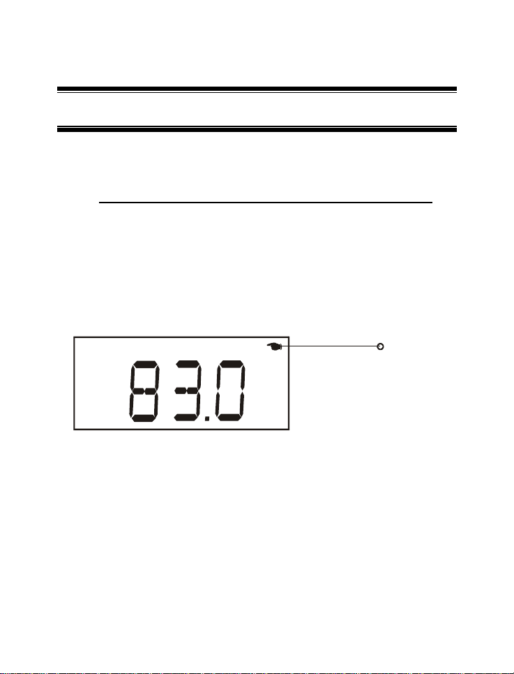
6 HOLD FUNCTION
This feature lets you freeze the display for a delayed observation. HOLD can be
used in any measurement mode.
1) To hold a measurement, press the HOLD/ENTER key while in
measurement mode. The %, mg/L, ppm or T annunciator in the display will
start blinking to indicate that the measurement is being held.
2) To release the held value, press the HOLD/ENTER again. The
annunciator will stop blinking to indicate that the held value has been
released.
3) Continue to take measurements.
A
%
Annunciator Blinks when
meter is in “HOLD” mode
Figure 18: Unit in HOLD mode
Note: This meter has a selectable auto off feature which when activated will
shut the meter off automatically after 20 minutes of non use.
If the meter is shut off either automatically or manually, the HOLD value will be
lost
30
Page 36

Instruction Manual DO 6
7 ADVANCED SETUP FUNCTIONS
7.1 Advanced Setup Overview
The advanced setup mode lets you customize your meter’s preferences and
defaults. There are two Set Up menus: - one which is derived from the %
Saturation or Temperature mode and the other is derived from the mg/L (ppm)
Concentration mode.
7.1.1 To enter the % Saturation or Temperature Set Up menu:
1) Make sure that the meter is switched-off while in the % Saturation or
Temperature measurement mode.
2) With the MODE key pressed, power the unit on by pressing the ON key.
Release the ON key before releasing the MODE key.
3) “SEt.P” indicator will appear momentarily and “COF.1” will appear next.
4) You are now in the % Saturation or Temperature Set Up menu.
7.1.2 To enter the mg/L (ppm) Concentration Set Up menu:
5) Switch off the meter in the mg/L (ppm) Concentration measurement mode.
6) Repeat steps 2 to 3 as above and you will be in the mg/L (ppm)
Concentration Set Up menu.
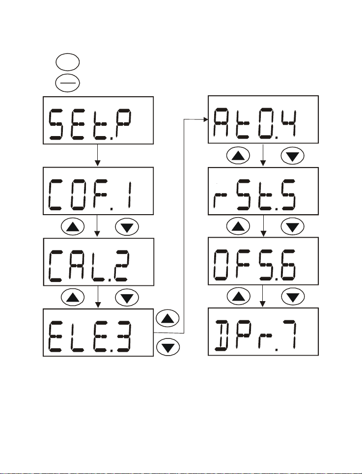
The following table combines the explanation for the features available in both
Set Up menus. Figures 19 and 20 give an overall view of the Set Up sequence
for the % Saturation or Temperature Set Up menu and the mg/L (ppm)
Concentration Set Up menu.
31
Page 37

Instruction Manual DO 6
SEt.P – Enter Set Up Menu
COF.1 – Enter Configuration Menu
A.ATC – Selection for automatic temperature compensation.
b.DO – Selection of mg/L or ppm of the concentration mode
measurement. (Only available in Concentration Set
Up menu)
CAL.2 – Viewing the latest Calibration data
‘View only’ parameter for the latest calibration data
of the DO % Saturation calibration and the DO
mg/L (ppm) Concentration calibration. Calibration
data will be viewed according to its respective Set
Up menu.
ELE.3 – Viewing the Electrode properties
FACT – Viewing the Slope Factor
OFS – Viewing the % Saturation offset adjustment. (Only
available in % Saturation Set Up menu)
HI.mV – Viewing the mV value for 100% Saturation
LO.mV – Viewing the mV value for 0% Saturation
AtO.4 – Selection of automatic power off (20 minutes from
the last key press)
rSt.5 – Enter Reset Menu
A.CAL – Selection of Calibration Reset (Clear only
Calibration and its Data back to factory default
condition)
b.USR – Selection of User Reset (Clear all user setting back
to factory default condition)
32
Page 38

Instruction Manual DO 6
OFS.6 - % Saturation Offset Adjustment (Only available in %
Saturation Set Up menu)
DPr.7 – Enter Barometric Pressure Selection Menu
A.HG – Selection of Barometric Pressure Setting Adjustment
in mmHg
A.PA - Selection of Barometric Pressure Setting Adjustment
in Kilo Pascal
b.SAL – Enter the Salinity Setting Adjustment Menu (Only
available in mg/L (ppm) Concentration Set Up
menu)
33
Page 39
Instruction Manual DO 6
MODE
Switch off from % Saturation
or Temperature measurement
mode. Press and hold MODE
ON
key and then switch on.
OFF
SEt.P will display for
1 second
Figure 19: Overview of DO 6 % Saturation or Temperature Setup Menu
34
Page 40

Instruction Manual DO 6
MODE
Switch off from Concentration
measurement mode. Press
and hold MODE key and then
ON
switch on.
OFF
SEt.P will display for
1 second
Figure 20: Overview of DO6 Concentration Set up Menu
35
Page 41
Instruction Manual DO 6
p
7.2 (COF.1) Configuration
Menu
In this menu, the meter lets you configure the
selection of automatic temperature
compensation (A) and the selection of mg/L
or ppm mode for the mg/L (ppm)
Concentration measurement mode. (Second
feature is only available in mg/L (ppm)
Concentration Set Up menu)
HOLD
ENTER
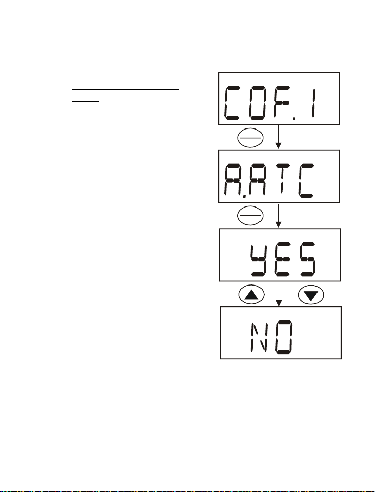
7.2.1 Selection of Automatic
Temperature Compensation
From “COF.1” of any Set Up menu,
1) Press the HOLD/ENTER key for the
display to show the Automatic
Temperature Compensation selection
menu “A.ATC”.
2) Press the HOLD/ENTER key to enter
the ATC selection menu.
3) Use the ▲ and ▼ keys to either activate
or deactivate the ATC feature.
a. YES – activates the ATC
b. NO – deactivates the ATC and
activates the Manual temperature
compensation
4) Press the HOLD/ENTER key to confirm
your selection.
36
HOLD
ENTER
Figure 21: Selection of Automatic or
Manual Temperature
ensation
Com
Page 42

Instruction Manual DO 6
Note: The meter will either return to the main group menu “COF.1” if %
Saturation or Temperature Set Up menu is used or will continue to the mg/L or
ppm mode configuration if mg/L (ppm) Concentration Set Up menu is used.
37
Page 43
Instruction Manual DO 6
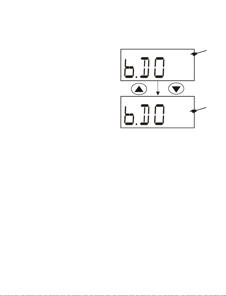
7.2.2 Selection of mg/L or ppm mode
From the “COF.1” of the mg/L (ppm)
Concentration Set Up menu,
mg/l
1) Press the HOLD/ENTER key thrice
to enter the mg/L or (ppm) mode
selection menu “b.DO”.
2) Use the ▲ and ▼ keys to select
the desired mode of measurement.
3) Press the HOLD/ENTER key to
confirm the selection made and to
return to the subgroup menu.
ppm
4) Press the CAL key to return to the
measurement mode.
Figure 22: Selection of mg/L or ppm
mode
38
Page 44

Instruction Manual DO 6
7.3 (CAL.2) Calibration Data
You can view the latest calibration data
for the % Saturation and the mg/L (ppm)
Concentration calibrations. The calibration
data from each mode can be viewed in the
Set Up menu respectively.
HOLD
7.3.1 Viewing the % Saturation
calibration data
ENTER
CAL
From the % Saturation or Temperature Set
Up menu,
1) Press the ▲ and ▼ keys to scroll
through the main group to enter the
viewing menu “CAL.2” for the latest
calibration data.
2) Press HOLD/ENTER key to view the
latest % Saturation calibration data.
Display will show the latest % saturation
calibration if set up menu is selected from the
DO % Saturation Mode
CAL
%
mg/l
3) To exit to the main group menu, press
the HOLD/ENTER key or the CAL
key.
4) Press the CAL key to return to the
measurement mode.
7.3.2 Viewing the mg/L (ppm)
Display will show the latest mg/l or ppm
calibration if set up menu is selected from the
DO mg/l (ppm) Concentration Mode
Figure 23: Viewing the last calibration
data for each measurement range
Concentration calibration data
From the mg/L (ppm) Concentration Set Up mode,
1) Repeat process 1 to 4 above to view the latest mg/L (ppm) Concentration
calibration data.
39
Page 45

Instruction Manual DO 6
7.4 (ELE.3) Electrode Properties
This menu features data of the electrode properties for diagnostic purposes.
The “view only” parameters such as the electrode Slope Factor, % Saturation
Offset setting, 100% Saturation mV value and 0% Saturation mV value are very
useful in determining the life efficiency of the electrode. These electrode
properties can be examined through its data in % Saturation and mg/L (ppm)
Concentration which is available in their Set Up menu respectively.
7.4.1 Viewing the electrode Slope Factor
This parameter lets you view and gives an indication of the probe’s efficiency.
The value displayed is the ratio of the actual value produced by the probe to the
theoretical value. The higher the number, the lower the mV output from the
probe. The ratio displays from 0.5 to 1.999.
From the % Saturation or Temperature Set Up menu,
1) Enter the Set Up menu & scroll by using the ▲ and ▼ keys until the meter
displays the Electrode Properties menu “ ELE.3”
2) Press the HOLD/ENTER key to enter the menu and view the Slope Factor
of the electrode.
3) The display will momentarily shows “FACT” before displaying the slope
factor value.
7.4.2 Viewing the % Saturation Offset (Only available in % Saturation
or Temperature Set Up menu):
This parameter shows you the amount of the % Saturation Offset entered in the
other parameter “OFS” (refer to Section 7.7 for instructions).
From Step 3 above,
4) Press the HOLD/ENTER key to enter the % Saturation Offset viewing
menu.
5) The meter will display “OFS” momentarily before displaying the last offset
adjustment made.
40
Page 46

Instruction Manual DO 6
7.4.3 Viewing the 100% Saturation mV value
This parameter shows the sensor’s mV output corresponding to 100%
Saturation.
From Step 5 above,
6) Press the HOLD/ENTER key. The display will show “HI.mV” momentarily
before displaying the sensor’s mV output value with respect to 100%
Saturation.
7.4.4 Viewing the 0% Saturation mV value
This parameter lets you view the sensor’s mV output corresponding to 0%
Saturation.
From Step 6 above,
7) Press the HOLD/ENTER key. The display will show “LO.mV” momentarily
before displaying the sensor’s mV output value with respect to 0%
Saturation.
8) Press the HOLD/ENTER key again to exit to the main group menu. Press
CAL to return to the measurement mode.
Note: To view the electrode properties in the mg/L (ppm) Concentration mode,
repeat the whole steps above using the mg/L (ppm) Concentration Set Up
menu. Viewing of the % Saturation Offset will be skipped in this menu.
41
Page 47

Instruction Manual DO 6
HOLD
ENTER
“FACT” displays for
1.5 seconds
Viewing of the offset
percentage adjustment will be
available only if set up menu is
selected from the DO %
Saturation or the Temperature
Mode. Otherwise, this menu
will be skipped.
HOLD
ENTER
“HI.mV” displays
for 1.5 seconds
HOLD
ENTER
“LO.mV ” displays
for 1.5 seconds
Figure 24: Viewing electrode data sequence
42
HOLD
ENTER
“OFS” disp lays for
1.5 seconds
%
Page 48
Instruction Manual DO 6
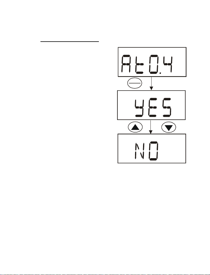
7.5 (AtO.4) Automatic Off
This feature is useful for batteries energy
conservation. The meter automatically
shuts off 20 minutes from the last key
press.
From any Set Up Menu,
1) Scroll the Set Up main group menu
by using the ▲ and ▼ keys until the
meter displays the Automatic Off
menu “AtO.4”.
2) Press the HOLD/ENTER key to enter
the menu.
3) Use the ▲ and ▼ keys to activate or
deactivate the automatic off selection.
a. YES – activates Automatic Off
b. NO – deactivates Automatic
Off
4) Press the HOLD/ENTER key to
confirm the selection.
5) Press the CAL key to exit the Set Up
menu to return to the measurement
mode.
HOLD
ENTER
Figure 25: Selection of Automatic
Off function
43
Page 49

Instruction Manual DO 6
7.6 (rSt.5) Reset to Factory Default
This mode lets you reset all parameters to
factory default settings. There are two
levels of reset:
1) Calibration Reset: - Reset only the
calibration values. This clears all
previous calibrated values and reset
to factory default. See Section 11 for
factory default settings.
2) User Reset: - Clears all data including
calibration and other customized
setup functions and reset it to factory
default. See Section 11 for factory
default settings.
7.6.1 Calibration Reset
From any Set Up menu:
1) Scroll the Set Up main group menu
by using the ▲ and ▼ keys until the
meter displays the Reset to Factory
Default menu “rSt.5”.
2) Press the HOLD/ENTER key to enter
the menu.
3) Press the HOLD/ENTER key to enter
the Calibration Reset menu “A.CAL”.
4) Use the ▲ and ▼ keys to activate or
deactivate the Calibration Reset
selection.
a. YES – activates Calibration
Reset
HOLD
ENTER
selection
Calibration
Reset
HOLD
ENTER
Figure 26: Calibration reset
44
Page 50

Instruction Manual DO 6
b. NO – deactivates Calibration Reset
5) Press HOLD/ENTER key to confirm the selection made.
6) If selection is ‘YES’, meter would immediately return to measurement
mode. Otherwise it will return to the main group menu. Press CAL to return
to the measurement mode.
Note: When you reset your meter from % Saturation Set Up menu, both %
Saturation and mg/L (ppm) Concentration calibrations are reset to factory
default. However, calibration reset in the mg/L (ppm) Concentration Set Up
menu will only reset the calibration in the concentration mode and do not affect
the calibration in the percentage saturation mode.
45
Page 51

Instruction Manual DO 6
7.6.2 User Reset
This program clears all data including
calibration and other customized setup
functions and reset it to factory default.
You can skip Calibration Reset and
proceed straight to User Reset
From “rSt.5” menu,
HOLD
ENTER
User Reset
1) Press HOLD/ENTER key three times
until meter displays the User Reset
menu “b.USR”
2) Press HOLD/ENTER key to enter the
menu.
3) Use the ▲ and ▼ keys to activate or
deactivate the User Reset selection.
a. YES – activates User Reset
b. NO – deactivates User Reset
4) Press HOLD/ENTER key to confirm
the selection made.
5) If selection is ‘YES’, meter would
Figure 27: User Reset Selection
immediately return to measurement
mode. Otherwise it will return to the
main group menu. Press CAL to return to the measurement mode.
46
Page 52

Instruction Manual DO 6
7.7 (OFS.6) % Saturation
Offset Adjustment
This is a useful feature that allows
you to offset meter’s value when
cross referenced with another DO
meter. That way, it can be
standardized without you having to
perform manual calculation. Your DO
6 meter allows % Saturation Offset
adjustment within +/- 10.0% offset
and its adjusted offset value can be
viewed in the Electrode Properties
menu “ELE.3”.
From the % Saturation measurement
mode,
1) Dip the DO electrode in the
sample solution and allow the
reading to stabilize.
2) Check the reading of another
DO meter being used as a
reference. This reference meter
should have its probe immersed
in the same sample solution and
at the same depth.
3) Switch off your meter and enter
the % Saturation Set Up menu.
4) Scroll the Set Up main group
menu by using the ▲ and ▼
keys until the meter displays the
% Saturation Offset Adjustment
menu “OFS.6”.
5) Press the HOLD/ENTER key to
enter the menu. The display will
Display will return to “OFS.6” subgroup menu
47
HOLD
ENTER
%
Measured reading based on last
percentage saturation calibration
is displayed momentarily
%
Last offset adjusted
value will be displayed
%
HOLD
ENTER
“CO” will dis play for
1.5 seconds
Figure 28: % Saturation Offset
Adjustment
Page 53

Instruction Manual DO 6
momentarily show the measured reading based on the last calibration
before displaying the last offset adjusted value.
6) Use the ▲ and ▼ keys to enter the new value.
7) Press the HOLD/ENTER key to confirm the offset adjustment. “CO” will be
displayed for 1.5 seconds before the display returns to the subgroup
menu.
8) Press CAL key to exit the Set UP menu to return to the measurement
mode.
Note: When a user calibration is done, the offset gets reset to zero.
48
Page 54

Instruction Manual DO 6
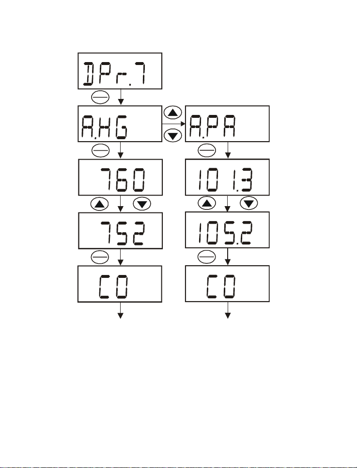
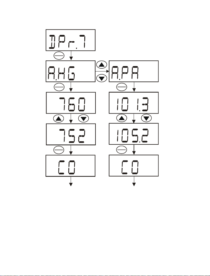
7.8 (DPr.7) Dissolved Oxygen Parameters
This Set Up menu allows you to set the barometric pressure and the salinity
value of the sample to be measured. You are given the option to use mmHg or
kilo Pascal barometric pressure units. The Salinity value to be entered will be
based on ppt and is available in mg/L (ppm) Concentration Set Up menu.
The Set Up menu for barometric pressure correction is “A.Hg” (for mmHg) and
“A.PA” (for kilo Pascal) whereas the Salinity menu is indicated as “b.SAL”.
7.8.1 Pressure Setting Adjustment
1) Switch off your meter in mg/L (ppm) Concentration mode.
2) While pressing and hold the MODE key, switch on the meter by pressing
the ON/OFF key.
3) Once the ON/OFF key is released, the meter will enter the Set Up menu by
displaying “SEt.P”. By releasing the MODE key, the display will show the
configuration menu “COF.1”.
4) Press the ▲ and ▼ keys to scroll through the Set Up main group menu till
the display shows “DPr.7”.
5) Press the HOLD/ENTER key and the meter will enter the barometric
pressure unit selection menu with the display showing either the “A.HG”
mode or “A.PA” mode.
6) Use the ▲ and ▼ keys to toggle between the barometric pressure units
and press the HOLD/ENTER key to confirm selection.
7) Use the ▲ and ▼ keys to set the pressure value and press the
HOLD/ENTER to confirm the setting. A confirmation indicator “CO” will be
displayed for 1.5 seconds before the meter shows the next display of
Salinity setting “b.SAL”. If the Set Up menu is derived from other than the
mg/L (ppm) Concentration mode, the meter will return to the Set Up
subgroup menu “DPr.7”.
8) Press CAL key to return to measurement mode, or continue to make a
salinity setting adjustment.
49
Page 55
Instruction Manual DO 6
HOLD
ENTER
HOLD
ENTER
HOLD
ENTER
“CO” will display
Display will cont inue to
Salinity setting menu
“b.SAL” if Set Up menu is
entered from m g/l (ppm)
mode. Otherwise display will
return back to “DPr.7”
for 1.5 seconds
Figure 29: Pressure Setting Adjustment Sequence
HOLD
ENTER
HOLD
ENTER
“CO” will display
for 1.5 seconds
Display will cont inue to
Salinity setting menu
“b.SAL” if Set Up menu is
entered from mg/l (ppm)
mode. Otherwise display will
return back to “DPr.7”
50
Page 56

Instruction Manual DO 6
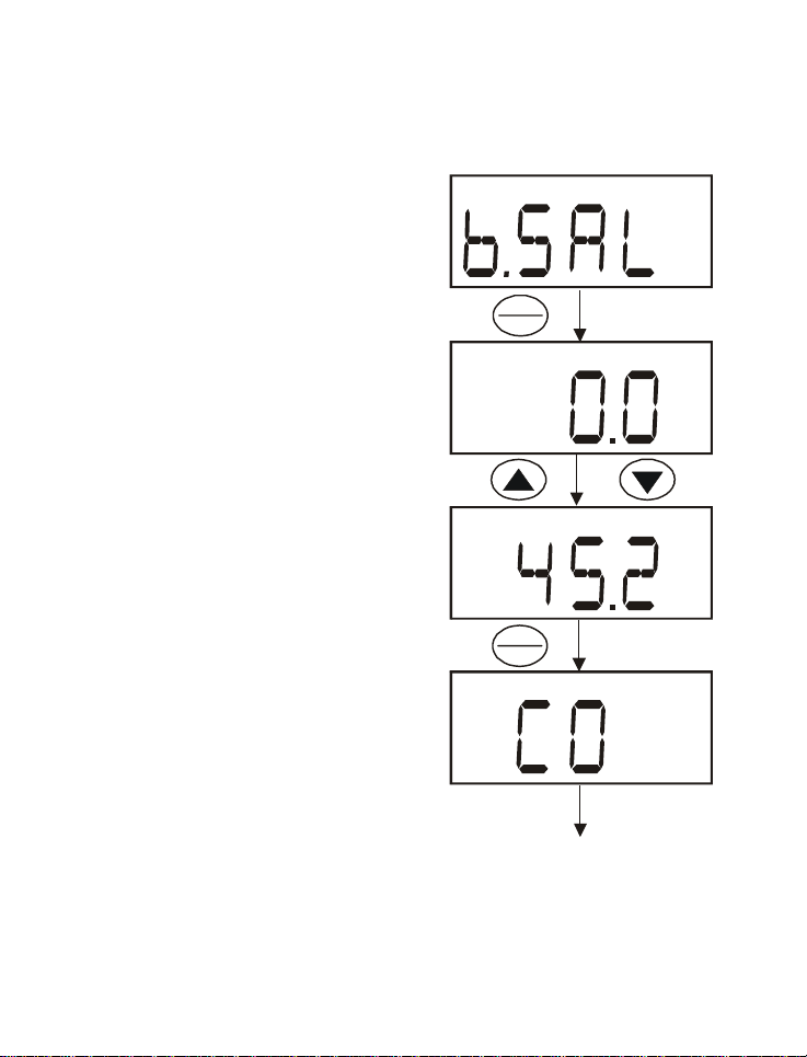
7.8.2 Salinity Setting Adjustment
Note: This mode is available only from the
mg/L (ppm) Concentration Set Up menu.
1) Repeat steps 1 to 5 as in the steps of
Pressure Setting Adjustment.
2) Press the HOLD/ENTER key twice till
the meter displays the Salinity setting
HOLD
ENTER
mode “b.SAL”.
3) Press the HOLD/ENTER key to enter
the Salinity setting mode.
4) Use the ▲ and ▼ keys to enter the
salinity of your solution in ppt.
Note: The salinity value is in ppt (parts per
thousand)
5) Press HOLD/ENTER key to confirm
the value. A confirmation indicator
“CO” will be displayed for 1.5 seconds
before returning to the subgroup
menu “DPr.7”.
6) Press CAL key to return to the
HOLD
ENTER
measurement mode.
Display will return back to “DPr.7”
subgroup menu
Figure 30: Salinity Setting
Adjustment Sequence
51
“CO” will display for
1.5 seconds
Page 57

Instruction Manual DO 6
8 PROBE CARE AND MAINTENANCE
The DO6 probe is a galvanic measuring element which produces an output
proportional to the oxygen present in the medium in which it is placed. The
galvanic probe design lets you take measurements immediately – without the
typical 15 minute wait of other dissolved oxygen probes.
The probe consists of two parts:
• An upper part consisting of the anode, a cathode, and the dual cable.
• A lower part consisting of a pre-membraned cap, and electrolyte
solution.
Oxygen diffuses through the membrane onto the cathode, where it is
consumed. This process produces an electrical current which flows through the
cable to the meter. The electric current produced is proportional to the oxygen
that passes through the membrane and the layer of electrolyte. This makes it
possible to measure the partial pressure of oxygen in the sample at a given
temperature.
Since the DO in the sample is consumed by the cathode it is essential that a
new sample must flow past the membrane of the probe to prevent the
occurrence of false readings. The probe uses very little oxygen for its
measurement. This enables it to function correctly with liquid movement as low
as 2 inch /sec across membrane.
The permeability of the membrane to oxygen varies greatly with temperature.
Therefore compensation is needed for this variation. The DO6 probe comes
with an in-built Temperature Compensation for the membrane variation.
52
Page 58

Instruction Manual DO 6
8.1 Probe Care
Proper care and maintenance will help you receive the maximum probe life and
ensure more accurate readings.
Since any deposits on the membrane surface act as a barrier to oxygen
diffusing through the membrane, the membrane must be cleaned at regular
intervals to assure maximum reliability.
After using the probe, rinse the probe with clean water and wipe it with a soft
cloth or paper to avoid any hardening of deposits if necessary. If growth
develops on the probe, use a disinfecting chemical to clean.
NOTE: Although the membrane is strong and not easily damaged, wipe it gently
while cleaning it. If the membrane is damaged or torn, the probe will no longer
function.
There are no special probe storage requirements.
8.2 Pre-Membraned Caps Replacement
Replacement of the pre-membraned cap is required only when you cannot
calibrate the probe, or if the membrane is damaged.
Typical membrane damages are punctures or wrinkles caused during
measurements or cleaning.
To order replacement probe components or a replacement probe, see Section
13 “Accessories” on page 62.
53
Page 59
Instruction Manual DO 6
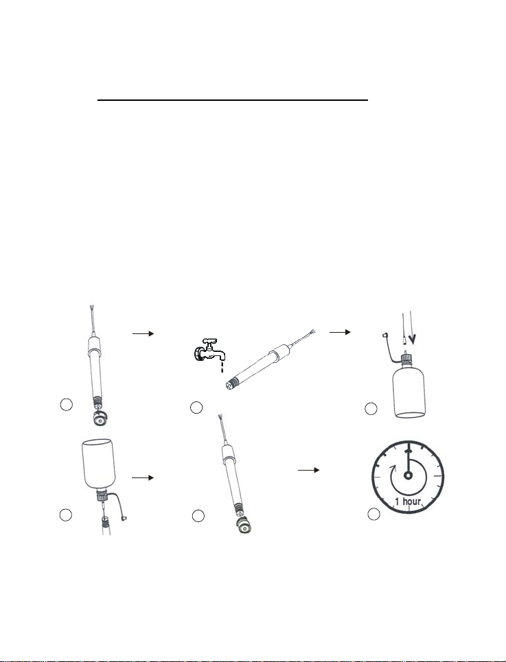
8.3 To replace the probe pre-membraned cap
1) Unscrew counter clockwise the pre-membraned cap from the probe
sensing tip and discard.
2) Wash the probe under running water.
3) Take out the bottle of refill solution provided and assemble the needle tip
on the tip of the plastic bottle.
4) Hold the probe upside down. Insert the needle into one of the 4 holes
surrounding the silver cathode. Squeeze the bottle to inject fill solution into
the probe body. Inject until solution leaks out of the fill hole (approximately
5 mL).
5) Replace pre-membraned cap by tightening clockwise until hand tightened.
6) Allow at least 1 hour for the electrode to equilibrate before usage.
1
2
3
4
5
6
Figure 31: probe pre mebraned cap replacement process
54
Page 60

Instruction Manual DO 6
8.4 Electrolyte Solution
The electrolyte solution in your probe’s cap will deplete on usage and will need
to be replaced periodically.
Your DO probe comes with replacement electrolyte solution. The replacement
electrolyte comes premixed and ready to use. To order more electrolyte
solution, see “Accessories” section.
55
Page 61

Instruction Manual DO 6
9 TROUBLE-SHOOTING GUIDE
Problem Cause Solution
No display
when turned
on
Unstable
readings
Slow
response
Not
responding
to key press
a) Batteries not in place
b) Batteries not in correct
polarity (+ and –
position).
c) Weak batteries
a) Insufficient electrolyte in
probe.
b) Air bubbles trapped
around the probe.
c) Dirty or damaged probe
d) Probe not deep enough
in sample.
e) External noise pickup or
induction caused by
nearby electric motor.
f) Broken probe.
a) Dirty / Oily probe.
b) Temperature is
changing.
a) HOLD mode in
operation indicated by
flashing display.
b) Damaged key pad.
c) Internal program error.
a) Remove rubber boot/stand. Check
that batteries are in place and
making good contact.
b) Re-insert batteries with correct
polarity.
c) Replace batteries.
a) Fill probe with electrolyte &
replace pre-membraned cap.
b) Stir or tap probe to remove
bubbles.
c) Clean the probe and re-calibrate.
d) Make sure sample entirely covers
the probe sensors.
e) Move or switch off interfering
motor.
f) Replace probe.
a) Clean probe. See “Probe Care &
Maintenance.
b) Allow time for temperature to
stabilize
a) Cancel HOLD mode.
b) Return to dealer.
c) Reset all internal programs by
reinserting batteries.
56
Page 62
Instruction Manual DO 6
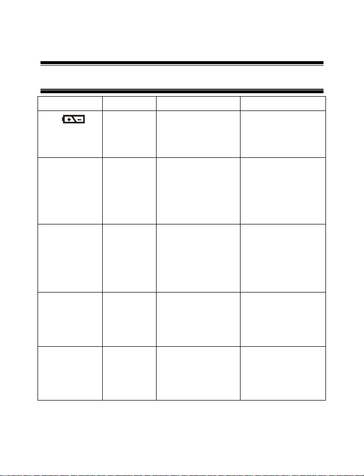
10 ERROR MESSAGES
LCD Display Indicates Cause Solution
Low
Battery
indicator
“Err 1” in %
Saturation Mode
Low battery
level.
% Saturation
Calibration
error
Need new batteries or
battery connection is
bad.
Calibration is
performed when factory
calibrated absolute
value is out of
calibration range –
10.1% to 49.9%
Clean battery contacts.
Replace batteries with
fresh ones, noting
polarity.
Check the value of the
calibration solution. If
zero calibration is done,
make sure the limit of
10% is not exceeded.
If message persist,
recondition your probe.
“Err. 1” in mg/L
(ppm)
Concentration
Mode
“UR”/”OR” with
blinking “A”
annunciator in
Temperature
Mode
“----“with blinking
“A” annunciator
in % Saturation
and
Concentration
Mode
Concentration
Calibration
error
ATC probe
error, Under
Range, Over
Range
ATC probe
error
Calibration is
performed when the
calibration solution
factory absolute
measurement is below
2.00 mg/L or ppm
ATC probe is removed
or broken while the
meter has the ATC
feature activated.
ATC probe is removed
or broken while the
meter has the ATC
feature activated.
57
Check the calibrating
solution to be above 2
mg/L or ppm.
Check that the correct
temperature and salinity
setting has been set
prior calibration.
Check the probe’s
temperature input
phono jack connection
to the meter. Ensure
probe is not broken or
punctured.
Check the probe’s
temperature input
phono jack connection
to the meter. Ensure
probe is not broken or
punctured.
Page 63
Instruction Manual DO 6
11 FACTORY DEFAULT SETTINGS
Setting
Menu
COF.1 Unit Configuration Parameter Title
A.ATC Selection of Automatic or
b.DO Selection of mg/L or ppm of
CAL.2 Viewing the latest
ELE.3
FACT Viewing the Slope Factor Viewing Only Viewing Only 1.000
OFS Viewing the % Saturation
HI.mV Viewing the mV value for
LO.mV Viewing the mV value for
AtO.4 Selection of automatic
rSt.5
A.CAL Selection of Calibration
b.USR Selection of User Reset
OFS.6 Offset Adjustment
FUNCTION PARAMETER
Manual Temperature
Compensation
the concentration mode
calibration data
Viewing the Electrode
properties
offset adjustment.
100% Saturation
0% Saturation
power off
Reset to factory defaults
Reset
(% Saturation)
OPTING KEYS
Only
▲ and ▼ YES; NO YES
▲ and ▼ mg/L or ppm mg/L
Viewing Only Viewing Only _ _ _ _
Parameter Title
Only
Viewing Only Viewing Only 0.0%
Viewing Only Viewing Only
Viewing Only Viewing Only
▲ and ▼ YES; NO YES
Parameter Title
Only
▲ and ▼
▲ and ▼
▲ and ▼ +/- 10.0 of
PARAMETER
OPTIONS
Parameter
Title Only
Parameter
Title Only
Parameter
Title Only
NO, YES
NO, YES
measured
reading
DEFAULT
SETTING
50 mV
0 mV
NO
NO
0.0%
58
Page 64

Instruction Manual DO 6
Setting
Menu
DPr.7
A.HG Selection of Barometric
A.PA Selection of Barometric
b.SAL Salinity Setting Adjustment
Setting the Manual
FUNCTION PARAMETER
Barometric Pressure
Selection Menu
Pressure Setting
Adjustment in mmHg
Pressure Setting
Adjustment in Kilo Pascal
Temperature Compensation
OPTING KEYS
Parameter Title
Only
▲ and ▼
▲ and ▼
▲ and ▼
CAL, ▲ and ▼
PARAMETER
OPTIONS
Parameter
Title Only
500 to 1499
mmHg
66.6 to 199.9
kPA
0.0 to 50.0 ppt 0.0 ppt
0.0 to 50.0 °C 25.0°C
DEFAULT
SETTING
760 mm
101.3 kPA
Note: The HOLD/ENTER key is used to confirm every parameter opted.
Hg
59
Page 65

Instruction Manual DO 6
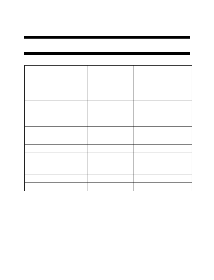
12 SPECIFICATIONS
% Saturation Mode
Range
Resolution
Relative accuracy
mg/L (ppm) Concentration Mode
Range
Resolution
Relative accuracy
Temperature
Range
Resolution
Relative accuracy
Salinity Correction
Range
Resolution
Method
Barometric Pressure Correction (mm Hg)
Range
Resolution
Method
Automatic Temperature Compensation 0.0 to 50.0°C
Manual Temperature Compensation 0.0 to 50.0°C
Probe (DO / Temp) Galvanic / Thermistor
Probe Diameter Body 12 mm, Cap 16 mm
Response Time 60 seconds to achieve 95% of the reading
% Saturation Calibration Points 100% in saturated air or air-saturated
0.00 – 200.0 %
0.1 %
± 1.5% of Full Scale
0.00 – 20.00 mg/L or ppm
0.01 mg/L; 0.01 ppm
± 1.5% of Full Scale
-5.0 – 105.0 °C
0.1 °C
± 0.5 °C
0.0 – 50.0 ppt
0.1 ppt
Automatic correction after manual input
500 to 1499 mm Hg or 66.6 to 199.9 kPA
1 mm Hg or 0.1 kPA
Automatic correction after manual input
water.
0% in zero oxygen solution
60
Page 66
Instruction Manual DO 6
% Saturation Calibration Limits Factory calibrated absolute value of 10.0%
Concentration Calibration Window +/- 40% from the factory default
Temperature Calibration Window +/- 5°C from factory default measurement
Offset Adjustments (% Saturation) +/- 10.0 of reading in Saturation mode
HOLD function Yes
Auto-Off function Selectable Auto Off function. (20 minutes
Display Customs Single 4 Digit LCD
Inputs BNC for DO & 2.5 mm Phono for
Operating Range 0 to 50 °C
Power Requirements 4 AAA-sized batteries (included)
Battery Life > 700 hours (Alkaline Batteries)
Dimensions Meter: 14 cm (L) x 7 cm (W) x 3.5 cm (H)
and below for 0% point & 50% to 200% for
100% point.
measurement value. Minimum reading
allowed is 2.00 mg/L (ppm).
after last key press)
temperature
Probe: 115 mm (L) x 12 mm (Dia) with 3-ft
cable.
Probe’s membrane housing: 16 mm (Dia)
61
Page 67
Instruction Manual DO 6
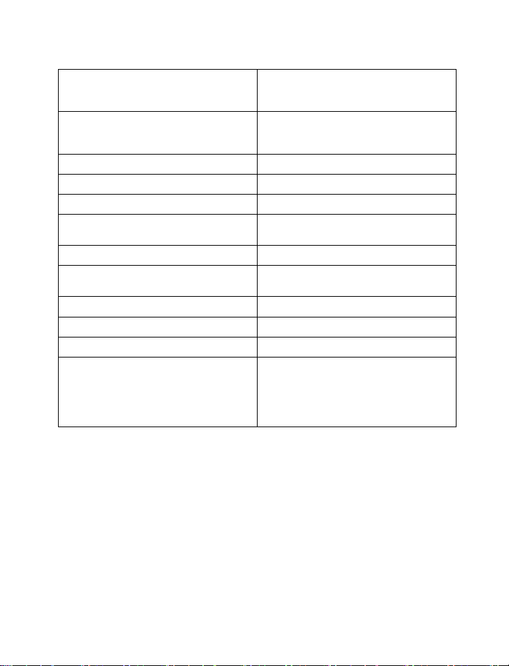
13 ACCESSORIES
Eutech Instruments Oakton Instruments
DO 6 meter and probe kit in
hard carrying case
DO 6 meter and probe ECDO601
Replacement galvanic DO
probe with 10-mL electrolyte.
12-mm dia, 1 meter cable.
DO probe refilling electrolyte 01X211226 (50 mL) 35640-71 (500-mL)
Replacement cap with preinstalled membrane and 10-mL
electrolyte
Hard carrying case ECECODRYKIT 35632-97
Zero oxygen solution, 500-mL - 00653-00
Replacement Rubber
Boot/Stand
Replacement AAA batteries 60X023200 09376-00 (pack of 12)
Pre-membraned Housing 01X241608 -
ECDO601K
“Ecoscan DO6”
“Ecoscan DO6”
ECDO6HANDY 35642-50
01X241609 35642-55
ECRUBBERBOOT 35606-80
35642-60
“Acorn DO6”
35642-10
“Acorn DO6”
62
Page 68

Instruction Manual DO 6
14 ADDITIONAL INFORMATION
14.1 Dissolved Oxygen
14.1.1 General Information
Dissolved Oxygen (DO) refers to the volume of oxygen that is contained in
water. There are two main sources of DO in water: from atmosphere and
photosynthesis. Waves and tumbling water mix air into the water where oxygen
readily dissolves until saturation occurs. Oxygen is also produced by aquatic
plants and algae as a by-product of photosynthesis.
The amount of DO that can be held by water depends on 3 factors: water
temperature, salinity, and atmospheric pressure.
1) Amount of DO increases with decreasing temperature (colder water holds
more oxygen);
2) Amount of DO increases with decreasing salinity (freshwater holds more
oxygen than saltwater does);
3) Amount of DO decreases with decreasing atmospheric pressure (amount
of DO absorbed in water decreases as altitude increases).
63
Page 69
Instruction Manual DO 6
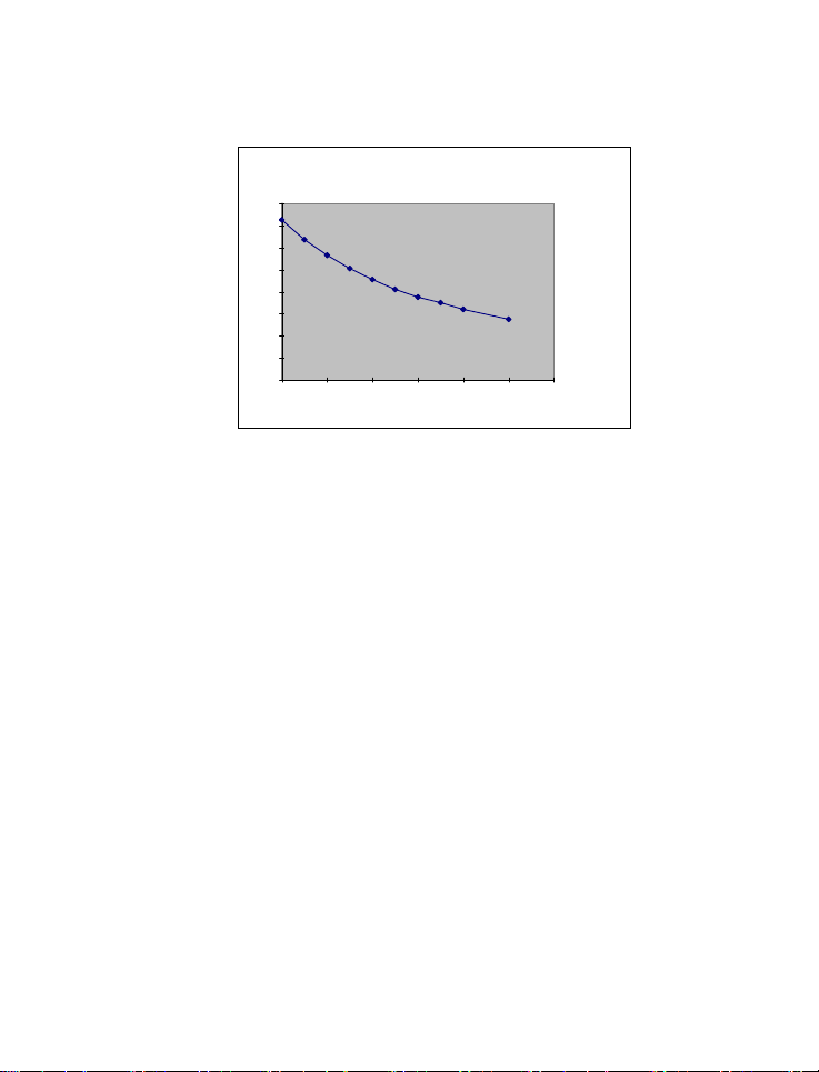
The chart in Figure 32 shows the solubility of DO in mg/L in water at various
temperatures.
Solubility of oxygen in water contact with water saturated air at
16
14
12
10
8
6
Solubility mg/L
4
2
0
0 102030405060
standard atmospheric pressure
Temperature °C
Figure 32: DO Solubility in Water vs Temperature °C
64
Page 70

Instruction Manual DO 6
14.1.2 Measurement Units
One measure of DO in water is parts per million (ppm) which is the number of
oxygen molecules (O
) per million total molecules in a sample. Calculating the
2
% Saturation is another way to analyze DO levels. % Saturation is the
measured DO level divided by the greatest amount of oxygen that the water
could hold under various temperature and atmospheric pressure conditions
multiplied by 100.
14.1.3 What Is Being Measured?
DO probes respond to the partial pressure of oxygen in liquid or gas being
measured – they measure the “pressure” of oxygen rather than concentration.
All of the oxygen entering the probe is consumed at the cathode where it is
electrochemically reduced to hydroxyl ions producing an electrical current within
the probe:
+ 2 H2O + 4 e- Æ 4 OH –
O
2
Since all oxygen entering the probe is chemically consumed, the partial
pressure of oxygen in the electrolyte is zero. Therefore, a partial pressure
gradient exists across the membrane and the rate at which oxygen enters the
probe is a function of the partial pressure of oxygen in the gas or in liquid being
measured.
When a probe is placed in air saturated water, the current it produces will not be
affected by the temperature or salinity of the water. The DO concentration in
the water, however, will vary with temperature and salinity. Because it is
convenient to report DO concentration in mg/L or ppm, it is necessary to adjust
for temperature and salinity of the water to get correct readings in these units.
If DO were to be reported in terms of partial pressure or % Saturation, then
temperature and/or salinity compensation for oxygen solubility would not be
necessary. Most probes are temperature compensated – i.e. they convert the
“partial pressure measurement” to mg/L of DO at whatever temperature the
water happens to be at for a given salinity and barometric pressure.
65
Page 71

Instruction Manual DO 6
14.1.4 Air Calibration
Understanding the principle of air calibration is easy, once you know that it is
partial pressure that the probe is responding to. When the probe is in air, it is
measuring the partial pressure of oxygen in air. If water is air saturated, then
the partial pressure of oxygen in the water will be the same as it is in air.
Therefore, all you need to know is the temperature of the air in which the probe
is placed. By consulting solubility tables for oxygen at the particular barometric
pressure and salinity of the water being measured, the corresponding
concentration (mg/L or ppm) can be found for air saturated water at the air
calibration temperature, and the meter can be set accordingly. Because most
meters are temperature compensated, they will still give correct readings in
mg/L even though the actual water temperature may be different to the air
calibration temperature.
Note: The closer the air calibration temperature to the water temperature, the
more accurate is the calibration.
14.1.5 Applications
Oxygen is essential for fish, invertebrate, plant, and aerobic bacteria respiration.
DO levels below 3 ppm are stressful to most aquatic organisms. Levels below 2
or 1 ppm will not support fish. Fish growth and activity usually require 5 to 6
ppm of DO, an important consideration for Aqua-culture industry.
Low DO indicates a demand on the oxygen of the system. Natural organic
material such as leaves accumulate in the stream and create an oxygen
demand as it is decomposed. Organic materials from human activities also
create an oxygen demand in the system. Micro-organisms consume oxygen as
they decompose sewage, urban and agricultural run-off, and discharge from
food-processing plants, meat-packing plants and diaries. There is an optimum
DO level for this process and if DO level falls too low, the micro-organisms die
and the decomposition ceases. If DO level is too high, more power is used than
necessary for aeration and the process becomes costly.
66
Page 72

Instruction Manual DO 6
In boiler water application, presence of oxygen in the water will increase
corrosion and helps build up boiler scale that inhibits heat transfer. In such
instance it is critical to keep DO concentration to a minimum.
Some pollutants such as acid mine drainage produce direct chemical demands
on oxygen in the water. DO is consumed in the oxidation-reduction reactions of
introduced chemical compounds such as nitrate (NO
sulfate (SO
2-
), and sulfite (SO
4
2-
) and ferrous (Fe
3
1-
) and ammonia (NH
3
+
) and ferric (Fe
2
+
) ions.
3
1+
),
4
These are important consideration for water and wastewater treatment industry.
67
Page 73

Instruction Manual DO 6
15 WARRANTY
This meter is supplied with a three-year warranty, six-month warranty for
electrode against significant deviations in material and workmanship.
If repair or adjustment is necessary and has not been the result of abuse or
misuse within the designated period, please return – freight pre-paid – and
correction will be made without charge. Eutech Instruments/ Oakton
Instruments will determine if the product problem is due to deviations or
customer misuse.
Out of warranty products will be repaired on a charged basis.
Exclusions
The warranty on your instrument shall not apply to defects resulting from:
• Improper or inadequate maintenance by customer
• Unauthorized modification or misuse
• Operation outside of the environment specifications of the products
68
Page 74

Instruction Manual DO 6
16 RETURN OF ITEMS
Authorization must be obtained from our Customer Service Department or
authorized distributor before returning items for any reason. A “Return Goods
Authorization” (RGA) form is available through our Authorized Distributor.
Please include data regarding the reason the items are to be returned. For your
protection, items must be carefully packed to prevent damage in shipment and
insured against possible damage or loss. Eutech Instruments/ Oakton
Instruments will not be responsible for damage resulting from careless or
insufficient packing. A restocking charge will be made on all unauthorized
returns.
NOTE:
Eutech Instruments Pte Ltd/ Oakton Instruments reserve the right to make
improvements in design, construction, and appearance of products without
notice.
69
Page 75

Page 76

For more information on Eutech Instruments/ Oakton Instruments’ products,
contact your nearest distributor or visit our website listed below:
Oakton Instruments
P.O Box 5136,
Vernon Hills, IL 60061, USA
Tel: (1) 888-462-5866
Fax: (1) 847-247-2984
E-mail: info@4oakton.com
Web-sites:
www.4oakton.com
www.oaktoninstruments.com
Eutech Instruments Pte Ltd.
Blk 55, Ayer Rajah Crescent,
#04-16/24 Singapore 139949
Tel: (65) 6778 6876
Fax: (65) 6773 0836
E-mail: marketing@eutechinst.com
Web-site: www.eutechinst.com
Distributed by:
 Loading...