

Page 1
Instruction Manual
gyM
sy...
DO 700 Dissolved Oxygen/ºC/ºF
Bench Meter
Part of Thermo Fisher Scientific 68X541703 Rev. 2. Sep 2010
Tech nol o
adeEa
Page 2

Page 3

TABLE OF CONTENTS
1. INTRODUCTION.............................................................. 1
2. GETTING STARTED........................................................ 2
2.1 Keypad Functions ...................................................................2
2.2 LCD Annunciators...................................................................3
2.3 Meter Connections..................................................................3
3. DISSOLVED OXYGEN / ATC ELECTRODE................... 4
4. CALIBRATION................................................................. 5
4.1 Temperature Calibration .........................................................6
4.2 % Saturation Calibration .........................................................7
4.3 100% Calibration.....................................................................7
4.4 0% Calibration.........................................................................7
4.5 mg/L or ppm (Concentration) Calibration................................8
5. SETUP FUNCTIONS........................................................ 9
5.1 1.0 CAL (Calibration)...............................................................9
5.2 2.0 ELE (Electrode Information)..............................................10
5.3 3.0 ConF (Configuration).........................................................10
5.4 3.1 rdY (Ready Stability Indicator / Auto Hold)........................10
5.5 3.2 ºC ºF (Celsius or Fahrenheit)............................................10
5.6 3.3 dPr (Barometric Pressure Adjustment)..............................11
5.7 3.4 SALt (Salinity Adjustment) ................................................11
5.8 3.5 OFS (Offset Adjustment) from % mode.............................11
5.9 3.5 Unit (Unit Adjustment) from concentration mode...............12
5.10 4.0 rSt (Reset).........................................................................12
5.11 5.0 CLr (Clear Stored Memory)...............................................12
6. TAKING MEASUREMENTS............................................ 13
6.1 HOLD Function .......................................................................14
6.2 Storing and Recalling Data .....................................................14
7. ELECTRODE MAINTENANCE........................................ 15
8. DISSOLVED OXYGEN THEORY .................................... 18
Page 4

9.
REPLACEMENTS AND ACCESSORIES........................ 22
10. TROUBLESHOOTING GUIDE......................................... 23
11. SPECIFICATIONS............................................................ 25
12. WARRANTY..................................................................... 26
13. RETURN OF ITEMS......................................................... 27
Page 5

1. INTRODUCTION
Thank you for purchasing our DO 700 series benchtop meter.
This microprocessor-based meter is economical and simple to
use. The design incorporates a large LCD for clear viewing, yet
offers a small footprint to conserve space.
The DO 700 measures Dissolved Oxygen in % saturation or
centration (mg/L or ppm) with temperature (ºC or ºF).
con
Each meter includes a convenient slide-out card for quick
referen
ce. Also included is an electrode arm and metal bracket
which can be easily attached to the left or right side of the meter
according to your preference.
We take great pride in every instrument we manufacture
and hope
this one serves you well.
1
Page 6
2. GETTING STARTED
2.1 Keypad Functions
Powers the meter on and off. Upon power on, the meter
automatic
Calibration and memory values are retained even if meter
is unplugged.
Toggle between available measurement modes—%
saturatio
switch to Temperature calibration during DO calibration
modes.
Press and hold for 5 seconds to enter SETUP mode.
Toggles between measurement and calibration modes.
In SET
Confirms calibration values in CAL mode.
Confirms selections in SETUP mode.
View recalled values in memory mode.
S
MI (Memory Insert) stores values into memory.
ally begins in the mode that was last used.
n or concentration (mg/L or ppm). Also used to
UP mode, returns user to the measurement mode.
Increase value. Scroll up in SETUP & CAL modes.
MR (Memor
T Decrease value. Scroll down in SETUP & CAL modes.
Freezes measured reading. Press again to resume
live re
y Recall) recalls values from memory.
ading.
2
Page 7
2.2 LCD Annunciators
2.3 Meter Connections
DC
ATC
DO
Power supply
Temperature connection of Dissolved Oxygen electrode
BNC connection of Dissolved Oxygen electrode
3
Page 8

3. DISSOLVED OXYGEN / ATC ELECTRODE
The DO 700 includes a galvanic DO
electrode with built in temperature
measurement.
The electrode has a dual cable; a BNC
connector for DO measurement and a miniphono plug for temperature. The electrode is
pre-filled with electrolyte that is separated
from the sample by an oxygen permeable
membrane. The membrane is pre-assembled
for you and fixed to a detachable cap. The
pre-assembled cap design allows simple
replacement and fast conditioning.
The electrode is light-weight with a 12-mm
bod
y diameter and a 16-mm tip diameter
from at the detachable Noryl cap. The
compact sensing area reduces air
entrapment resulting in quick, accurate, and
stable readings.
Provide simple stirring for best results—
ally achieve a minimum water flow rate of
ide
2 inch/second on the membrane.
The probe is not recommended for samples
be
yond 0 to 50 °C.
The membrane is thin and can be replaced if damaged. Use care to
protect from scratches, abras
results keep membrane clean by rinsing after daily use. See Section 7
– Electrode Maintenance.
ion, or contact with solids. For best
4
Page 9
4. CALIBRATION
The DO 700 has three measurement modes; DO as % saturation, DO
as mg/L (or ppm) concentration, and temperature.
Dissolved oxygen levels vary with temperature, barometric pressure,
linity, so calibration must be performed with consideration of
and sa
these factors. It is necessary to set the proper temperature,
barometric pressure and salinity values prior to performing any
DO calibration or measurement.
See Section 4.1 — Temperature Calibration
See Section 5.6 — Barometric Pressure Adjustment.
See Section 5.7 — Salinity Adjustment.
The DO 700 will accept two % saturation calibration points; 100%
g saturated air or air-saturated water, and 0% using zero oxygen
usin
solution. When 100% or 0% calibration is performed, the concentration
value is adjusted accordingly. Therefore, it is not necessary to calibrate
the concentration mode. If calibrating for 0% oxygen, note that the
meter will take several minutes to reach 0% saturation value and
constant stirring is not required.
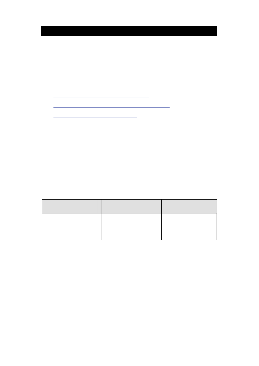
The following table lists calibration values in % saturation calibration
mode
with two different barometric pressures. Note that the saturation
value (92.1%) has decreased due to the lower barometric pressure
entered.
.
% Saturation
(of factory default value)
less than 10% 0% 0%
10.1% to 49.9% CAL ERR CAL ERR
50% to 150% 100% 92.1%
Calibration Value
(760mmHg)
Calibration Value
(700mmHg)
If calibration is attempted from 10.1% to 49.9%, CAL Err message is
shown—calibration is rejected and the display will return to calibration
mode.
5
Page 10

The DO 700 will accept one calibration point in concentration mode.
The minimum value is 2 mg/L (ppm), and the calibration window is +/40% of the factory default value.
Temperature and % saturation calibration should take place be
attempting to perform mg/L (ppm) concentration calibration.
Calibration of the concentration mode
concentration calibration and does not affect the % saturation
calibration.
To offset your % saturation reading to match
Section 5.8 – Offset Adjustment
Perform daily calibration for best results. Ne
automatically override the existing data. To completely recalibrate the
meter and when installing a replacement electrode, it is best to clear all
calibration data. See Section 5.10 – Reset
4.1 Temperature Calibration
For best DO accuracy, ensure that the temperature is accurate. The
thermistor sensor used for automatic temperature compensation and
measurement is accurate and stable, so frequent calibration isn’t
required. Temperature calibration is recommended upon probe
replacement, whenever the temperature reading is suspect, or if
matching against a certified thermometer is desired.
The DO 700 will default to 25 ºC / 77 ºF when the ATC plug is not
ected.
conn
1) Place the pr obe into a solution with a known accurate temperature
such as a co
nstant temperature bath.
will only replace the previous
another instrument, see
.
w calibration values will
.
fore
2) Press
measured temperature while the secondary displa y shows the
factory default temperature.
4) Adjust the tem
º
5
C (or ± 9ºF) from the factory default temperature.
followed by . The primary display shows the
perature using
to cancel. The meter allows an adjustable maximum value of ±
or . Press to accept or
6
Page 11

4.2 % Saturation Calibration
The DO700 can be easily calibrated in air. For best accuracy, ensure
that the barom
The barometric pressure factory default is 760 mm Hg (1.013 bar),
hich results in a theoretical calibration value of 100% saturation in air.
w
If the barometric pressure setting has been changed from 760 mm Hg,
the meter will automatically adjust to a new % saturation calibration
value instead of 100%. This new value is correct for the adjusted
barometric pressure.
4.3 100% Calibration
1) Rinse the probe well with clean water (do not dry).
etric pressure value is accurate.
2) Press
3) Hold the probe in the air with the tip facing downwards. Wait for
the read
4) Press
indicate the calibration point, 100.0.
5) Press
briefly before calibrating to 100.0%.
6) Press to return to measurement mode, or continue with 0%
calibration if desired.
4.4 0% Calibration
1) Rinse the probe well with clean water (do not dry).
2) Press
3) Submerse probe in zero oxygen calibration solution and stir
slo
more than 10 minutes!
to select % saturation.
ing to stabilize.
. The CAL indicator will blink and secondary display will
to confirm the calibration. T he primary display will blink
to select % saturation.
wly. Wait for the reading to stabilize—this can often take
7
Page 12

4) Press . The CAL indicator will blink and the secondary display
will indicate the calibration point, 0.0.
5) Press to confirm the calibration. T he primary display will blink
briefly before calibrating to 0.0%.
6) Press
calibration if desired (note 0% calibration followed by 100%
calibration is not recommended---always perform 100% calibration
first).
4.5 mg/L or ppm (Concentration) Calibration
Performing a saturation calibration at 100% or 0% will simultaneously
calibr
ate the corresponding mg/L (ppm) concentration value.
Therefore, additional mg/L (ppm) calibration isn’t required in most
circumstances.
If desired, you can perform a calibration adjustment in mg/L (ppm)
ithout affecting your % saturation calibration value.
w
1) Rinse the probe well with clean water (do not dry).
2) Press
3) Dip the probe into a sample of known oxygen concentration (i.e.
determi
to stabilize.
4) Press
briefly, before CAL flashes. The concentration value based on the
factory default calibration is shown.
5) Press
oxygen concentration value.
to return to measurement mode, or continue with 100%
to select concentration mg/L (ppm).
ned by titration or another instrument). Wait for the reading
. The CAL indicator and current concentration display
or to adjust the reading to match the known
8
Page 13

6) Press to confirm the calibration. T he primary display will blink
briefly before returning to measurement mode.
NOTE:
calibration is limited to ±40% adjustment of the factory default value to
prevent erroneous calibrations.
The minimum calibration value is 2 mg/L. In addition, the
5. SETUP FUNCTIONS
Use the setup feature to customize your instrument operation.
There are two setup menus; one menu is derived from the %
saturation mode and the other from the mg/L (or ppm) concentration
mode.
First, select the appropriate measurement mode you wish to adjust by
pressi
ng
until the desired units are displayed. During
measurement, press and hold
mode of the parameter being measured.
Press
Press to select the program or confirm selection.
Press to go back one level or return to measurement mode.
5.1 1.0 CAL (Calibration)
or to change programs or change options.
Press
Note: % saturation mode will list two points, while
concentration mode has only one point.
to view stored calibration points.
for 5 seconds to enter SETUP
9
Page 14

5.2 2.0 ELE (Electrode Information)
Press
TIP: The factor is an indication of the probe’s efficiency. It is
the ratio of the actual mV produced by the probe to the
theoretical mV value. The ratio displays from 0.5 to 1.999.
Press
Press
Press
5.3 3.0 ConF (Configuration)
Press
5.4 3.1 rdY (Ready Stability Indicator / Auto Hold)
Press
Press or to choose READY “On”, READY “OFF”, or
Auto HOLd.
Press
5.5 3.2 ºC ºF (Celsius or Fahrenheit)
Press
Press
to view calibration factor (CAL.F)
to view mV output for 100% (HI).
to view mV output for 0% (LO).
to view Offset % (OFS)—% saturation mode only.
to access set-up programs 3.1 thru 3.5.
.
to confirm.
.
or to select ºC or ºF.
Press to confirm.
10
Page 15

5.6 3.3 dPr (Barometric Pressure Adjustment)
Press
Press
Press
Press or to adjust the value, press to accept.
5.7 3.4 SALt (Salinity Adjustment)
For best accuracy, enter the actual salinity value if your samples are at
least 0.1 ppt (100 ppm). Maximum adjustment is 50 ppt (50,000 ppm or
5% salt).
Press
Press or to adjust the value (in parts per thousand).
Tip: 0.1 ppt = 100 ppm salinity
Press
5.8 3.5 OFS (Offset Adjustment) from % mode
Use this feature to offset the meter’s value to another DO meter.
Using the % saturation mode, observe the reading a sample solution
after it has stabilized. Similarly, observe the reading of the same
sample using another DO meter as a reference. The probe of the
reference meter should be immersed in the same sample at the same
depth.
The DO 700 allows +/- 10.0% offset adjustme
user calibrations will reset the offset adjustment back to the factory
default value of 0.0 %.
.
or to select units; Hg (mm Mercury) or bAr.
to confirm.
.
to confirm.
nt. Note that subsequent
Press
Press or to adjust the % offset.
.
11
Page 16

Press to confirm.
5.9 3.5 Unit (Unit Adjustment) from concentration mode
Press .
Press or to select ppm or mg/L units.
Press
5.10 4.0 rSt (Reset)
Press
Press or to select “Yes” (Reset) or “No” (Cancel).
If “Yes”, press or to select “Cal” (calibration reset
only) or “FCt” (complete reset to factory default settings).
Press
5.11 5.0 CLr (Clear Stored Memory)
Press
Press or to select “Yes” (Erase memory) or “No”.
Press
to confirm.
.
to confirm.
.
to confirm.
12
Page 17

6. TAKING MEASUREMENTS
During measurement the dissolved oxygen reading is
automatically compensated for pressure and salinity. For best
accuracy, ensure the pressure and salinity settings are adjusted
accordingly from the setup menu. The factory default value for
barometric pressure is 760 mm Hg or 101.3 bar (sea level). The
factory default value for salinity is 0.0 ppt (no salinity).
See Section 5.6 — Barometric Pressure Adjustment
See Section 5.7 — Salinity Adjustment
Press
to select the desired measurement mode:
•
Percentage Saturation (%) and Temp (
•
Concentration (mg/L or ppm) and Temp (
.
.
º
C or ºF)
º
C or ºF)
Follow these general rules when taking measurements:
•
Keep the membrane free from contact with solid
objects.
•
Provide stirring of your solution⎯this helps to overcome
oxygen consumption of the probe and prevents air
bubble entrapment.
Do not submerge the cable for extended periods.
•
•
Use with aqueous solutions only.
•
The pre-assembled cap must be completely submersed
to obtain an accurate reading in solutions.
•
Rinse the probe well with DI water or rinse solution
between measurements.
13
Page 18

6.1 HOLD Function
For prolonged observation of a reading, press
measurement mode to freeze the display. The “HOLD” indicator will
display when the reading is held. To release the held value and
resume measurement, press
memory by pressing .
6.2 Storing and Recalling Data
The DO 700 can retain up to 100 data points into memory for
later retrieval.
1) In the measur ement mode, press
into memory. The stored memory location value (StO) is briefly
displayed.
2) To recall data from memory, press . The location of the most
recent stored data is displayed first. Press
location of the desired data, then press
3) Press to return to the stored data location. Press to return
to measurement mode. To erase stored data, see Section 5.11 —
Clear Stored Memory
again or insert the held value into
to insert the measured value
.
during
or to select the
to accept.
14
Page 19

7. ELECTRODE MAINTENANCE
The DO 700 electrode produces an output proportional to the oxyge n
present in the medium in which it is placed. The galvanic probe design
allows for immediate use—unlike the typical 15 minute warm-up period
required for polargraphic electrodes.
The probe consists of two parts. The upper p
cathode, and dual cable. The lower part consists of a pre-assembled
cap, and electrolyte solution.
Oxygen diffuses through the membrane onto the cathode, where it is
consumed. This process produces an electrical current which flows
through the cable to the meter. The electric current produced is
proportional to the oxygen that passes through the membrane and the
layer of electrolyte. This makes it possible to measure the partial
pressure of oxygen in the sample at a given temperature.
Since the DO in the sample is consumed by the cathode it is essential
to have flow past the membrane of the probe to prevent the occurrence
of false readings. The probe uses very little oxygen for its
measurement. This enables it to function correctly with liquid
movement as low as 2 inch/sec across membrane.
The permeability of the membrane to oxygen varies greatly with
temperature. Therefore compensation is needed for this variation. The
DO 700 probe comes with built-in temperature compensation for the
membrane variation.
Proper maintenance will help you maximize probe life and achieve
most accurate
Deposits on the membrane surface act as a barrier to oxygen diffusing
h the membrane, so clean the membrane to assure maximum
throug
reliability. After each use, rinse the probe with clean water to avoid any
hardening of deposits or bacterial growth.
NOTE: Although the membrane is strong and not easily damaged,
wipe it gently while cleaning it. If the membrane is punctured,
damaged, or torn, the probe will not function properly.
readings.
art consists of the anode,
15
Page 20

There are no special probe storage requirements.
Cap and Electrolyte Replacement
Replacement of the pre-assembled cap is required only when you
cann
ot calibrate the probe, or if the membrane is damaged. Typical
membrane damages are punctures or wrinkles caused during
measurements or cleaning.
1) Unscrew the cap counter clockwise from the probe sensing tip.
2) Rinse the probe under running water.
3) Mount the nozzle tip onto the syringe provided. Fill the syringe
ith the refill solution through the tip of the plastic bottle.
w
4) Hold th e probe upside do wn. Insert the nozzle tip into one of the 4
hol
es surrounding the silver cathode. Inject the fill soluti on into the
probe body until solution leaks out from the fill hole (approximatel y
5 mL).
5) Replace pre-assembled cap by tightening clockwise until hand
ed.
tighten
6) Allow at least 1 hour for the electrode to equilibrate before
usage.
16
Page 21

1
2
3
4
5
6
Electrolyte Solution
The electrolyte solution in your probe’s cap will deplete on usage and
will need to be replaced periodically. The replacement electrolyte
solution included with your probe comes premixed and ready to use.
To order more electrolyte solution, see Section 9 – Replacements and
Accessories
.
17
Page 22

8. DISSOLVED OXYGEN THEORY
Dissolved Oxygen (DO) refers to the volume of oxygen that is contained in
water. There are two main sources of DO in water; atmosphere and
photosynthesis. Waves and tumbling water mix air into the water where
oxygen readily dissolves until saturation occurs. Oxygen is also produced
by aquatic plants and algae during photosynthesis.
The amount of DO that can be held b
1) TEMPER
ATURE:
y water depends on 3 factors:
DO increases with decreasing temperature
(colder water holds more oxygen)
ALINITY:
2) S
DO increases with decreasing salinity
(freshwater holds more oxygen than saltwater does)
TMOSPHERIC PRESSURE:
3) A
DO decreases with decreasing atmospheric pressure
(amount of DO absorbed in water decreases as altitude increases)
Solubility of oxygen in water contact with water saturated air at
16
14
12
10
8
6
Solubility mg/L
4
2
0
0 5 10 15 20 25 30 35 40 45 50
standard atmospheric pressure
Tem perat ure ° C
DO Solubility in Water vs. Temperature
18
Page 23

Measurement Units
One measure of DO in water is parts per million (ppm) which is the
number of oxygen molecules (O
) per million total molecules in a sample.
2
The “mg/L” unit is equivalent to ppm (a liter of water weighs 1 million
milligrams—one part in a million is similar to one milligram in a liter).
Calculating the % saturation is another way to analyze DO levels. %
saturation is the measured DO level divided by the greatest amount of
oxygen that the water could hold under various temperature and
atmospheric pressure conditions multiplied by 100.
What Is Being Measured?
DO probes respond to the partial pressure of oxygen in liquid or gas being
ed—they measure the “pressure” of oxygen rather than
measur
concentration. All of the oxygen entering the probe is consumed at the
cathode where it is electrochemically reduced to hydroxyl ions producing
an electrical current within the probe:
+ 2 H2O + 4 e- Æ 4 OH –
O
2
Since all oxygen entering the probe is chemi
cally consumed, the partial
pressure of oxygen in the electrolyte is zero. Therefore, a partial pressure
gradient exists across the membrane and the rate at which oxygen enters
the probe is a function of the partial pressure of oxygen in the gas or in
liquid being measured.
When a probe is placed in air saturated
water, the current it produces will
not be affected by the temperature or salinity of the water. The DO
concentration in the water, however, will vary with temperature and
salinity. Because it is convenient to report DO concentration in mg/L or
ppm, it is necessary to adjust for temperature and salinity of the water to
get correct readings in these units.
If DO were to be reported in terms of partial p
ressure or % Saturation,
then temperature and/or salinity compensation for oxygen solubility would
not be necessary. Most probes are temperature compensated—i.e. they
convert the “partial pressure measurement” to mg/L of DO at whatever
temperature the water happens to be at for a given salinity and barometric
pressure.
19
Page 24

Air Calibration
Understanding the principle of air calibration is easy, once you know that it
is partial pressure that the probe is responding to. When the probe is in
air, it is measuring the partial pressure of oxygen in air. If water is air
saturated, then the partial pressure of oxygen in the water will be the
same as it is in air. Therefore, all you need to know is the temperature of
the air in which the probe is placed. By consulting solubility tables for
oxygen at the particular barometric pressure and salinity of the water
being measured, the corresponding concentration (mg/L or ppm) can be
found for air saturated water at the air calibration temperature, and the
meter can be set accordingly. Because most meters are temperature
compensated, they will still give correct readings in mg/L even though the
actual water temperature may be different to the air calibration
temperature. Note: The closer the air calibration temperature is to the
water temperature, the more accurate the calibration.
Applications
Oxygen is essential for fish, invertebrate, plant, and aerobic bacteria
respirati
organisms. Levels below 2 or 1 ppm will not support fish. Fish growth
and activity usually require 5 to 6 ppm of DO, an important consideration
for Aqua-culture industry.
Low DO indicates a demand on the oxygen of the system. Natural organic
material s
demand as it is decomposed. Organic materials from human activities also
create an oxygen demand in the system. Micro-organisms consume
oxygen as they decompose sewage, urban and agricultural run-off, and
discharge from food-processing plants, meat-packing plants and diaries.
There is an optimum DO level for this process and if the DO level falls too
low, the micro-organisms die and the decomposition ceases. When DO
level is too high, this indicates too much power is used than necessary for
aeration resulting in an inefficient process.
In boiler water application, presence of oxygen in the water will increase
corrosio
such instance it is critical to keep DO concentration to a minimum.
on. DO levels below 3 ppm are stressful to most aquatic
uch as leaves accumulate in the stream and create an oxygen
n and helps build up boiler scale that inhibits heat transfer. In
20
Page 25

Some pollutants such as acid mine drainage produce direct chemical
demands on oxygen in the water. DO is consumed in the oxidationreduction reactions of introduced chemical compounds such as nitrate
1-
) and ammonia (NH
(NO
3
ferrous (Fe
+
) and ferric (Fe
2
These are important consideration for w
1+
), sulfate (SO
4
+
) ions.
3
2-
), and sulfite (SO
4
2-
3
) and
ater and wastewater treatment
industry.
21
Page 26

9. REPLACEMENTS AND ACCESSORIES
Part number Ordering Code
Item Description
DO 700 meter with DO/ATC probe and
1-m cable, (2) Pre-assembled caps,
electrolyte, integral stand, & 100/240
VAC adapter.
DO/ATC probe, 1-m cable, (2) Preassembled caps, electrolyte, & plastic
syringe.
DO/ATC probe, 3-m cable, (2) Preassembled caps, electrolyte, & plastic
syringe.
Pre-assembled cap 01X241608 —
Pre-assembled cap, 10 mL
electrolyte, plastic syringe
SMPS, 100/240 VAC, 9V, 6W power
adapter
Zero Oxygen Solution (500 mL) — 00653-00
DO probe electrolyte refilling solution
(60 mL)
Eutech
Instruments
ECDO70042S
X543501
01
DO6HANDY
01
X233913
DO6HANDY3M
01
X233916
01X241609 35642-55
60X030130 35615-07
01X211226 —
Oakton
Instruments
35415-00
35642-50
35462-52
22
Page 27

10. TROUBLESHOOTING GUIDE
PROBLEM CAUSE SOLUTION
No display Main power not switched
“Ur” (Under
range)
“Or” (Over
range)
in primary or
secondar
display
Meter not
responding to
key press
Secondary
display
continually
shows
0 and 100,
during %
calibration
on. AC Adapter socket not
inserted properly.
DO or Temperature value
is out of range.
Probe is not connected.
Electrode dirty or broken.
y
Meter not calibrated.
Manual HOLD or Auto
HOLD is active.
Worn ke
Invalid key; Button is not
functional in the current
operation mod
The calibration value is too
high to be accept
0% standard, and too low
to be accepted as a 100%
standard (10.1% to
49.9%), compared against
factory default value.
ypad.
e.
ed as a
Switch on the power supply.
Re-insert AC Adapter.
Confirm measurement condition,
ensure temp is
Check electrode connections.
Check electrode-add electrolyte
&/or replace me
Reset meter & recalibrate.
Press
HOLD.
See Section 5.4 — Auto Hold
disable Auto Hold feature if
enabled.
Contact Technical Service.
Press alternate key.
Select valid key depending on
current mode.
Service probe.
Check calibration solution.
Check sample conditions (temp,
and pressure settings).
salinity
Reset meter.
within range.
mbrane.
to deactivate manual
to
23
Page 28

PROBLEM CAUSE SOLUTION
CAL
CAL
Slow
response or
unstable
readings
% calibration value is not
acceptable.
Electrode is disconnected
or failing.
ppm or mg/L calibration is
attempted
calibrated absolute value is
below 2.00
External noise pickup or
induction caused b
nearby electric motor
Insufficient electrolyte in
probe
Air bubbles near sensor
Dirt
Probe not deep enough in
sample
Broken probe
when the factory
y
y or damaged probe
Check electrode connections.
Check that corre
selected & repeat cal procedure.
Service electrode.
Reset meter.
Replace electrode.
Use concentration calibration
solution higher than 2.00.
Check electrode connections.
Check that corre
selected & repeat cal procedure.
Service electrode.
Reset meter.
Replace electrode.
Remove or switch off interfering
device
Fill probe with electrolyte & / or
replace pre-
Stir or tap probe to remove
bubbles, reduce
Clean the probe and re-calibrate
Submerse sensor cap into sample
Replace probe o
ct DO unit is
ct DO unit is
assembled cap
stirring
r membrane
24
Page 29

11. SPECIFICATIONS
DO % Saturation
Range
Resolution
Relative accuracy
Offset adjustment
Calibration Points
DO mg/L or ppm
Range
Resolution
Relative accuracy
Calibration
Temperature
Range
Resolution
Relative accuracy
Calibration
Salinity Correction
Range
Resolution
Method
Pressure Correction
Range
Resolution
Method
Probe (DO / Temp) Galvanic / Thermistor
Avg. Response Time 60 seconds to achieve 95% of the reading
Hold Function Yes
Memory 100 data sets
Input BNC for DO & 2.5 mm phono plug for temperature
Power AC/DC 9V, 6W Adapter (100/240 VAC, 50-60Hz)
Dimensions (mm) meter only = 175 (L) x 155 (W) x 69 (H)
(2 points) 100% in saturated air or air-saturated water,
(1 point) ± 40% from the factory default value.
Offset in 0.1 º increments; Offset range: ± 5 ºC / 9 ºF
Automatic correction after manual input
Automatic correction after manual input
± 10.0% of reading
0% in zero oxygen solution
Minimum reading allowed is 2.00.
0.0 to 50.0 ºC / 32.0 to 122.0 ºF
450 to 825 mmHg/ 0.6 to 1.1 bar
1 mm Hg / 0.1 bar
0 to 300%
0.1 %
± 0.5% of value
0.0 to 30.0
0.01
± 0.5% of value
0.1 ºC / 0.1 ºF
± 0.5ºC / ± 0.9ºF
0.0 to 50.0 ppt
0.1 ppt
25
Page 30

12. WARRANTY
This meter is supplied with a warranty against significant deviations in
material and workmanship for a period of THREE years from date of
purchase whereas probe with a SIX month warranty.
If repair or adjustment is necessary a
or misuse within the designated period, please return – freight prepaid –
and correction will be made without charge. Eutech Instruments/Oakton
Instruments will determine if the product problem is due to deviations or
customer misuse.
Out of warranty products will be repaired on a charged basis.
The warranty on your instrument shall not ap
nd has not been the result of abuse
ply to defects resulting from:
• Improper or inadequate maintenance by customer
• Unauthorized modification or misuse
• Operation outside of the environment specifications of
the products
26
Page 31

13. RETURN OF ITEMS
Authorization must be obtained from our Customer Service Department or
authorized distributor before returning items for any reason. A “Return
Material Authorization” (RMA) form is available through our authorized
distributor. Please include data regarding the reason the items are to be
returned. For your protection, items must be carefully packed to prevent
damage in shipment and insured against possible damage or loss.
Eutech Instruments will not be responsible for damage resulting from
careless or insufficient packing. A restocking charge will be made on all
unauthorized returns.
NOTE: Eutech Instruments Pte Ltd /Oakton Instruments res
to make improvements in design, construction, and appearance of
products without notice.
erve the right
27
Page 32

Page 33

Page 34

Page 35

NOTES
Page 36

For more information on our products, please contact our channel
partner or visit our websites listed below:
Oakton Instruments
625 E Bunker Court
Vernon Hills, IL 60061
USA
Tel: (1) 888-462-5866
Fax: (1) 847-247-2984
info@4oakton.com www.4oakton.com
Distributed by:
Eutech Instruments Pte Ltd
Blk 55, Ayer Rajah Crescent,
#04-16/24
Singapore 139949
Tel: (65) 6778 6876
Fax: (65) 6773 0836
eutech@thermofisher.com
www.eutechinst.com
Part of Thermo Fisher Scientific
 Loading...