

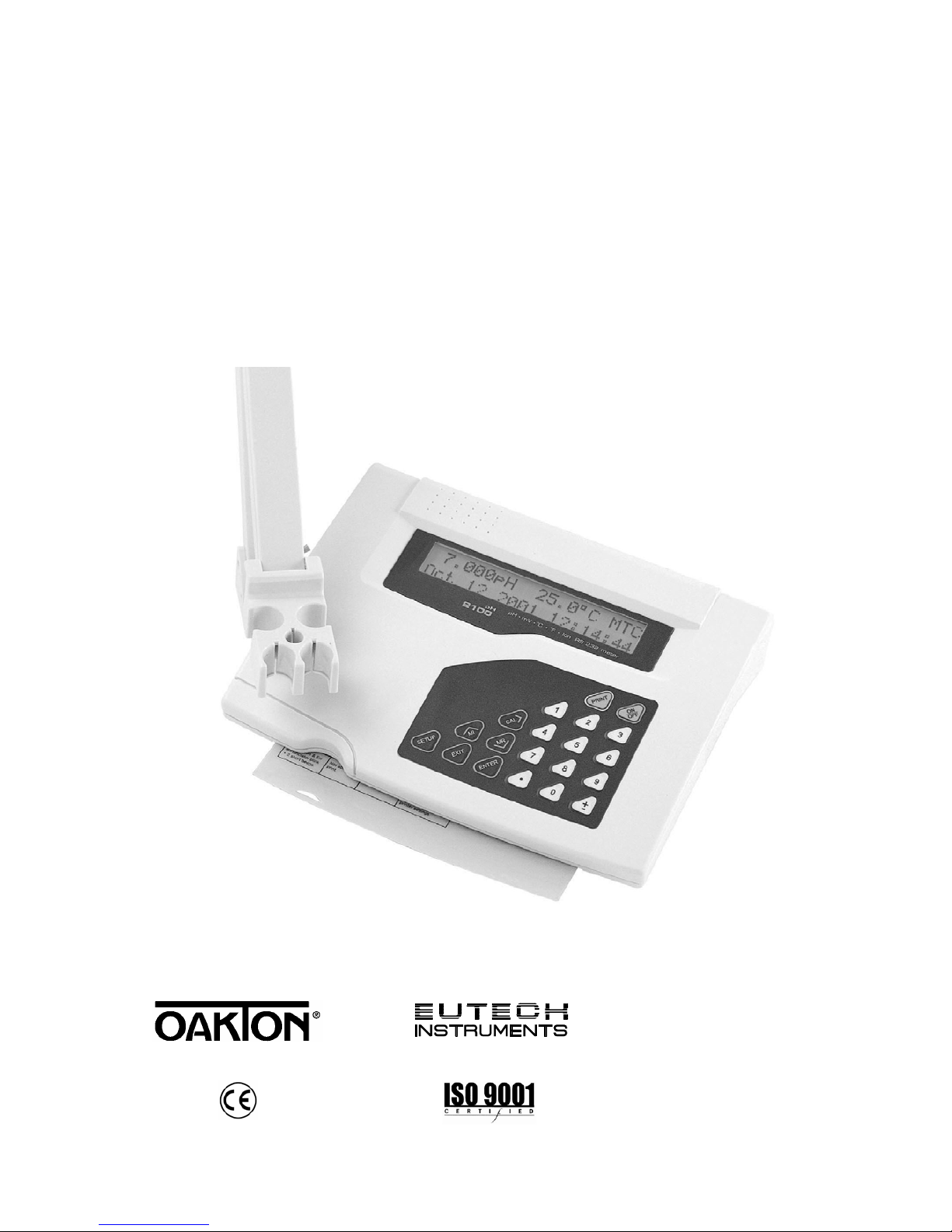
EUTECH INSTRUMENTS CYBERSCAN PH 1100 2100 PHION METER, pH 1100, pH 2100 Instruction Manual
Instruction Manual
pH 1100/ pH 2100
Bench pH/Ion Meter
Technolo
gyM
adeEa
sy...
68X090818
Rev. 3 07/03


Instruction Manual pH 1100/ 2100
PREFACE
Thank you for selecting the pH 1100/ 2100 benchtop meter. This meter measure pH, millivolts, relative millivolts and
temperature. The pH 2100 meter also measures ion concentration.
The instruction manual serves to explain the use of the pH 1100/ 2100 bench meter as a step-by-step operational guide
to help you familiarize with the meter’s features and functions. It is structured sequentially with illustration of diagrams
that explains the various functions and setup menus available.
This manual is written to cover as many anticipated applications and uses of the pH 1100/ 2100 Bench meter as
possible. If there are doubts in the use of the meter, please do not hesitate to contact the nearest Authorized Distributor
or Customer Service Dept. for assistance.
Eutech Instruments/ Oakton Instruments reserve the rights to change, make improvement and modify specifications
without prior notice and cannot accept any responsibility for damage or malfunction to the instrument caused by improper
use.
Copyright © 2002
Eutech Instruments Pte. Ltd.
Oakton Instruments
All rights reserved.
Rev. 3 07/03

Instruction Manual pH 1100/ 2100
TABLE OF CONTENTS
1 INTRODUCTION 6
1.1 Introducing the Bench Meter Series 6
1.2 Keypad 7
1.3 Rear Panel 8
1.4 Electrode Holder 9
2 STARTING UP 10
2.1 Back Panel Connections 10
2.2 Powering up and powering down 10
2.2.1 Powering up 10
2.2.2 Powering down 10
3 PH CALIBRATION & MEASUREMENT 11
3.1 pH calibration 11
3.1.1 Automatic Temperature Compensation (ATC) 11
3.1.2 Starting pH calibration 12
3.1.3 Standard pH buffer calibration 13
3.1.4 Custom pH buffer calibration 14
3.1.5 Calibration error messages 15
3.2 pH measurement 16
3.2.1 Automatic temperature compensation 16
3.2.2 Adjusting manual temperature compensation 16
3.2.3 Taking pH Measurements 17
4 mV CALIBRATION AND MEASUREMENT 18
4.1 mV Calibration 18
4.1.1 mV Calibration error message 18
4.2 mV Measurement 19
5 ION CALIBRATION AND MEASUREMENT (ONLY APPLICABLE FOR pH 2100) 20
5.1 Ion calibration 20
5.2 Ion calibration error messages 21
5.3 Ion measurement 22
6 MEMORY FUNCTIONS 23
6.1 Memory input 23
6.1.1 Manually storing a reading into memory 23
6.2 Memory recall 24
6.2.1 Recalling readings in manual recall mode 24
6.2.2 Recalling readings in automatic recall mode 24
7 STABILITY INDICATOR 25
8 ALARM FUNCTIONS 25
8.1 High and Low measurement alarm 25
8.2 Calibration due alarm 25
9 TEMPERATURE CALIBRATION 26
9.1 Temperature Calibration 26
9.2 Temperature Calibration Error Messages 26
10 SETUP MODE 27
10.1 Setup mode overview 27
10.1.1 pH/Temperature setup submenus 27
10.1.2 mV setup submenus 28
10.1.3 Ion setup submenus (pH 2100 only) 28
10.1.4 Meter general configuration setup submenus 29
10.2 pH/ temperature setup mode 30
10.2.1 Entering pH/temperature setup mode 30
10.2.2 pH buffer setup program P1.0 30
10.2.3 pH resolution setup program P1.1 31
10.2.4 Temperature unit setup program P1.2 31
10.2.5 pH Measurement Alarm Setup Program P1.3 32
10.2.6 pH Calibration Due Alarm Setup program P1.4 33
10.2.7 Stability Setup Program P1.5 34
10.2.8 View pH calibration data setup program P1.6 35

Instruction Manual pH 1100/ 2100
10.2.9 pH calibration data reset setup program P1.7 36
10.3 mV setup mode 37
10.3.1 Entering mV setup mode 37
10.3.2 mV measurement alarm setup program P2.0 38
10.3.3 mV calibration due alarm setup program P2.1 39
10.3.4 Stability setup program P2.2 40
10.3.5 View mV calibration data setup program P2.3 41
10.3.6 mV calibration data reset setup program P2.4 42
10.4 Ion setup mode (pH 2100 meter only) 43
10.4.1 Entering ion setup mode 43
10.4.2 Ion unit setup mode P3.0 43
10.4.3 Ion measurement alarm setup program P3.1 44
10.4.4 Ion calibration due alarm setup program P3.2 45
10.4.5 Stability setup program P3.3 46
10.4.6 Ion mode setup program P3.4 47
10.4.7 View ion calibration data setup program P3.5 48
10.4.8 Ion calibration data reset setup program P3.6 49
10.5 Meter general configuration setup mode 50
10.5.1 Entering meter general setup mode 50
10.5.2 Date/time setup mode P4.0 50
10.5.3 Backlight setup mode P4.1 51
10.5.4 Data log setup mode P4.2 52
10.5.5 Memory recall setup mode P4.3 52
10.5.6 Communication setup mode P4.4 53
10.5.7 Data transfer setup mode P4.5 53
10.5.8 Memory clear setup mode P4.6 54
10.5.9 Meter reset setup mode P4.7 54
11 ELECTRODE CARE 55
11.1 Electrode Activation 55
11.2 Electrode Maintenance 55
11.3 Storing pH/ORP electrodes 55
12 RS 232 COMMUNICATION 56
12.1 Using with printer 56
12.1.1 Sending data to printer 56
12.2 Using with computer 56
13 ADDITIONAL INFORMATION 57
13.1 pH and Temperature 57
13.2 pH Buffer Calibration Solution 57
13.3 Standard pH Buffers 57
14 SUMMARY OF DEFAULT SETTINGS / OPTIONS 58
15 TROUBLESHOOTING & ERROR MESSAGES 59
16 SPECIFICATIONS 60
17 ACCESSORIES 61
18 WARRANTY 62
Instruction Manual pH 1100/ 2100
6
1 INTRODUCTION
1.1 Introducing the Bench Meter Series
The pH 1100/ 2100 bench meter is microprocessor-based which incorporates new ASIC (Application Specific Integrated
Circuit). It is designed with convenience in mind and offers many advanced, user-friendly features. The meters are
capable of storing and recalling up to 100 data sets in its non-volatile memory. In addition, as a space saver, an optional
swivel electrode holder can be attached at the either side of bench meter for resting the electrodes and probes during
operation.
The pH 1100/ 2100-- bench meter measures pH, millivolts, relative millivolts and temperature. The pH 2100 meter also
measures ion concentration. These meters are equipped with a large customized LCD (Liquid Crystal Display) with
simultaneous display of the measured values for easy reading. It is most ideal for routine pH/Ion Concentration
measurement in indoor applications.
Instruction Manual pH 1100/ 2100
7
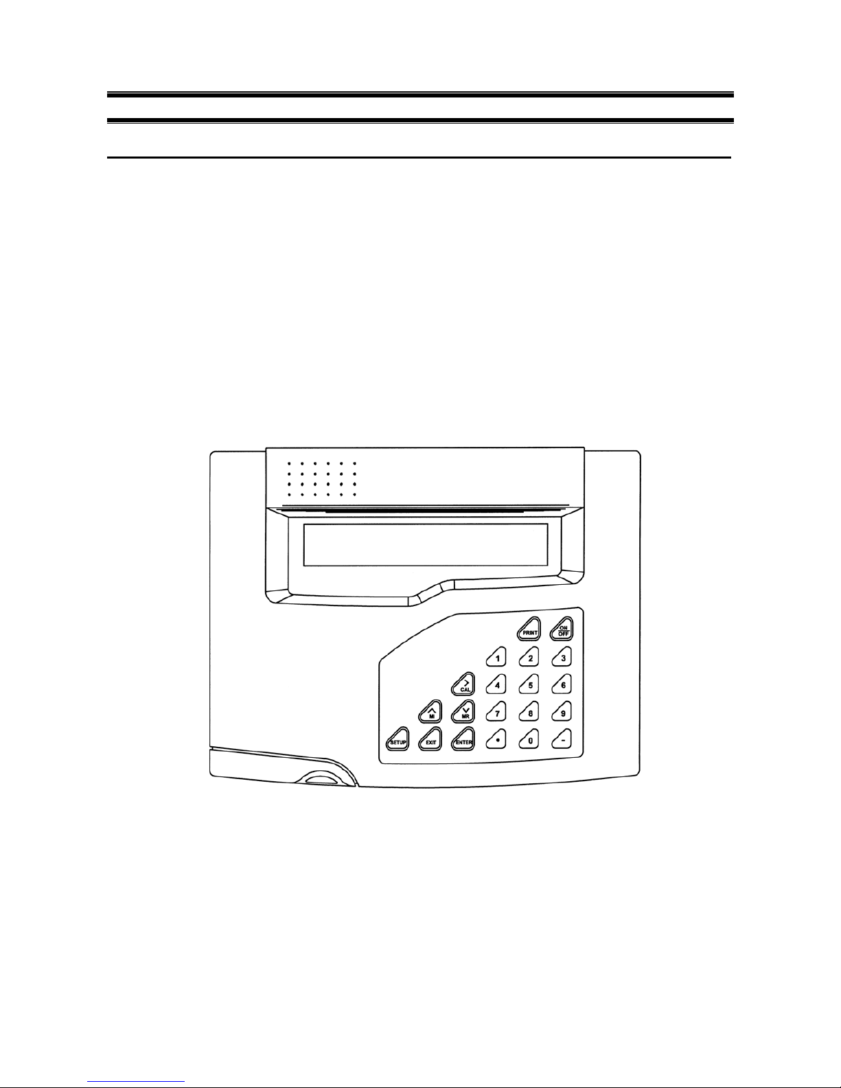
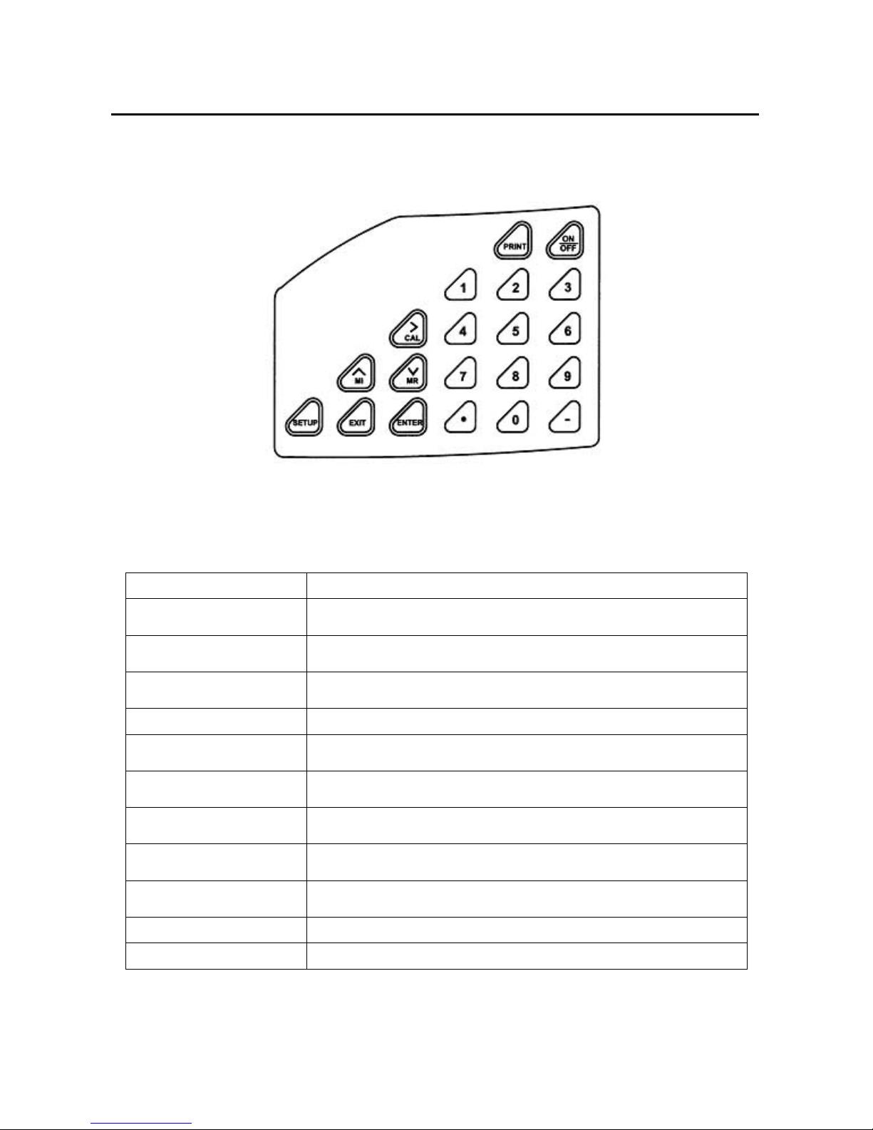
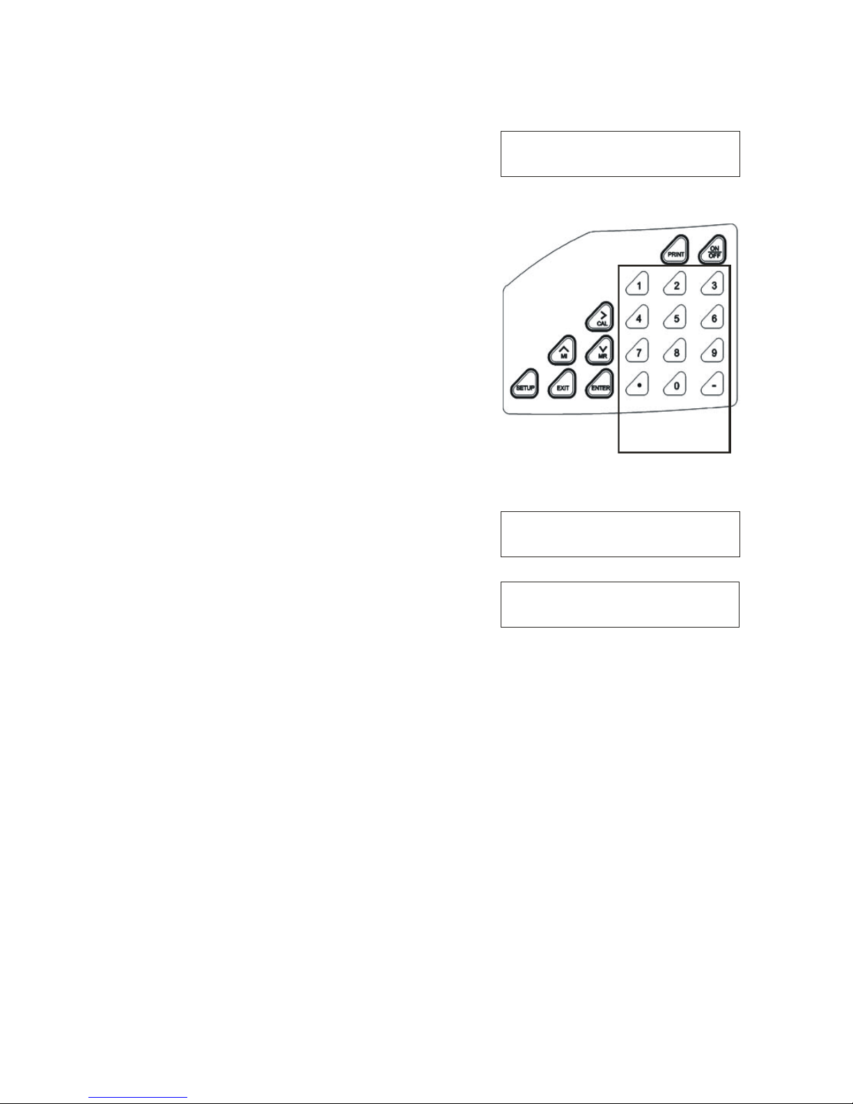
1.2 Keypad
See Figure 1.
A large membrane keypad with touch feedback makes the meter easy to use. Names and symbols describe the function
button controls.
Figure 1: Membrane Keypad
ON/OFF
Power meter On or Off
ENTER
Confirm selection in all modes of operations;
Scroll through the sub-menus program in the SETUP modes
EXIT
Exit from current modes of operations;
Exit from calibration mode after 3
rd
point calibration (for pH/Ion)
CAL / ¾
Enter into calibration modes of the meter;
Select or scroll to the next options available
MODE
Select the measurement modes:- pH, Ion Concentration, mV, Relative mV
HOLD
Freeze the displayed value; allow you to print the held reading or store it into
memory
SETUP
Enter SETUP mode of the meter for customization of meter functions as well as
view some diagnostic functions (refer to the table for details of SETUP menus)
¿/ MI
Store the displayed value into memory;
Increment values or scroll through the next options available
À/ MR
Recall stored values from the memory in the Last-In-First-Out (LIFO) sequence;
Decrement values or scroll through the next options available
PRINT
Send measured data being measured or data stored in the memory to a
peripheral device via the RS232C port of meter
Numeric Keys (0-9 & .)
Enter numeric values and decimal point at appropriate places
- (Minus)
Enter negative sign at appropriate places
Instruction Manual pH 1100/ 2100
8
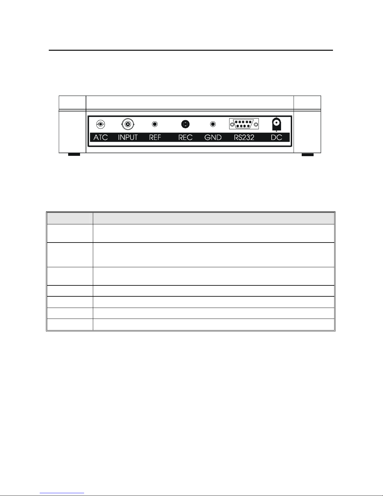
1.3 Rear Panel
See Figure 2.
The pH 1100/ 2100 meters provide a complete set of input connections for the various accessories commonly used.
Listed in the table below are details of the connections that you can make.
Connector Function
ATC For phono jack connection from the temperature probe for Automatic Temperature Compensation.
The probe should be a 30KΩ thermistor probe.
INPUT For connecting sensors with a BNC connector to the meter. The meter accepts any pH, ORP or ISE
electrode with a BNC connector. Always make sure that the connector is clean and dry.
REF For connection to the pin tip type reference electrode normally used with half cell (mono) type pH or
ISE electrodes.
REC For connection to the strip chart recorder.
GND For connection to the ground earth jack (standard pin tip connectors).
RS232 For connection to the RS232C serial port.
DC For connection of the AC adapter power supply (included).
Figure 2: Rear View of Meter
Instruction Manual pH 1100/ 2100
9
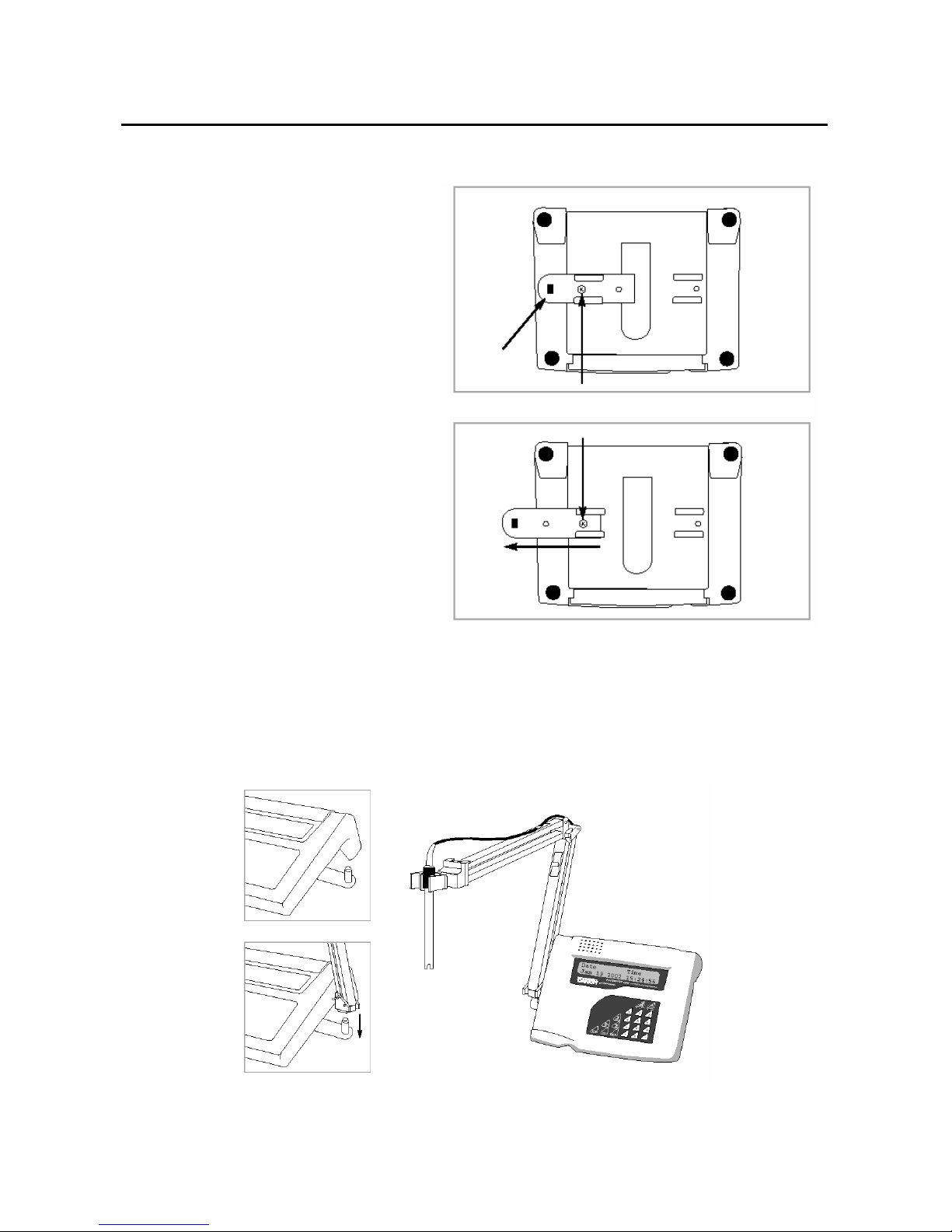
1.4 Electrode Holder
The electrode holder is included in the same box as the meter.
To attach the electrode holder to the meter:
1. The electrode holder base attached to the
bottom of the meter comes in the shipping
position. See Figure 3.
2. Use a Phillips screwdriver to remove the
screw holding the electrode holder in
shipping position. See Figure 3.
3. Slide the electrode base away from the
meter until the second screw slot lines up
with the original screw hole. Use the screw
removed earlier to secure electrode holder
base into position. See Figure 3.
4. The electrode holder arm is reversible. If
desired, remove screw holding electrode
holder base and slide base out of brackets.
Slide base into brackets on opposite side
and replace screw.
5. To install the electrode arm, turn meter back
to the upright position. See Figure 4.
6. Line up the hole on the base of the
electrode holder arm with the peg on the
electrode holder base. Slide the hole
securely onto the electrode holder base.
See Figure 4.
7. The electrode arm is now ready to swing
into desired position.
Figure 3: Bottom of Meter
Figure 4: Fix electrode holder arm to holder base
Instruction Manual pH 1100/ 2100
10
2 STARTING UP
Attention: Do not get water on the BNC connector during operation.
Avoid touching the connector with soiled or wet hands.
2.1 Back Panel Connections
Refer back to Figure 2. Make the necessary connections as mentioned in Section 1.3 Rear Panel, pg 8.
2.2 Powering up and powering down
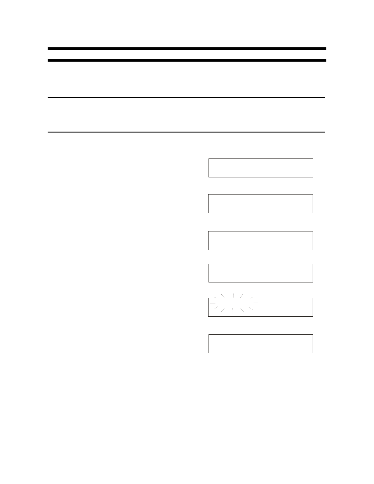
2.2.1 Powering up
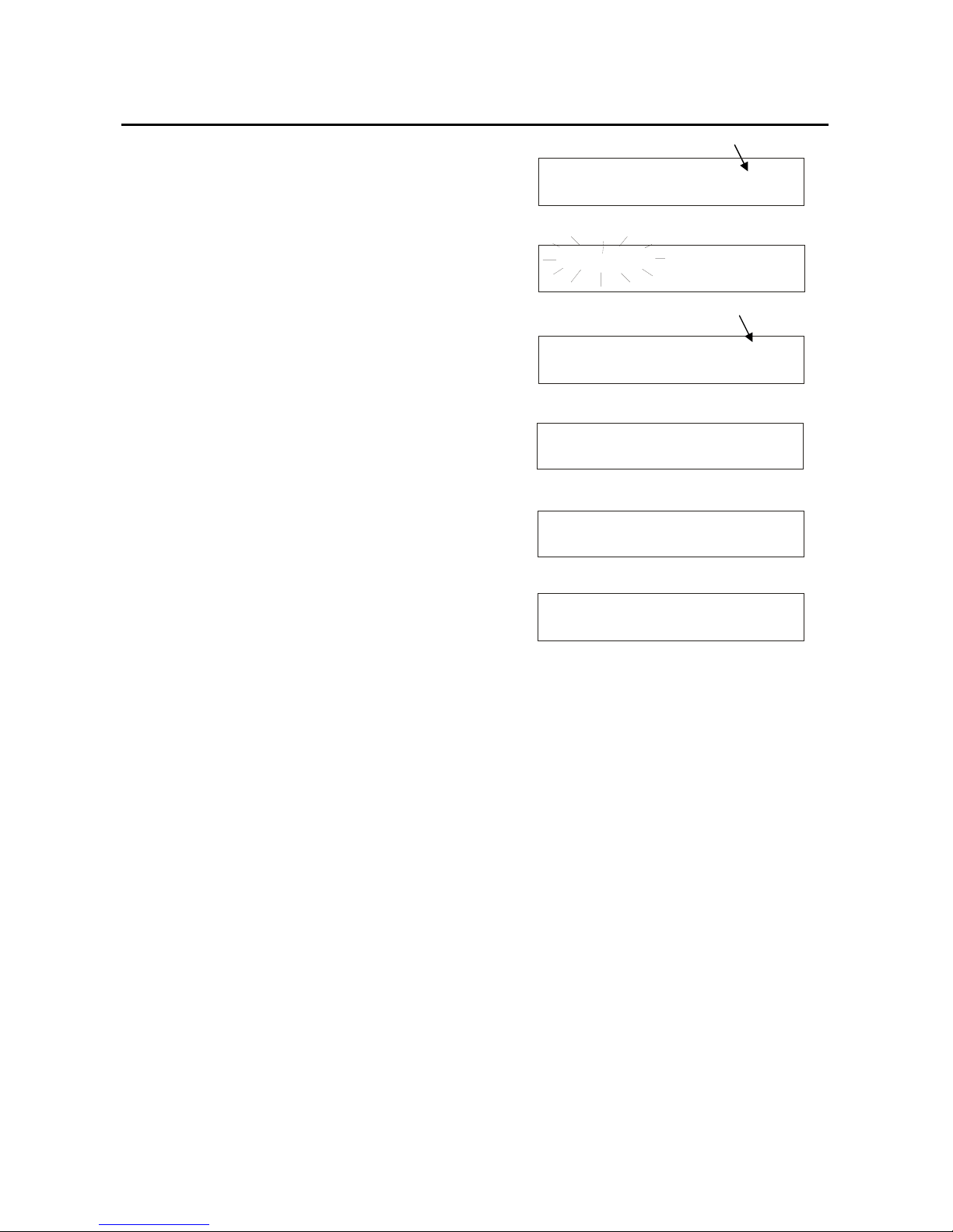
1. When first connected to the power supply, the meter runs a
self test, the display flashes Hardware Testing... Status:
Pass.
See Figure 5.
2. It then displays current date and time. See Figure 6. This
display will also appear when the meter is turned off while
still connected to the power supply. See Figure 6.
3. See Figure 7. To turn the meter on press ON/OFF. The
upper display flashes Bench pH/Ion 2100 for the pH 2100,
(Display flashes Bench pH 1100 for the pH 1100 meter.)
and then the lower display flashes SW Rev 1.20. See
Figure 7.
4. The display flashes System Initializing, Please wait...
See Figure 8.
5. If this is the first power up since the power was connected,
you must indicate desired measurement mode. Use >/CAL
to select. The mode selected will flash. See Figure 9.
Press ENTER to confirm. The meter then enters
measurement mode.
6. After initial startup, the meter will automatically return to
the measurement mode previously selected as long as
power connection is maintained.
2.2.2 Powering down
1. To turn the meter off press ON/OFF. The display flashes
System Shutting Down, Please wait... See Figure 10.
Then, the date and time display will appear. See Figure 6.
The date and time will continue to display until the power
supply is disconnected.
Hardware Testing. . . .
Status: Pass
Date Time
Jan 25 2002 09:09:30
System Initializing
Please wait. . .
pH/Temp mV Ion
Select & Press ENTER
Fig ure 5
Fig ure 6
Fig ure 7
Fig ure 8
Fig ure 9
Fig ure 10
Bench pH/Ion 2100
SW Rev 1.20
System Shutting Down
Please wait. . .
Instruction Manual pH 1100/ 2100
11
3 PH CALIBRATION & MEASUREMENT
3.1 pH calibration
This meter is capable of up to 5 point calibration with selectable buffer sets (USA, NIST, Bf1, Bf2 or any 5 custom buffers
of your choice). The meter retains stored pH calibrations even when turned off. For best accuracy, we recommend that
you perform at least a 2-point calibration using buffers that bracket (one above and one below) the expected sample
range. A single point cal is possible only at the offset points namely 7.00 or 6.86. For custom buffer sets, you must
perform at least a 2 point calibration.
Selectable buffer sets:
USA: 1.68, 4.01, 7.00, 10.01, 12.45
NIST: 1.68, 4.01, 6.86, 9.18, 12.45
Bf1: 1.68, 4.01, 6.86, 10.01, 12.45
Bf2: 1.68, 4.01, 7.00, 9.18, 12.45
Any 5 user selected custom buffers
To select which buffer sets you wish to use see Section 10.2.2: Program pH Buffer Setup: P1.0 in the pH/Temp setup
mode (page 30).
When you recalibrate your meter, old pH calibration points are replaced on a point by point basis. For example, if you
previously calibrated your meter at pH 4.01, 7.00, and 10.01, and you recalibrate at pH 7.00, the meter retains the old
calibration data at pH 4.01 and pH 10.01. To view current calibration points, see Section 10.2.8: Program pH Cal Data
P1.6 in the pH/Temp setup mode (page 35).
If you choose to recalibrate to only 1 or 2 pH values, the older calibration values you do not calibrate to will remain stored.
These old stored calibration values may cause accuracy loss when your readings are close to the old values. To clear old
calibration data, reset the meter as shown in Section 10.2.9 Program pH Cal Reset: P1.7 in the pH/Temp setup mode
(page 36).
3.1.1 Automatic Temperature Compensation (ATC)
If you will be taking pH measurement using Automatic Temperature
Compensation (ATC), you must perform your pH calibration with
ATC temperature probe attached. Attach the temperature probe to
the rear of the meter. The ATC mode annunciator shows on the
display. See Figure 11. Insert the probe into the pH buffer solution
along with your pH electrode.
If manual temperature compensation is preferred, do not plug a
temperature probe into the meter. The MTC mode annunciator
shows on the display. See Figure 12. The default manual
temperature compensation is 25.0°C. To change the manual
temperature compensation default, see Section 9 Temperature
Calibration for instructions (page 26).
7.179pH 25.3 C ATC
Jan 18 2002 08:46:25
°
7.179pH 25.3 C MTC
Jan 18 2002 08:46:25
°
Figure 11
Figure 12

Instruction Manual pH 1100/ 2100
12
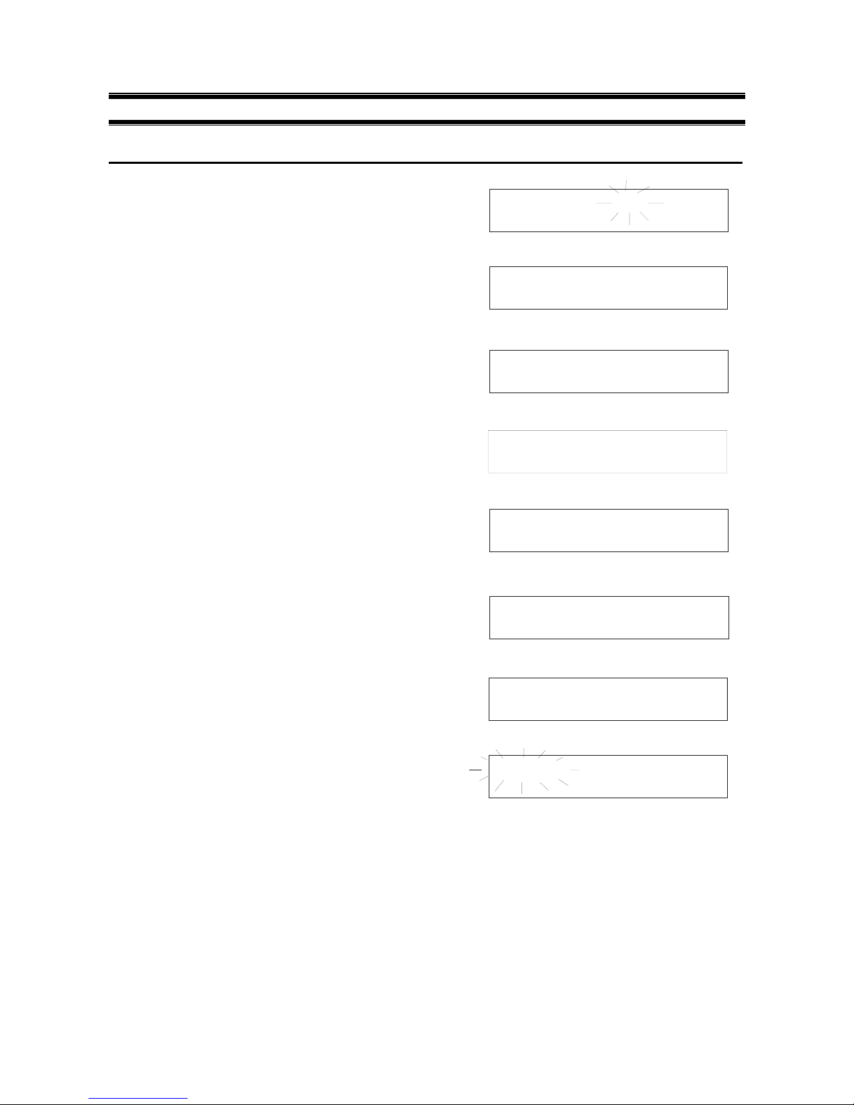
3.1.2 Starting pH calibration
1. Turn the meter ON. If the meter is not in the pH measurement
mode, press EXIT and press >/CAL to select pH/Temp. The
mode selected will flash. See Figure 13. Press ENTER to
confirm selection. The meter is now in pH measurement mode.
See Figure 14.
2. Rinse the electrode in deionized water or rinse solution. If using
the ATC function with a separate temperature probe, rinse the
temperature probe as well. Do not wipe the pH electrode or
temperature probe dry. Wiping the probes causes static, and
will create calibration and measurement instability.
3. Select pH buffer and pour into a clean container.
4. Dip the electrode and ATC probe into the calibration buffer. The
end of the probes must be completely immersed into the
sample. Stir probes gently to create a homogeneous sample.
5. Press >/CAL to enter the pH calibration mode. The display
flashes Cal Mode Activated, Please wait....
See Figure 15. The meter is now in pH calibration mode.
The meter automatically recognizes the buffers in the set you have selected in the SETUP mode. If you wish to change
the buffer set selected, see Section 10.2.2, Program pH Buffer Setup: P1.0 in the pH/Temp setup mode (page 30).
If your meter is set up for standard buffers (USA, NIST, Bf1, Bf2), proceed to Section 3.1.3: Standard pH buffer
calibration (page 13). If your meter is set up for custom buffers, proceed to Section 3.1.4: Custom pH buffer calibration
(page 14).
Figure 13
Figure 14
Figure 15
pH/Temp mV Ion
Select & Press ENTER
7.179pH 25.3 C ATC
Jan 18 2002 08:46:25
°
Cal Mode Activated
Please wait. . .

Instruction Manual pH 1100/ 2100
13
3.1.3 Standard pH buffer calibration
1. When entering the standard calibration mode, the first buffer
calibration point for standard pH buffers is 7.000 or 6.860
(depending upon which pH buffer set is selected). The upper
display shows the current reading, the lower display will show
Auto Buf Scan: 7.000 (or 6.860). The upper display will flash pH
until the reading has stabilized. See Figure 16. If the selected
buffer value is not within ±1.0 of the measured pH value, the
Auto pH Scan will continue to change until the pH buffer is
within ±1.0.
2. When pH reading has stabilized, press ENTER. The lower
display flashes *pH Offset Cal Done. See Figure 17. This
calibration point is now stored in the meter.
• If you are performing a one-point calibration, press EXIT.
The screen flashes Sys Updating...Please wait....The meter
then returns to the pH measurement mode. You may now
start taking pH readings.
• If you are performing a multi-point calibration, go to step 3.
3. Rinse the probe with deionized water or a rinse solution, and
place it in the next pH buffer. The lower display automatically
scans to the next pH buffer solution.
4. Wait for the measured pH value to stabilize. The upper display
will flash pH until the reading has stabilized.
5. When pH reading has stabilized, press ENTER. The lower
display flashes 2 Point Cal Done * (3 if you have calibrated 3
points,4 if 4 points, etc.). See Figure 18. This calibration point is
now stored in the meter. Repeat steps 3-5 for each point you
wish to calibrate. When you are finished calibrating, press EXIT.
The screen flashes Sys. Updating... Please wait.... The meter
then returns to the pH measurement mode. You may now start
taking pH readings.
6. If you perform a complete 5-point pH calibration, when you
calibrate the fifth point and press ENTER, the meter
automatically returns to measurement mode. You may now start
taking pH readings.
NOTE:
To exit from pH calibration mode at any point without confirming calibration, DO NOT press ENTER in steps 2, 5 or 6.
Press EXIT instead. If EXIT is press before a 1-point calibration is performed the upper display flashes Error: Cal Aborted .
See Figure 19.
DO NOT REUSE SOLUTIONS AFTER CALIBRATION.
Contaminants in the solution can affect the calibration, and eventually the accuracy of the measurements.
Figure 16
Figure 17
Figure 18
Figure 19
7.001pH 25.4 C ATC
Auto Buf Scan: 7.000
°
7.001pH 25.4 C ATC
pH Offset Cal Done
°
*
Error: Cal Aborted
10.010
2 Point Cal Done
*
pH 25.4 C ATC
°
Instruction Manual pH 1100/ 2100
14
3.1.4 Custom pH buffer calibration
1. When entering the custom calibration mode, the lower display
will show Key In Std:. The upper display shows the pH buffer the
electrode is dipped into. The lower display will show the same
value as the upper display only if the meter has not been
calibrated or if the meter has been reset. See Figure 20. If the
meter has previously been calibrated, the lower display will
toggle to the stored calibration point that is closest to current
buffer value.
2. Using the numeric keypad (See Figure 21), enter the value of
the first custom pH buffer. If you make a mistake, use the ∆/MI
or ∇/MR to highlight mistake, then retype.
3. Press ENTER when first custom pH buffer is keyed in. The
display will read 1 Point Cal Done *. See Figure 22.
NOTE: In the custom pH buffer calibration mode you must
perform at least a 2-point calibration, if you press EXIT before
you calibrate at 2 points the screen will flash Error: Cal Aborted
(See Figure 23) and will return to the pH measurement mode
without confirming any calibration points.
4. Rinse the probe with deionized water or a rinse solution, and
place it in the next custom pH buffer. The lower display will
show Key In Std: The upper and lower displays show the pH
buffer value.
5. Enter the value of the next custom pH buffer. Press ENTER
when done. The display will read 2 Point Cal Done *. If you are
performing a 2-point calibration, press EXIT. The screen flashes
Sys Updating...Please wait... The meter then returns to the pH
measurement mode. You may now start taking pH readings.
• If you are performing a 3, 4 or 5-point calibration go to step
6.
6. Repeat steps 4 and 5 for each additional custom buffer. Upon
confirmation of pH buffer, the display will read 3 Point Cal Done
* (4 if you have calibrated points, etc). When you have finished
calibrating desired number of points, press EXIT. The screen
flashes Sys. Updating... Please wait...
The meter then returns to the pH measurement mode. If you
have entered 5 calibration points, the meter will automatically
return to pH measurement mode. You may start taking pH
readings.
NOTE:
To exit from pH calibration mode at any point without confirming calibration, DO NOT press ENTER in steps 3 or 5. Press
EXIT. If EXIT is pressed before a 2-point calibration is performed the upper display flashes Error: Cal Aborted. See
Figure 23.
DO NOT REUSE SOLUTIONS AFTER CALIBRATION.
Contaminants in the solution can affect the calibration, and eventually the accuracy of the measurements.
Figure 20
Figure 21
Figure 22
Figure 23
7.179pH 25.3 C ATC
Key In Std: 7.179
°
Error: Cal Aborted
7.179pH 25.3 C ATC
1
°
Point Cal Done *
Num e r i c K e ypad
7.179pH 25.3 C ATC
Key In Std: 7.179
°
7.179pH 25.3 C ATC
1 Cal Point Done °*

Instruction Manual pH 1100/ 2100
15
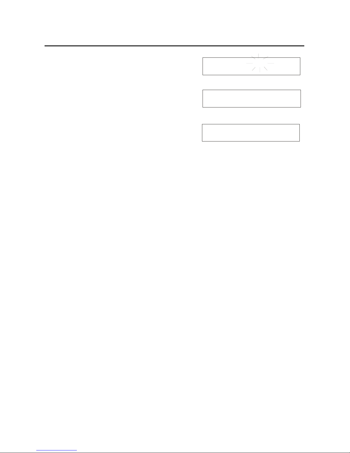
3.1.5 Calibration error messages
Standard pH Buffer Calibration:
If the first buffer value of 7.000 or 6.860 is off by more than ±1.0,
the upper display will flash Error: and the lower display will read
pH Offset Error. See Figure 24. Press EXIT to clear error
message and return to pH measurement mode.
If any other pH buffer point is off by more than ±1.0, the upper
display will flash Error: and the lower display will read pH Slope
Error. See Figure 25. Press EXIT, to clear error message and
return to pH measurement mode.
Custom pH Buffer Calibration:
If the each custom pH buffer value is not within ±1.0 pH of the
keyed in value, the upper display will flash Error: and the lower
display will read Too much offset @7pH. See Figure 26. Press
EXIT to clear error message and return to pH measurement
mode.
If the slope is not within 75% to 105%, the upper display will
flash Error: and the lower display will read Slope out: 75% -
105%.
See Figure 27. Press EXIT to clear error message and return to
pH measurement mode.
If adjacent calibration points are less than ±1.0 pH apart, the
upper display will read Error: Pts too close, and the lower display
will read OR slope diff. sign. See Figure 28. Press EXIT to clear
error message and return to pH measurement mode.
/measurement
Fig ure 24
Fig ure 25
Fig ure 26
Fig ure 27
Fig ure 28
Error :
pH Offset Error*
Error :
pH Slope Error*
Error :
Too much Offset @7
Error :
Slope out:75% - 105%
Error :Pts too close
Or slope diff. sign
Instruction Manual pH 1100/ 2100
16
3.2 pH measurement
This meter is capable of taking measurements with automatic or
manual temperature compensation. Automatic Temperature
Compensation (ATC) occurs when a temperature sensor is
plugged into the meter. If there is no temperature sensor
plugged into the meter, the default setting is automatically 25°C
(if the meter has never been manually set for temperature) or the
last manually set value. You can manually set the temperature to
match your working conditions using a separate thermometer.
3.2.1 Automatic temperature comp ensation
For automatic temperature compensation, simply plug the
temperature probe into the meter (see page 8). The ATC
indicator will light on the LCD. See Figure 29.
NOTE: If you are using a temperature probe, the probe must be
submersed in the liquid you are measuring.
3.2.2 Adjusting manual temp erature compensation
IMPORTANT: For manual compensation, you must disconnect
the temperature probe.
1. Turn the meter ON. If the meter is NOT in the pH
measurement mode, press EXIT and use >/CAL to select
pH/Temp. The mode selected will flash. See Figure 30.
Press ENTER to confirm selection. The meter is now in pH
measurement mode. If the temperature probe is
disconnected, the upper display will indicate MTC. See
Figure 31.
2. Press >/CAL to enter pH/Temp calibration mode. The
display will flash Cal Mode Activated, Please wait... Press
>/CAL key again to enter the temperature calibration mode.
The display will flash Temperature Cal Mode.
(Please
remove this gap. The copy should follow as one.)See
Figure 32. The upper display then reads MTC Temp:
25.0°C and the lower display reads Key In Std: 25.0°C. See
Figure 33.
3. Check the temperature of your sample using an accurate
thermometer.
4. Key in the temperature value using the numeric keypad. If
you make a mistake, use the ∆/MI or∇/MR key to highlight
mistake, then re-enter.
5. Press ENTER to confirm temperature and to return to the
pH measurement mode. Display will flash Temp Cal
Complete in the upper display and MTC Set Temp:
(temperature that was keyed in). See Figure 34. The display
will flash Sys. Updating...Please wait... The meter then
returns to pH measurement mode and will now compensate
pH reading with the manually set temperature.
NOTE: To exit this program without confirming the manual
temperature compensation value, do not press ENTER in step 5.
Press EXIT instead. The display will flash Error: Cal Aborted and
meter will return to pH measurement mode.
pH/Temp mV Ion
Select & Press ENTER
7.179pH 25.3 C ATC
Jan 18 2002 08:46:25
°
Figure 29
Figure 30
Figure 31
Figure 32
Figure 33
Figure 34
Temperature Cal Mode
MTC Temp : 25.0 C
Key In Std: 25.0 C
°
°
7.179pH 25.3 C MTC
Jan 18 2002 08:46:25
°
Temp Cal Complete
MTC Set Temp: 26.5 C
°

Instruction Manual pH 1100/ 2100
17
3.2.3 Taking pH Measuremen t s
NOTE: Be sure to remove the electrode soaker bottle or
protective rubber cap on the electrode before measurement.
1. Rinse the probe with deionized or distilled water before use
to remove any impurities adhering to the probe body. If the
pH electrode dehydrated, soak it for 30 minutes in electrode
storage solution or a 2M to 4M KCl solution.
2. Press ON. The upper display shows current pH reading and
temperature, and indicates automatic or manual
temperature compensation. The lower display shows month,
date, year and time. See Figure 35.
3. Dip the probe into the sample. Make sure the sensor or the
glass bulb of the electrode is completely immersed into the
sample. Stir the probe gently to create a homogenous
sample.
4. Allow time for the reading to stabilize. The pH indicator
blinks when reading is not stable. See Figure 36. When the
readings stabilizes, the pH indicator freezes and no longer
blinks.
7.179pH 25.3 C ATC
Jan 18 2002 08:46:25
°
Figure 35
Figure 36
7.546pH 25.4 C ATC
Jan 18 2002 08:46:30
°
Instruction Manual pH 1100/ 2100
18
4 mV CALIBRATION AND MEASUREMENT
4.1 mV Calibration
1. Turn the meter ON. If the meter is not in the mV
measurement mode, press EXIT and use >/CAL to select
mV. The mode selected will flash. See Figure 37. Press
ENTER to confirm selection. The meter is now in absolute
mV measurement mode. See Figure 38.
2. Rinse the electrode in deionized water or rinse solution.
Do not wipe the electrode dry. Wiping the probes
causes static, and will create calibration and
measurement instability.
3. Select your standard and pour into a clean container.
4. Dip the probe into the standard. The end of the probe
must be completely immersed into the sample. Stir the
probe gently to create a homogeneous sample.
5. Press >/CAL key to enter the mV calibration mode. The
display will read Cal Mode Activated, Please wait... See
Figure 39. The meter is now in mV calibration mode. The
upper display shows Abs. mV: and lower display shows
Key in Std: See Figure 40.
NOTE: In mV calibration, the value shown in the upper
display is the same as the lower display.
6. Key in the mV value to match the standard value using
the numeric keypad. If you make a mistake, use the ∆/MI
or ∇/MR to highlight mistake, then re-enter.
7. Press ENTER key to confirm the reading. The display
flashes mV Cal Completed, mV Offset: (shows the mV
offset value). See Figure 41. It then flashes Sys
Updating... Please wait.... The meter returns to mV
measurement mode. The upper display now reads Rel.
mV. See Figure 42.
NOTE: New mV calibrations will override existing the stored
mV calibration data. The meter retains stored mV calibrations
even when the meter is turned off.
To exit from mV calibration mode at any point without
confirming calibration, DO NOT press ENTER in step 7. Press
EXIT.
The upper display then flashes Error: Cal Aborted.
See Figure 43.
4.1.1 mV Calibration error message
If the offset adjustment of your mV calibration is not within ±150.0 mV; the upper display will flash Error: and the lower
display will read mV Offset too large. See Figure 44. Press EXIT to clear error message and return to mV measurement
mode.
pH/Temp mV Ion
Select & Press ENTER
Rel. mV : 200.0mV
Jan 20 2002 20:34:45
Abs. mV : 226.9mV
Jan 20 2002 20:30:05
Figure 37
Figure 38
Figure 39
Figure 40
Figure 41
Figure 42
Figure 43
Figure 44
Cal Mode Activated
Please wait. . .
Error: Cal Aborted
Abs. mV : 226.9mV
Key In Std: 226 . 9 mV
mV Cal Completed
mV Offset: -3.7 mV
Error :
mV Offset too large
Instruction Manual pH 1100/ 2100
19
4.2 mV Measurement
1. Turn the meter ON. If the meter is NOT in the mV
measurement mode, press EXIT and use >/CAL to select mV.
The mode selected will flash. See Figure 45. Press ENTER to
confirm selection.
The meter is now in Rel mV measurement mode. See Figure 46. If
you have not performed a mV calibration or have reset the meter,
the display will read Abs. mV. See Figure 47.
2. Dip the electrode into the sample. The sensor or glass bulb of
the electrode must be completely immersed into the sample.
Stir the electrode gently to create a homogeneous sample.
3. Allow time for the reading to stabilize. The upper display will
show the mV reading, and the lower display will show the
current month, day and time. See Figure 46.
pH/Temp mV Ion
Select & Press ENTER
Rel. mV : 200.0mV
Jan 20 2002 20:34:45
Abs. mV : 226.9mV
Jan 20 2002 20:30:05
Figure 45
Figure 46
Figure 47
Instruction Manual pH 1100/ 2100
20
5 ION CALIBRATION AND MEASUREMENT (ONLY APPLICABLE FOR pH 2100)
The pH 2100 meter reads ion concentration in ppm, ppt, mg/l, g/l, mmol/l and mol/l units. See Ion setup Program P3.0
(page 43) to select ion concentration units.
5.1 Ion calibration
This instrument is capable of up to 5-point custom ion calibration with a minimum of 2-point calibration. Custom
calibration values can be any value between 0.001 and 19998. Once the first calibration value is keyed in, all other
calibration will automatically be at least one decade apart.
For example if your first calibration point is at 0.001, all other calibration points will be at least one decade apart from
0.001 (0.001, 0.01, 0.1,1.0, 10.0, 100, 1000, 10000).
For best accuracy calibrate your meter to points with similar concentrations to the solutions you want to test.
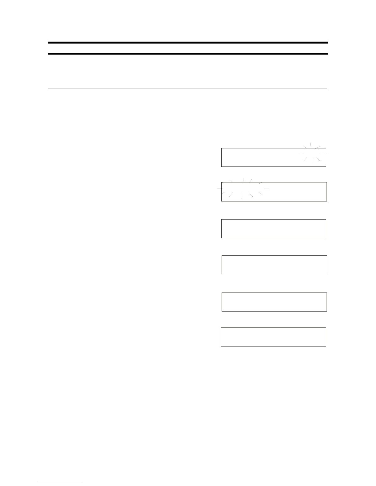
1. Connect an Ion Selective Electrode (ISE) to the BNC input
connector on the back of the meter.
2. Turn the meter ON. If the meter is not in the Ion measurement
mode, press EXIT and use >/CAL to select Ion. The mode
selected will flash. See Figure 48. Press ENTER to confirm
selection. The meter is now in Ion measurement mode.
3. If the meter has not been calibrated or has been reset, the
display will flash Ion Meas and current mV value. See Figure
49. If the meter has been calibrated previously, the display will
show the current concentration value plus the absolute mV
produced by the electrode.
4. Dip the electrode into the first calibration standard. Start with
the calibration standard that has the lowest concentration and
move up to higher concentration standards.
5. Press >/CAL to enter the ion calibration mode. The display will
flash Cal Mode Activated, Please wait... See Figure 50. The
display then shows Ion Conc: ppm (or unit selected in ion
setup mode) in the upper display and Abs. mV: in the lower
display. See Figure 51.
6. The first calibration point must be keyed in by the user. Key in
the concentration value of the standard using the numeric
keypad. If you make a mistake, use the ∆/MI or ∇/MR keys to
highlight mistake, then re-enter.
7. Press ENTER to confirm the first calibration point. T he display
will flash 1 Cal Point Done *, then the meter proceeds to the
next calibration point at least 1 decade apart from the first
calibration point. See Figure 52.
8. Use ∆/MI or ∇/MR keys to move the cursor to next calibration
point. All points will be a decade apart from the first calibration
point.
9. Rinse off the electrode with deionized water before placing it
in the next calibration standard.
10. Allow probe to stabilize in calibration standard. Press ENTER
to confirm. The display flashes 2 Point Cal Done *. See
Figure 53.
The meter proceeds to the next calibration point.
pH/Temp mV Ion
Select & Press ENTER
Cal Mode Activated
Please wait. . .
Ion Meas 160.3mV
Jan 20 2002 21:54:34
Figure 48
Figure 49
Figure 50
Figure 51
Figure 52
Figure 53
Ion Conc: ppm
Abs. mV : 100.7mV
Ion Conc: ppm
Abs. mV : 100.7mV
Ion Conc:0.01ppm
1 Point Cal Done
*
Ion Conc:0.10ppm
2 Point Cal Done
*
 Loading...