

Page 1
Instruction Manual
CyberScan pH 10 & pH 100
Hand-held pH / mV / Temperature / RS 232 Meter
68X007106
09/2001 rev 4
pH 10 Meter
pH/mV/°C
pH 100 Meter
pH/mV/°C/RS 232
Technology Made Easy ...
Page 2

PREFACE
This manual serves to explain the use of the Standard CyberScan series hand-held meters. The
models covered are the CyberScan pH 10 and the CyberScan pH 100 hand-held meters.
The manual functions in two ways, firstly as a step by step guide to help the user operate the
meter. Secondly, it serves as a handy reference guide.
This instruction manual is written to cover as many anticipated applications of the CyberScan pH
meters as possible. If there are doubts in the use of the CyberScan pH 10/100 meters, do not
hesitate to contact the nearest Eutech Instruments Authorized Distributor.
Eutech Instruments cannot accept any responsibility for damage or malfunction to the meter
caused by improper use of the instrument.
Remember to fill in the guarantee card and mail it back to your authorized distributor or Eutech
Instruments Pte Ltd (address, contact details, email and homepage information are found on the
back page of this manual).
The information presented in this manual is subject to change without notice as improvements are
made, and does not represent a commitment on the part of the Eutech Instruments Pte Ltd.
Note: Lotus® 1-2-3 is a registered trademark of Lotus Corporation.
Excel ® is a registered trademark of Microsoft Corporation.
Copyright ©1993 Eutech Instruments Pte. Ltd. All rights reserved.
Revised in September 2001, revision 4 (version 5).
Page 3

TABLE OF CONTENTS
1 INTRODUCTION 1
2 DISPLAY AND KEYPAD FUNCTIONS 2
2.1 Display 2
2.2 Keypad 3
3 PREPARATION 5
3.1 Inserting the Batteries 5
3.2 Connecting the pH Electrode, Temperature Probe & Electrode Holder 6
3.3 Connecting the AC/DC Adapter 8
3.4 Connecting the RS232C Cable (Only For CyberScan pH 100) 9
4 CALIBRATION 11
4.1 Preparing the Meter for Calibration 11
4.2 pH Calibration with ATC 12
4.3 pH Calibration (without ATC) 14
4.4 Temperature Calibration 15
4.5 Calibration Procedure for Relative mV Measurements (For pH 100 Only) 17
4.6 Erasing Calibrated Values (For pH 100 only) 18
5 MEASUREMENT 19
5.1 Automatic Temperature Compensation 19
5.2 Manual Temperature Compensation 20
5.3 Taking Measurements 21
6 HOLD FUNCTION 22
7 MEMORY FUNCTION (FOR pH 100 ONLY) 23
7.1 Memory Input 23
7.2 Memory Recall 24
8 PRINT FUNCTION (FOR pH 100 ONLY) 25
8.1 Using the CyberScan pH 100 With The Printer 25
8.2 Sending Data To Computer 26
9 ADVANCED SETUP FUNCTIONS (FOR pH 100 ONLY) 28
9.1 Program 1 – Software Initialization 29
9.2 Program 2 – Electrode Data 30
9.3 Program 3 –Meter Configuration 32
9.4 Program 4 – Communication Setup 34
10 CYBERCOMM PORTABLE - DATA ACQUISITION SOFTWARE
(DAS FOR pH 100 ONLY) 36
10.1 System Requirements 36
10.2 Loading CYBERCOMM PORTABLE 36
10.3 Running CYBERCOMM PORTABLE 42
10.4 Capturing And Printing Data Into Computer Using CYBERCOMM PORTABLE 46
10.5 Trouble-shooting Guide 47
11 ELECTRODE CARE 48
11.1 Electrode Maintenance 48
11.2 Electrode Cleaning 49
11.3 Electrode Activation 49
11.4 Rejuvenation Procedure 49
12 ERROR MESSAGES 51
13 TROUBLE-SHOOTING 52
14 INFORMATION ON pH MEASUREMENT & ELECTRODE 53
14.1 pH Measurements 53
14.2 Use of Standard pH Buffers 54
14.3 Standard pH Buffers 55
Page 4

15 LIST OF ACCESSORIES 56
15.1 Replacement Meter and Meter accessories 56
15.2 Calibration Solutions 57
15.3 Ion Selective Electrodes (ISE) 57
15.4 pH & ORP Electrodes 58
16 METER SPECIFICATIONS 59
17 ADDENDUM 1: FACTORY DEFAULT SETTINGS (pH 100 ONLY) 60
18 WARRANTY & RETURN OF ITEMS 61
Page 5

1 INTRODUCTION
Thank you for selecting Eutech Instruments standard CyberScan pH 10/100 meter. These
meters are microprocessor-based instrument and are designed to be handy, capable of
allowing one-hand operation. Each has a large custom dual LCD for clear and easy reading. It
is a unique and intelligent instrument that has the capability to cater to the preferences of the
discerning individual.
Both meters have many user-friendly features – all of which are completely accessible through
the splash-proof membrane keypad. Your meter includes a temperature probe (EC-PHTEM01P), electrode holder, built-in meter stand and batteries. Eutech Instruments offer a wide
selection of pH and ORP electrodes. Refer to “Accessories” section for more information.
The basic model is the CyberScan pH 10 which is capable of measuring pH, Temperature,
and millivolt (mV).
The deluxe model is the CyberScan pH 100 which measures pH, Temperature, millivolt (mV)
and relative millivolt (Rel mV). It has many advanced features and allows you to customize the
meter settings. It also has a RS232C port that allows the meter to be connected to a computer
or a printer via a cable for transferring data.
For power requirement, you can either use 4 AAA-sized batteries or an AC/DC power adapter
(sold separately).
Please read this manual thoroughly before operating your meter.
1
Page 6
2 DISPLAY AND KEYPAD FUNCTIONS
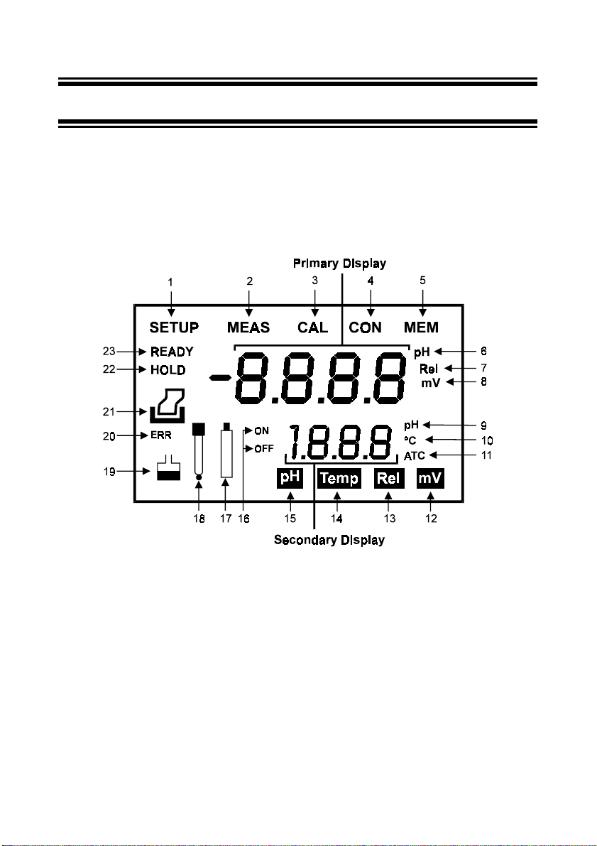
2.1 Display
The LCD has a primary and secondary display.
•
The primary display shows the measured pH or ORP values.
•
The secondary display shows the measured temperature.
The display also shows error messages, keypad functions and program functions.
1
. SETup mode indicator
2
. MEASurement mode indicator
3
. CALibration indicator
4
. CONfirm indicator
5
. MEMory recall mode indicator
For pH 100 only
(
6
. pH indicator
7
. Relative mV indicator (
100 only
8
. mV indicator
)
)
For pH
Figure 1: Full LCD Screen
9
. pH buffer selection indicator
10
. Temperature indicator
11
. Automatic Temperature
Compensation indicator
12
. mV measurement mode
indicator
13
. Rel mV measurement mode
14
. Temperature measurement
15
. pH measurement mode
For pH 100 only
indicator (
mode indicator
indicator
2
16
. ON & OFF indicator
17
. Low battery indicator
18
. Probe indicator
19
. Buffer indicator
20
)
. ERRor indicator
21
. Printer indicator (
only
)
22
. HOLD indicator
23
. READY indicator
For pH 100
Page 7

2.2 Keypad
A large membrane keypad with tactile feedback makes the instrument easy to use. Each
button, when pressed, has a corresponding graphic indicator on the LCD (Figure 1). Some
buttons have several functions depending on its mode of operation.
Key Function
ON/OFF
HOLD
MODE
CAL/MEAS
CON
!!!!
""""
/
MI / MR (
in pH 100
Powers on and shuts off the meter. The meter will start in pH measurement mode.
Freezes the measured reading. To activate, press HOLD while in measurement
mode. To release, press HOLD again.
Selects the measurement parameter. Default is pH measurement. Press MODE to
toggle between pH, Temperature, Rel mV (
measurement mode.
Toggles between Calibration and Measurement mode.
1. If you are in pH measurement mode, press CAL/MEAS to enter pH calibration
mode.
2. If you are in temperature measurement mode, press CAL/MEAS to enter
temperature calibration mode.
3. If you are in Rel mV (
enter Rel mV measurement calibration mode.
While in SETup (
the measurement mode.
CONfirm function:
selections in SETup mode.
In Calibration mode:
1. If you are in pH calibration mode, press
buffer calibration values.
2. If you are in temperature calibration mode, press
temperature values in °C.
3. If you are in Rel mV (
adjust mV values.
In SETUP mode (
!!!!
Press
only
In measurement mode (pH, Rel mV or mV) press MI (memory input) to store values
)
with its corresponding temperature values in the memory. Press MR (memory recall)
to retrieve data from memory.
Allows you to print current measurement to either the printer or the computer.
only in pH 100
""""
or
key to scroll through options in each SETup programs.
only in pH 100
) menu, pressing CAL/MEAS takes you out and into
Press to confirm values in Calibration mode and to confirm
only in pH 100
only in pH 100
only pH 100
) measurement mode, press CAL/MEAS to
) calibration mode, press
):
), mV, & back to pH
!!!!
""""
or
key scrolls up or down the
!!!!
""""
or
key to adjust
!!!!
""""
or
key to
only in pH
(
100
SETUP (
in pH 100
)
only
Takes you into the SETUP mode. This mode lets you customize meter preference
)
and defaults, view calibration, electrode offset data, clear memory, change pH
resolution, and communication protocol setting.
3
Page 8
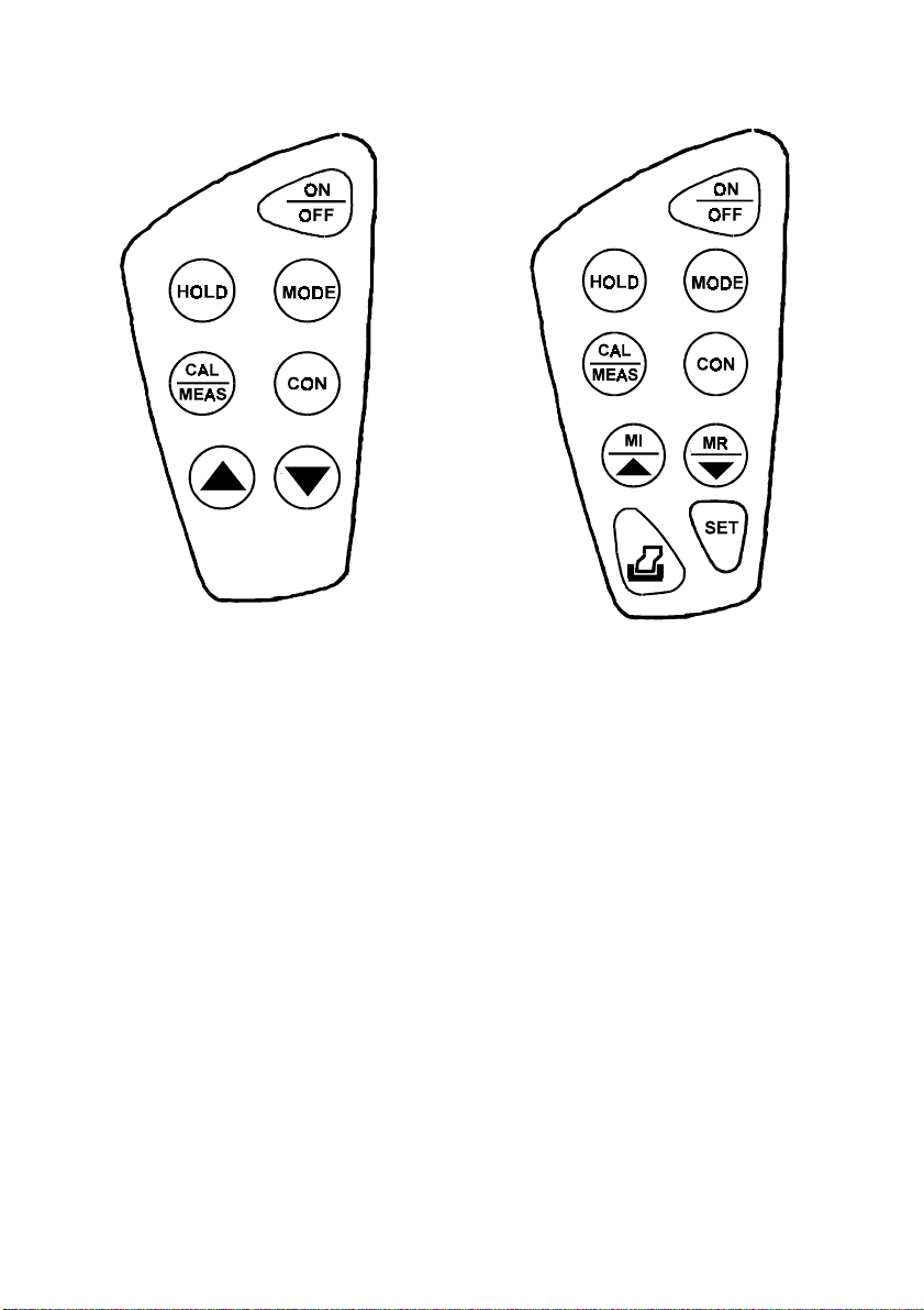
Figure 2: Keypad of pH 10 meter
Figure 3: Keypad of pH 100 meter
4
Page 9
3 PREPARATION
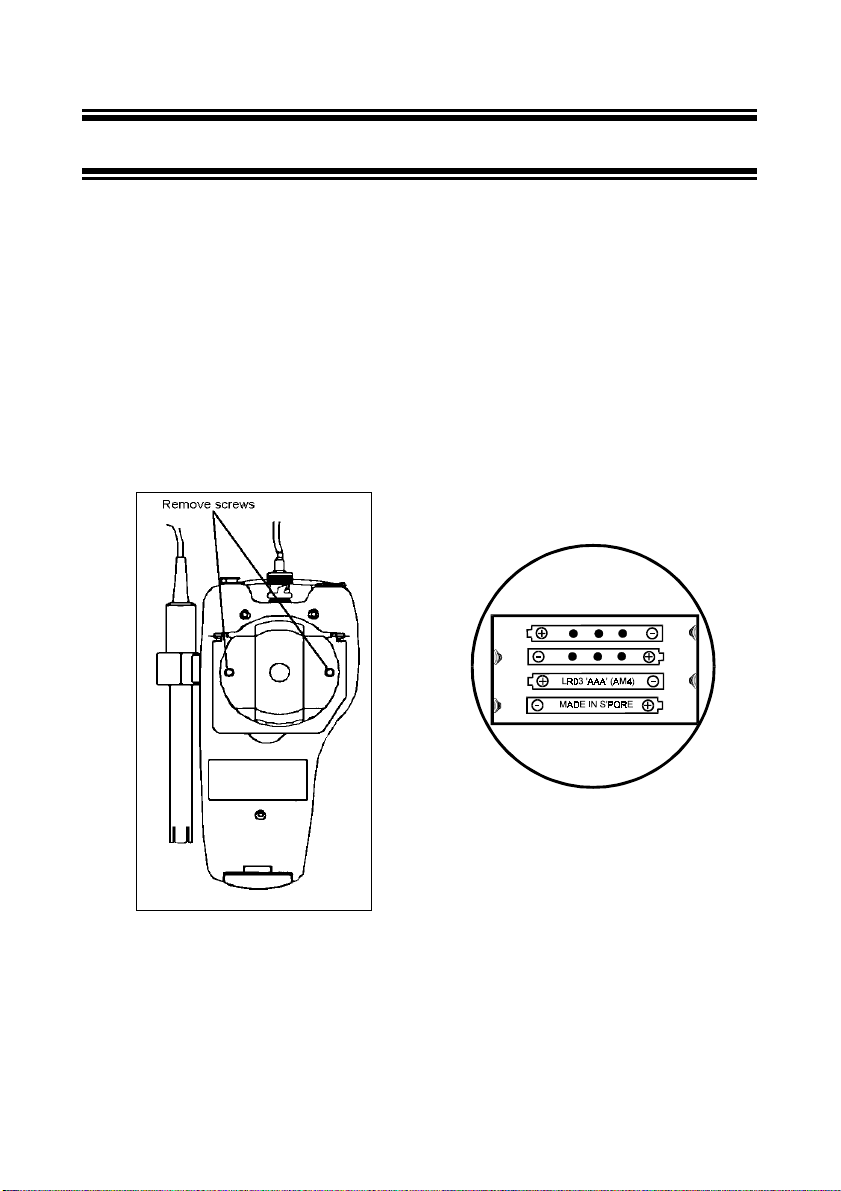
3.1 Inserting the Batteries
The CyberScan is packaged with 4 “AAA” alkaline batteries required for operation. To insert
the batteries into the CyberScan, follow the procedure outlined below.
1. Use a Phillips Head screwdriver, remove the two screws (Figure 4) with the hinge closed.
2. Remove the battery cover. Note the polarity and insert the batteries into the battery
compartment correctly (Figure 5).
3. Replace the battery cover into its position and screw back using the two screws removed
earlier.
Your CyberScan hand-held meter is now ready for operation.
Figure 4: Take out battery cover by
removing 2 screws
Figure 5: Battery position
5
Page 10
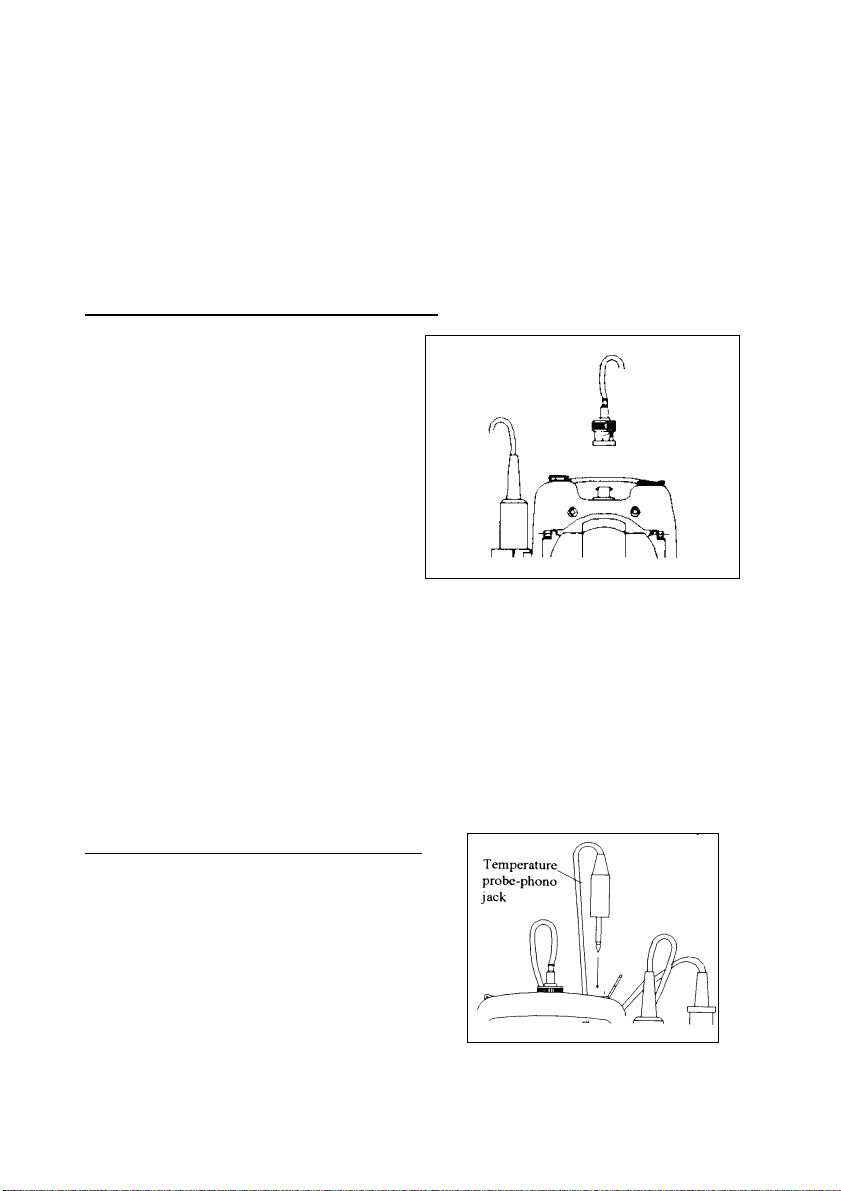
3.2 Connecting the pH Electrode, Temperature Probe & Electrode Holder
The Eutech Instruments CyberScan pH 10/100 meter uses any standard pH, ORP, or Ion
Selective Electrode (ISE) with a BNC connector. For Automatic Temperature Compensation
(ATC), this meter requires a temperature probe with a phono-jack connector.
NOTE: It is important that water does not get onto the BNC connector. Also avoid touching the
connector with soiled hands.
3.2.1 To connect pH, ORP or ISE electrode
1. Slide the electrode connector of the
electrode over the BNC connector
socket on the meter.
2. Make sure the slots of the connector are
in line with the posts of the socket.
3. Slide the BNC connector of the probe
over (Figure 6).
4. Rotate and push connector clockwise
until it locks.
5. To remove electrode, push and rotate
the connector anti-clockwise.
6. While holding onto the metal part of
the connector, pull it away from the meter.
7. Be careful not to use excessive force.
CAUTION:
Do not pull on the probe cord or the probe wires might disconnect.
Figure 6: Connect pH or ORP electrode using BNC
Refer to “Accessories” section for information on temperature probe and other electrodes.
3.2.2 To connect the temperature probe:
The temperature probe (provided) uses a phono
jack to connect with the socket on the CyberScan.
Insert the jack fully into the socket (Figure 7).
Figure 7: Connecting the temperature
6
probe
Page 11
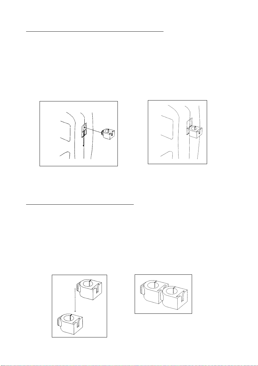
3.2.3 Attaching the electrode onto the electrode Holder
The CyberScan pH meter is packed with two electrode holders (provided). They are designed
for easy use and installation. Care must be taken to avoid use of excessive force in the
process of attaching these components.
1. Locate the slot on the right-hand side of the meter.
2. Gently slide the flange of the holder into the slot on the meter. Make sure the holder is
secured properly into the slot (Figure 8).
3. You can attach the electrode holder in different positions (Figure 10).
Figure 8: Slide in the electrode holder
3.2.4 To attach a second electrode holder:
The electrode holder is designed such that you can attach one holder onto another. Up to two
electrodes (using the BNC connector and phono-jack) can be used with the CyberScan meter
at any one time.
1. Align the flange of the second electrode holder with the slot of the first holder (Figure 9).
2. Slide the flange of the second holder into the slot of the first holder until the tops of the
holders are aligned and secure.
Figure 9: Connecting 2 electrode
holders together
7
Page 12
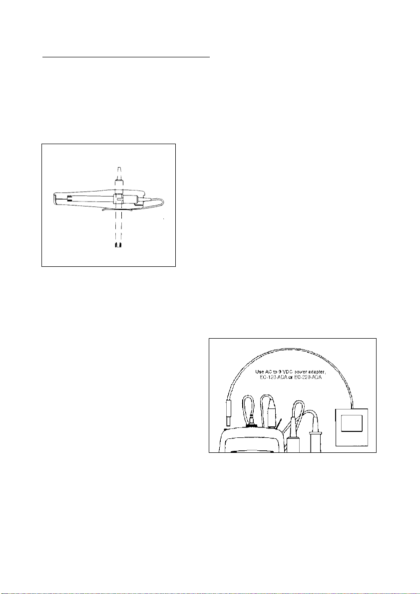
3.2.5 Insert the electrode into the holder
1. Do not use excessive force when inserting electrodes into the holders.
2. Insert the pH electrode into the opening of the first holder until the top housing of the
electrode touches the top of the holder.
3. If you are using a separate temperature probe, insert the probe into the opening of the
second holder until the ridge on the housing touches the top of the holder.
NOTE: The holder is designed for probes 12 mm in
diameter. Electrodes larger than 12 mm may not fit in
the holder. Forcing the electrode into the opening
may damage the holder or your electrode.
The electrode holders can be attached in different
positions for greater flexibility in measurement and
storage purposes.
Simply slide out the electrode
holders and reoriented into appropriate
Figure 10: Different positions using
electrode holder
orientation before putting into position.
3.3 Connecting the AC/DC Adapter
Besides using four AAA-sized batteries as
power source, the CyberScan pH 10/100
meter can also operate from the power
mains using an AC/DC power adapter either
at 120/220 VAC (sold separately). This is
extremely useful if you have an A.C. power
source available (e.g. laboratory).
Before plugging in, switch off the meter and
the power source of adapter. This is a safety
precaution that should be adhered to
safeguard your CyberScan meter.
1. Switch off the meter and power sources.
2. Select the correct voltage of AC/DC Adapter. See Figure 11.
NOTE: Output Voltage: 12 V D.C.; Current: 500 mA. Ensure that the input mains
voltage (120/240 VAC) matches your adapter requirements.
3. Insert the D.C. jack into the socket and switch on the power to the adapter, followed by
the CyberScan meter.
Figure 11: Putting the AC Power Adapter
8
Page 13
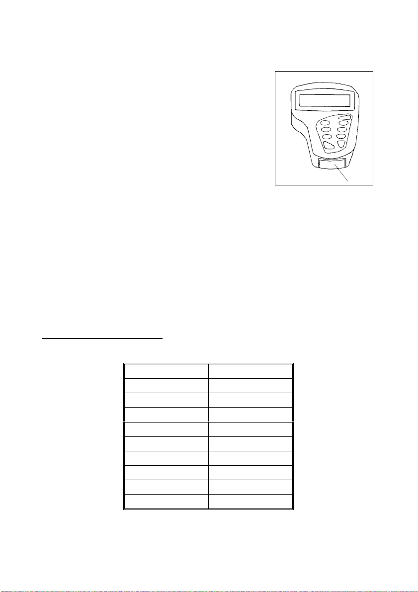
3.4 Connecting the RS232C Cable (Only For CyberScan pH 100)
The CyberScan pH 100 meter provides a RS232C output for
you to transmit your readings either to a printer or a computer
via a cable. This is useful in instances where the CyberScan
meter is used for continuous monitoring of a certain process or
experiment. Data output to the printer or the computer can then
be evaluated.
The data is output in the ASCII format. This format allows the
data to be imported by a wide variety of software that read
ASCII data (e.g. Microsoft’s Excel, Lotus, Quattro-pro etc.).
Eutech Instruments provides a complimentary Data Acquisition
Software (DAS) that captures data transmitted into an ASCII
file for later use.
1. Open the printer port cover located at the bottom end of
the meter. Do not use excessive force when doing this.
See Figure 12.
2. Noting the orientation of the RS232C connector, plug the male connector into the
RS232C port of the CyberScan.
3. Fasten the RS232C connector by fastening the two screws at the side of the male
RS232C connector.
3.4.1 RS232C Configuration
Figure 12: Location of
RS232C Port (Only in pH
100)
The CyberScan pH 100 meter has a 9 pin female RS232C connector with the following pinout:
PIN NO. DESCRIPTION
12 Transmit Data
34 DSR (Data Set Ready)
5GND
67 CTS (Clear to Send)
89-
A one-to-one connection can be made with a 9 pin RS232C port of the computer.
9
Page 14

Figure 13: Pin number position of the 9-pin RS 232C port
In case CyberScan pH 100 meter’s output has to be sent to a 25 pin RS232C connector, t he
following cable configuration may be used:
CyberScan pH 100 25 pin connector
2 (TxD) (RxD) 3
4 (DSR) (DTR) 20
5 (GND) (GND) 7
7 (CTS) (RTS) 4
1. CyberScan pH 100 uses hardware handshake i.e. CyberScan pH 100 expects both DS R
and CTS lines to be active before it sends data.
2. If the [PRINT] key is pressed while the printer is not ready or if the printer is off, the
CyberScan pH 100 meter displays error message by showing both the printer and th e
ERR annunciators blinking alternately, and awaits the printer to be ready (Figure 14).
3. While the meter is displaying printer error, you
may press CAL/MEAS key to return to the
measurement mode.
Figure 14: Error in printing
10
Page 15

4 CALIBRATION
4.1 Preparing the Meter for Calibration
Before starting calibration, make sure you are in the correct measurement mode. When you
switch on the meter, the meter starts up in the pH measurement mode.
Before calibrating, select the correct mode by pressing the MODE key. There are 4 modes:
[pH] for pH measurements,
[Temp] for Temperature measurements,
[Rel] [mV] for Relative mV measurements
[mV] for millivolt measurements.
Be sure to remove the protective electrode storage bottle or rubber cap of the electrode before
calibration or measurement. If the electrode has been stored dry, wet the electrode in tap
water for 10 minutes before calibrating or taking readings to saturate the pH electrode surface
and minimize drift.
Wash your electrode in deionized water after use, and store in electrode storage solution. If
storage solution is not available, use pH 4.01 or 7.00 buffer solution.
Do not reuse buffer solutions after calibration. Contaminants in the solution can affect the
calibration, and eventually the accuracy of the measurements. Refer to Accessories for
information on Eutech Instruments pH buffer solutions.
It is recommended that you perform at least a 2-Point Calibration using standard buffers that
adequately cover the expected measurement range prior to measurement. 1-Point Calibration
can also be used for quick measurements. Make sure that the calibration point is close to the
sample value to be measured.
The CyberScan pH 10 & pH 100 meters are capable of multi-point calibration to ensure
enhanced accuracy throughout the pH measurement range. The number of pH calibrations
points and pH buffer standards used are:
(only for pH 100 meter)
Meter Number of Calibration Points Buffer Points (USA standard)
pH 10 Up to 3 points pH 4.01, 7.00 & 10.01
pH 100 Up to 5 points pH 1.68, 4.01, 7.00, 10.01 & 12.45
11
Page 16
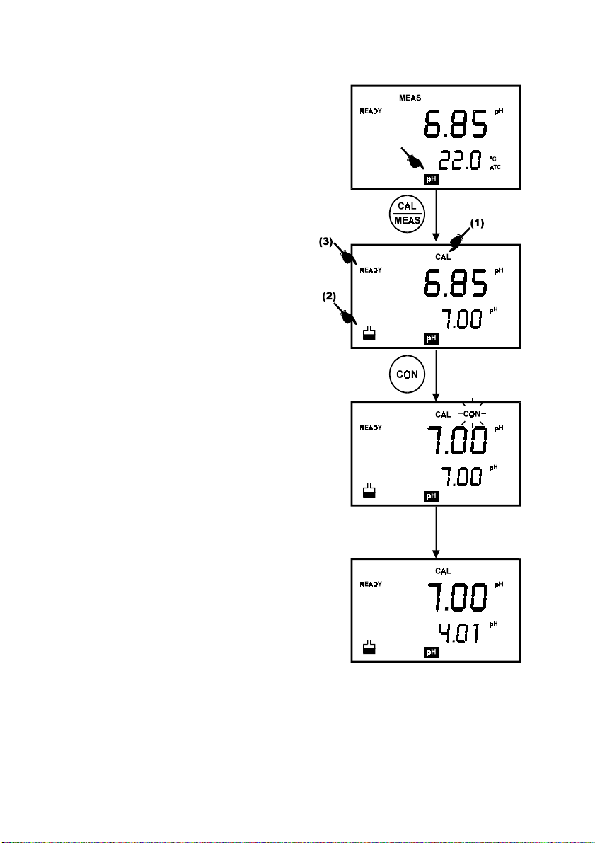
4.2 pH Calibration with ATC
To activate the Automatic Temperature
Compensation (ATC), simply plug in the
temperature probe into the phono jack. The ATC
indicator will be displayed on the LCD (Figure
15). If the ATC indicator is not displayed, it
indicates that the temperature probe is either not
properly connected to the instrument or is faulty.
1. Switching ‘ON’ the meter by pressing the
ON/OFF key.
2. All the LCD segments will be displayed
momentarily for a few seconds to check
that all segments are in working condition.
Then, the LCD will switch to the [pH]
measurement mode.
3. Select the [pH] mode using the MODE key.
(See Figure 15 on right).
4. Rinse the electrode well with deionized
water or rinse solution. (Do not wipe the
electrode with tissue paper as this may
cause a build-up of electrostatic charge on
the glass surface!).
5. Dip the probe into the calibration buffer.
The end of the probe must be completely
immersed into the sample. Stir the probe
gently to create a homogeneous sample.
6. Press the CAL key to calibrate the meter.
7. The display will show the [CAL] mode and
the buffer icon as shown (see [1] & [2] in
Figure 15).
8. The primary display will show the
measured reading while the secondary
display will indicate that pH 7.00 is ready for
calibration.
9. Wait for the measured pH value to stabilize.
The READY annunciator will light up. See [3]
in Figure 15.
Figure 15: pH Calibration at pH 7.00
12
Page 17
NOTE: In pH 100 meter, you can program the meter to turn off the ‘READY’
indicator through the SETup mode.
10. Press the CON key to confirm the calibration. The ‘CON‘ indicator flashes for one second
and disappears.
11. Upon confirmation, the instrument is calibrated to the buffer indicated in the secondary
display.
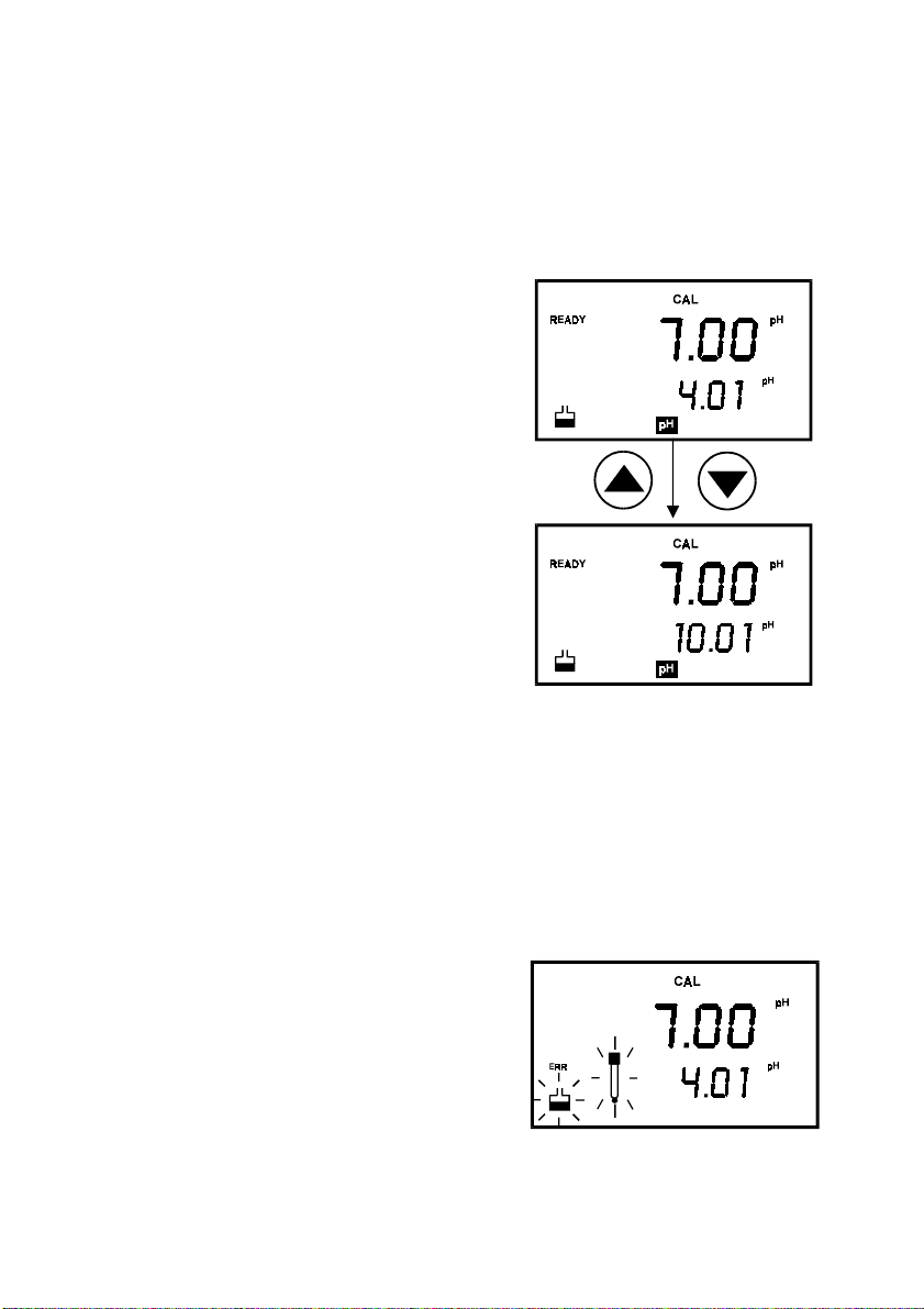
12. The secondary display automatically scrolls to
the next pH buffer calibration option i.e. pH
10.01.
13. For 1-Point Calibration, this can be ignored and
you can exit to the [MEAS] mode by selecting
the CAL/MEAS key.
NOTE: The ‘Or’ indicator flashes if the selected
buffer value is not within +/- 0.50 pH
from the measured pH value.
14. To calibrate 2 or more points, press the Ml/
!
and MR/" key to scroll through the various
buffer pH options.
15. Select the second pH buffer for calibration
accordingly. Repeat steps 4 to 14 above.
16. Once calibration is confirmed at the second point,
Figure 16: Calibration for second point
you can proceed to calibrate at the third point
without the need to return to Measurement mode.
Just select the desired buffer by using Ml/! or
MR/" key.
NOTE: For pH 100 meter you can check on which buffer calibration points were being
calibrated using Program 2.2 under SETUP mode (see section 9.2.1 on Electrode Data).
NOTE: To exit from pH calibration mode without confirming calibration, DO NOT press
CON in step 11. Press CAL/MEAS instead.
If the selected buffer value is not within ±1.0 pH from
the measured pH value: the electrode and buffer icon
blink and the ERR annunciator appears in the lower
left corner of the display.
Figure 17: Err message and electrode
icon will appear if incorrect buffer are
13
used
Page 18

4.3 pH Calibration (without ATC)
When the CyberScan meter is not used with a temperature probe, it is necessary to calibrate
the temperature first prior to pH calibration.
1. Calibrate for temperature as described in the procedure in Section 4.4.1 -
Calibration Without ATC Probe
2. Next, proceed with the pH calibration as described in the above section.
3. The meter is now calibrated at a fixed temperature.
NOTE: To exit this program without confirming the temperature calibration value, DO NOT
press CON. Press CAL/MEAS instead.
.
Temperature
14
Page 19
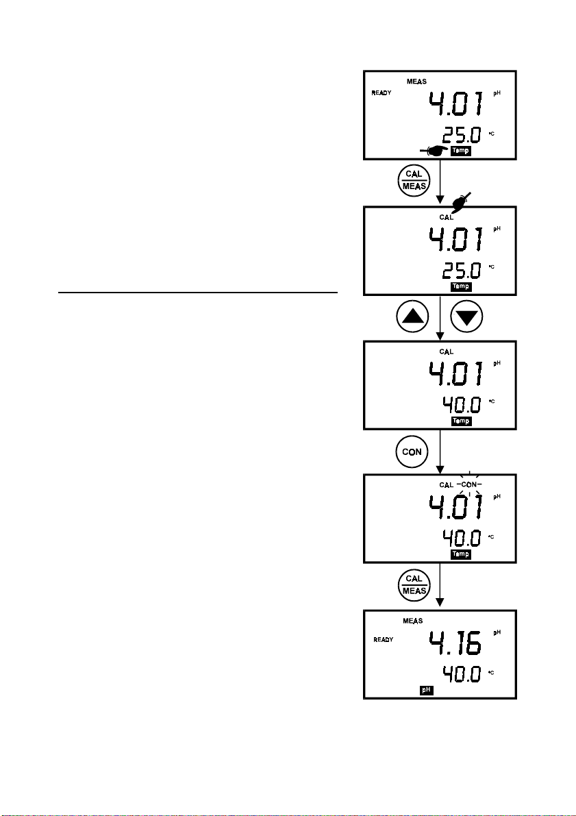
4.4 Temperature Calibration
The temperature sensor is factory calibrated. Calibrate the
temperature probe only if you suspect the temperature
errors that may have occurred over a long period of time or
if you have a replacement temperature probe. This
procedure offers offset adjustment of probe to ensure more
accurate temperature measurement.
In the event where there is no temperature sensor, this
procedure can also be performed for Manual Temperature
Compensation (MTC).
4.4.1 Temperature Calibration Without ATC Probe
1. Switch the meter on. Press the MODE key to select
temperature mode, [Temp].
2. Press the CAL/MEAS key to enter temperature
calibration mode. The primary display indicates the pH
value, and the secondary display shows the
temperature.
3. Press ! or " key to select temperature value that
matches the temperature reading shown in your
reference thermometer.
4. Once you have selected the correct temperature,
press CON key to confirm.
5. The CON indicator flashes for one second and
disappears.
6. Press CAL/MEAS key to return to the pH
measurement mode.
NOTE: To exit this program without confirming the
temperature calibration value, DO NOT press CON. Press
CAL/MEAS instead.
Figure 18: Temperature
Calibration
15
Page 20
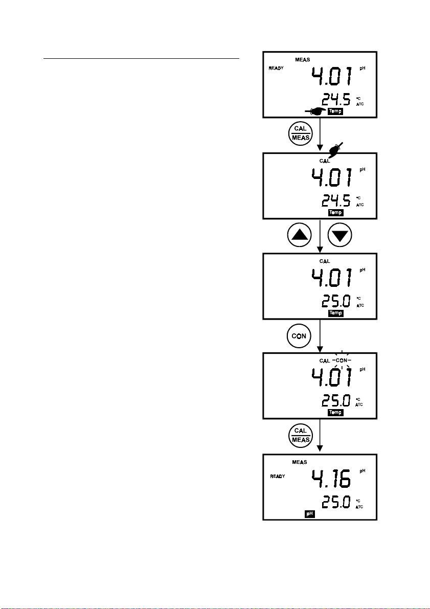
4.4.2 Temperature Calibration With ATC Probe
1. Make sure the ATC probe is attached to the meter.
Refer to Figure 7 in Section 3.2.2.
2. Switch the meter on. Note the ATC indicator.
3. Press the MODE key to select tempera ture mode,
[Temp].
4. Dip the ATC probe into a solution of known
temperature (i.e. a temperature bath). Allow time for
the temperature probe to stabilize.
5. Press the CAL/MEAS key to enter temperature
calibration mode. The primary display indicates the
pH value, and the secondary display shows the
temperature.
6. Press ! or " key to select temperature.
7. Once you have selected the correct temperature,
press CON key to confirm.
8. The CON indicator flashes for one second and
disappears.
9. Press CAL/MEAS key to return to the pH
measurement mode.
NOTE: To exit this program without confirming the
temperature calibration value, DO NOT press CON.
Press CAL/MEAS instead.
Figure 19: Temperature calibration
with temperature probe
16
Page 21
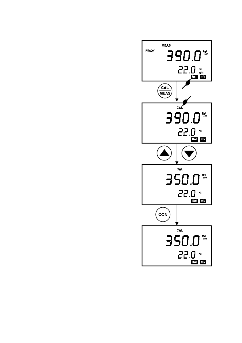
4.5 Calibration Procedure for Relative mV Measurements (For pH 100 Only)
Relative millivolt calibration is used in ISE
measurements, where it is common to use the lowest
concentration mV value as the base value for
measurements. All subsequent measurements will
then be based on this reference value. For Relative
mV calibration, carry out the following procedure:
1. Press the MODE key to enter the Relative mV
mode.
2. The primary display shows the absolute mV
reading while secondary display shows the
temperature.
3. On pressing the CAL key, the calibration mode is
activated. The ‘CAL’ indicator is displayed on the
LCD. The rest of the display remains the same.
4. With the Ml/! and MR/" keys, adjust the
displayed absolute mV value to the base value
required e.g. 350.0 mV (Figure 20).
NOTE: To exit this mode or re-enter the desired value
without confirming, DO NOT press CON key.
Press the CAL/MEAS key instead.
5. Press CON key to confirm the calibration. The
CON indicator flashes for one second and
disappears.
6. The LCD now displays 0 mV reading. The meter
is now calibrated for Relative mV measurements.
7. On pressing the CAL/MEAS key, the meter
returns to the measurement mode. The primary
display now indicates the Relative mV readings,
bearing in mind that the selected base value is
350.0 mV.
The value displayed is calculated as follows:
Displayed Value = (Absolute mV reading) – (Relative
mV Base Value)
Figure 20: Relative mV calibration (For
pH 100 only)
NOTE: For pH 100 model, you can check the Relative mV base value in the SETUP program
P2.4.
17
Page 22

4.6 Erasing Calibrated Values (For pH 100 only)
To erase the calibrated values in the memory follow either one of the following procedures:
1. Enter the SETUP mode. (See section 9.1). Program 1.0 clears all memory in storage,
including the calibrated values. You cannot selectively delete data.
2. Or you can recalibrate the instrument. A new calibration value automatically overwrites
the existing value in the memory.
18
Page 23

5 MEASUREMENT
This meter is capable of taking measurements with automatic or manual temperature
compensation. Automatic temperature compensation only occurs when a temperature sensor
is plugged into the meter. If there is no temperature sensor plugged into the meter, the default
manual temperature setting is automatically 25.0 °C. You can manually set the temperature to
match your working conditions using a separate thermometer.
NOTE: Remove the protective rubber cap or soaker bottle of the electrode before proceeding
with measurement. Take care not to exert too much force as this may cause damage to the
electrode.
5.1 Automatic Temperature Compensation
For automatic temperature compensation
(ATC) simply plug the temperature probe
into the meter. The ATC indicator will light
up on the LCD.
NOTE: If you are using a temperature
probe, the probe must be submersed in the
liquid you are measuring.
Figure 21: ATC annunciator will light up when
connected to temperature probe
19
Page 24

5.2 Manual Temperature Compensation
IMPORTANT
: For manual compensation, you must
disconnect the temperature probe. The [ATC] annunciator
will disappear from the LCD.
1. Switch the meter on. Press the MODE key to select
[TEMP] mode.
2. Press the CAL/MEAS key to enter Temperature
calibration mode. The CAL indicator will appear above
the primary display.
3. The prima ry display shows the current pH reading and
the secondary display shows the default temperature
value 25 ºC.
4. Check the temperature of your sample using an
accurate thermometer.
5. Press the " or ! keys to set the temperature to the
measured value obtained from step 4.
6. Press CON to confirm the selected temperature. The
[CON] indicator will flash momentarily.
7. Press the CAL/MEAS key to exit and return to pH
measurement mode.
The meter will now compensate pH readings for the
manually set temperature.
NOTE: To exit this program without confirming the manual
temperature compensation value, DO NOT press CON in
step 6. Press CAL/MEAS instead.
20
Figure 22: pH measurement using
Manual Temperature
Compensation
Page 25

5.3 Taking Measurements
Be sure to remove the electrode soaker bottle or
protective rubber cap on the electrode before
measurement.
To take readings:
1. Rinse the probe with de-ionized or distilled water
Figure 23: Measurement mode
before use to remove any impurities adhering to
the probe body. If the pH electrode has
dehydrated, soak it for 30 minutes in Eutech Instruments electrode storage solution or
2M – 4M KCl solution (sold separately).
2. Press ON to switch on meter. The MEAS annunciator appears on the top center of th e
LCD. The ATC indicator appears in the lower right-hand corner to indicator Automatic
Temperature Compensation (section 5.2 on Manual Temperature Compensation).
3. Dip the probe into the sample.
4. When dipping the probe into the sample, the sensor or the glass bulb of the electrode
must be completely immersed into the sample. Stir the probe gently in the sample to
create a homogeneous sample.
5. Allow time for the reading to stabilize. Note the reading on the display.
6. To toggle between pH and mV (or Rel mV) readings, press the MODE key.
The READY mode informs you that the readings are stable within a range of ±0.01 pH. When
this occurs, the mode annunciator READY appears on the top left corner of the display. The
reading is held until the measured value exceeds the specified range when the READY
display is turned off.
NOTE FOR pH 100 ONLY:
•
The READY mode is turned on by default i.e. when the SETUP (READY) mode is
not programmed. You can verify this by going through SETUP mode (See section
9.3.2). If READY mode is switched off, the annunciator will not be displayed.
•
For ATC measurements, attach the probe to the CyberScan. The ATC mode
annunciator lights up. Insert the probe into the solution to be measured so that the
sample temperature can be recorded and compensated for.
21
Page 26

6 HOLD FUNCTION
This feature allows you to hold the value of the
measurement reading until it is more convenient to
note the reading. This mode can be invoked at any
time when you are in the MEAS mode. You may
also store the held value into memory using MI/
available only in pH 100 meter
key (
).
1. In the measurement mode (either pH, mV or
Rel mV, press the HOLD key.
2. “HOLD” indicator will appear on the display.
3. To release the held value, press HOLD again.
You can continue to take measurements.
NOTE:
•
The meter shuts off automatically after 20 minutes after last key is pressed. If the
meter is shut off either automatically or manually, the HOLD value will be lost.
!
Figure 24: HOLD function
•
In the pH 100 model, the SETUP function allows you to turn off the auto shut-off
feature.
22
Page 27

7 MEMORY FUNCTION (FOR pH 100 ONLY)
The memory function is available only in the CyberScan pH 100 meter. This meter stores data
in sets:
•
pH and temperature
•
mV and temperature
•
Relative mV and temperature
The pH 100 meter can store up to 16 sets of data in any combination of values. For example,
you can store 7 pH and 9 mV values.
This meter uses the Last-In-First-Out (LIFO) method of memory management. If the memory
is already full, the first value that was stored in the memory will be erased to create space for
the new value to be input.
7.1 Memory Input
To store a reading:
1. During any measurement function [MEAS], press
MI key to input any data into the memory.
2. The [MEM] annunciator will flash momentarily
(Figure 25).
3. The meter then returns to measurement mode.
4. You can switch to the next measurement mode (by
pressing the MODE key), and press MI key to input
data into memory.
NOTE: If the memory is full, the first value stored will be
erased to create space for the new value.
Figure 25: Memory In function
23
Page 28

7.2 Memory Recall
This function recalls the previous readings stored in the memory. You can only access MR
from the measurement mode.
Make sure you are in the correct measurement mode to retrieve previously stored data. For
example, if you want to retrieve data stored during pH measurement mode, you will need to be
in pH measurement mode to retrieve the data.
To recall readings:
1. Switch the meter ON, and press MODE key for
the appropriate measurement parameter.
2. Press the MR key once to retrieve the last reading
stored.
3. The memory annunciator, [MEM], will appear on
the display (See Figure 26).
4. Note the reading.
5. If necessary, press MR key again to retrieve the
next memory.
6. To retrieve data from another measure ment mode
(for example, mV), press MODE key until you
arrive at pH measurement mode.
7. Press the MR key once to retrieve the last reading
stored in pH. Note the reading.
Figure 26: Memory Recall function
8. If necessary, press MR key again to retrieve the next memory.
9. Once all readings are recorded, press CAL/MEAS key to exit memory recall mode and
return to measurement mode.
NOTE: Memory data is retained even if the power of the unit is switched off. The memory will
be completely erased according to the following situation:
a. When the batteries are removed (all functions, including memory, are reset);
b. Memory can be cleared through SETUP function under program P1.0.
c. When meter is reset through SETUP function under program P1.1.
24
Page 29

8 PRINT FUNCTION (FOR pH 100 ONLY)
The CyberScan pH 100 is equipped with a PRINT key that facilitates the printing of data from
a printer or storage of data into the computer in the form of a data file.
8.1 Using the CyberScan pH 100 With The Printer
1. To use the CyberScan pH 100 directly with a printer, the printer should have either a 9
pin or a 25 pin RS 232C serial port.
2. Printer dip switches should match with the CyberScan meter communication setup. The
printer should have options to receive 8 data bits, even (2), odd (1) or none (0) parity bit
and one (1) or two (2) stop bits. These parameters are standard printer options. Please
refer to your printer’s instruction manual for more information on its communication setup
protocol.
3. Use the cable provided to connect the meter to the printer. If the printer has a 25 pin
connector, use a 9 to 25 pin converter (available separately) or make your own cable
taking note of the connection parameters as described in Section 3.4.1 on page 9.
4. Set the dip switches of the printer to accept serial data. This would be required if the
printer has both serial and parallel interfaces. Set the dip switches to accept 8 data bits
(Normally, printers would have a selection for 7 or 8 data bits).
5. Turn on the meter.
6. Set the printer dip switches or change the CyberScan pH 100 setup parameters for the
proper baud rate, parity and stop bits. Refer to Section 9.4 for more detail.
7. Ensure that these parameters are identically set on both the printer and the meter.
8. Insert the paper and switch the printer on.
9. To send data to the printer, press the PRINT key.
Printing Errors
Problem Probable Cause
Prints Garbage Baud rate/parity/data bits mismatch
Nothing is printed Cable not properly connected or improper printer dip switch
setting.
The CyberScan meter displays error by blinking the printer and error annunciators alternatel y
if the printer is not ready to receive data or if the printer is off. See Figure 14 on Page 10. As
soon as the printer is ready, the error display will automatically go off. While the meter is
displaying the printer error, you may press the ‘CAL/MEAS‘ key to go back to the
measurement mode.
25
Page 30

8.2 Sending Data To Computer
To send data to the computer, connect the RS232C cable from the base of the CyberScan pH
100 to the communication port of the computer. Load and run the CYDATA data acquisition
program ensuring that the parameters of the settings in the CyberScan pH 100 and the
CYDATA are identical (See Section 10.4 “
the PRINT key.
8.2.1 Printing Measurement Data
To print any data that currently being measured, press the PRINT key as shown in the
diagram below. Note that the PRINT capability is available for the [MEAS], [Rel mV] and [mV]
modes. The data will be printed onto the printer paper or the screen of the CYDATA program
automatically.
8.2.2 Printing Data From Memory
The CyberScan pH 100 meter can print data that is stored in the memory. Firstly ensure that
the cables are properly connected to either the printer or the computer and the units are
configured to receive data from the meter.
Change the mode to the mode of measurement from which data needs to be printed. For
example, the data stored is in the memory location of the mV mode.
Scroll to the data that needs to be printed by pressing the MR/" key. To print, press the
[PRINT] key.
The data displayed will then be sent to the printer or the computer.
Parameter Format
pH, Rel mV, mV -
Temperature -
Date mm/dd/yy
Time hh/mm/ss
Setting Up CYDATA
” on page 37). To print, press
Note:
Abbreviation
mm month
dd date
yy year
hh hour
mm minute
26
Page 31

The data will be printed in the following format:
pH : 5.41 Temp: 25.0 Date: 12-21-1996 Time: 09:52:39
pH : 5.43 Temp: 25.0 Date: 12-21-1996 Time: 09:52:42
pH : 5.74 Temp: 25.0 Date: 12-21-1996 Time: 09:53:57
pH : 6.03 Temp: 25.0 Date: 12-21-1996 Time: 09:54:00
R.mv: 1.4 Temp: 25.0 Date: 12-21-1996 Time: 09:57:00
R.mv: -1.1 Temp: 25.0 Date: 12-21-1996 Time: 09:57:03
R.mv: -3.2 Temp: 25.0 Date: 12-21-1996 Time: 09:57:07
R.mv: -4.9 Temp: 25.0 Date: 12-21-1996 Time: 09:57:10
mv : -6.9 Temp: 25.0 Date: 12-21-1996 Time: 09:57:15
mv : -8.2 Temp: 25.0 Date: 12-21-1996 Time: 09:57:18
mv : -10.3 Temp: 25.0 Date: 12-21-1996 Time: 09:57:22
mv : -11..2 Temp: 25.0 Date: 12-21-1996 Time: 09:57:24
mv : -12.9 Temp: 25.0 Date: 12-21-1996 Time: 09:57:28
mv : -14.1 Temp: 25.0 Date: 12-21-1996 Time: 09:57:31
mv : -15.9 Temp: 25.0 Date: 12-21-1996 Time: 09:57:37
mv : -17.4 Temp: 25.0 Date: 12-21-1996 Time: 09:57:40
mv : -17.8 Temp: 25.0 Date: 12-21-1996 Time: 09:57:43
mv : -18.6 Temp: 25.0 Date: 12-21-1996 Time: 09:57:46
mv : -19.7 Temp: 25.0 Date: 12-21-1996 Time: 09:57:49
mv : -22.5 Temp: 25.0 Date: 12-21-1996 Time: 09:57:52
mv : -20.9 Temp: 25.0 Date: 12-21-1996 Time: 09:57:55
mv : -33.0 Temp: 25.0 Date: 12-21-1996 Time: 09:57:58
pH : 5.69 Temp: 25.0 Date: 12-21-1996 Time: 10:11:35
pH : 5.45 Temp: 25.0 Date: 12-21-1996 Time: 10:11:38
27
Page 32

9 ADVANCED SETUP FUNCTIONS (FOR pH 100 ONLY)
The advanced setup mode lets you customized your meter’s preferences and defaults. The
Eutech Instruments’ standard CyberScan meter features four different programs that organize
all setup parameters. Each has been divided into several options. The programs and options
are elaborated under the following sections:
Program Descri ption Sub-Group Functions Section
P 1.0 Software Initialization Memory Clear and Reset Options 9.1
P 2.0 View Electrode Data pH slope & offset, calibration data, & relative
P 3.0 Meter Configuration Set pH resolution, READY setting, & auto-off
P 4.0 Communication Data
Setting
mV offset
function
Set baud rate, parity & stop bit. 9.4
To enter the SETUP mode, press the SET key from either the pH, Relative mV or mV
measurement [MEAS] mode. The meter automatically enters Program 1, Option 0 (P1.0).
NOTE: Entry to SETUP is only accessible from the [MEAS] mode.
Selection of the CON key confirms selection of the options chosen. The instrument then
automatically scrolls to the next program. Within each program, the user can use MI/! or
MR/" keys to make appropriate selections. There are some options that only permit the
viewing of data and are useful for diagnostic purposes.
Ensure that the CON key is pressed to confirm your option in each program. Should you
desire to exit from the program after the confirmation of your choice or abort the [SETUP]
mode, press the CAL/MEAS key to return to the [MEAS] mode.
Addendum 1 shows the overall program setup and the factory default settings.
9.2
9.3
28
Page 33

9.1 Program 1 – Software Initialization
This program deals with the initialization of the memory
and calibration data. “OFF” is the default setting for both
Memory Clear and Reset. Accidental selection of wrong
option will wipe out the memory.
9.1.1 P1.0 : Memory Clear
Activation of this option by selecting ‘ON‘ clears all stored
measurement values in the memory (5 sets of values each
for pH, mV and Rel. mV with temperature). Under default
condition this option is not activated (set to OFF).
9.1.2 P1.1 : Reset
Activation of this option by selecting ‘ON‘, resets the
instrument. The instrument immediately switches off. You
need to power ‘ON‘ the instrument before proceeding with
any other functions.
RESET clears all data in memory (5 sets of values each for
pH; mV and Rel. mV with temperature), calibration data and
setup data. All settings return to factory defaults. The
RESET is OFF by default.
This feature is useful when the meter is used by someone
who needs to recalibrate to a different electrode and select
his own SETUP options.
Press CON key to continue to next program. NOTE: Data
cannot be selectively deleted.
Figure 27: P1.0, Memory Clear
Figure 28: Reset Meter
29
Page 34

9.2 Program 2 – Electrode Data
This program allows you to check on electrode
parameters for diagnostic purposes.
9.2.1 P2.0 : Electrode Offset
The primary display shows the pH electrode offset value
in mV. The offset is calculated based on the buffer 7.00
calibration. If no calibrations have been performed, the
primary display shows -0.00 mV.
9.2.2 P2.1 : Electrode Slope
The primary display indicates the electrode slope in
percentage. The slope displayed is the average slope
based on the calibrations performed. If the meter has not
been calibrated, or under default conditions the primary
display reads 100.00.
9.2.3 P2.2: Calibration pH buffer data
Records all the pH buffer calibrations made on the meter.
This option allows you to view all 5 calibration points.
Use MI/! or MR/" key to scroll through the five
calibration points. See Figure 29.
If there has been no calibration performed at any
particular buffer option, the display will indicate “- - - -“.
See Figure 30.
Figure 29: Electrode diagnostics,
offset & slope
Figure 30: No calibration performed
Figure 29: View calibration points
30
Page 35

9.2.4 P2.3: Calibration Temperature
Indicates the temperature of the last calibration
performed. This is a View Only mode.
Default setting is 25 degrees C.
See Figure 31.
9.2.5 P2.4: Relative mV offset value
The primary display indicates the Relative mV base
value in mV. This base value is based on your preselected value during calibration for REL mV
measurement. If REL mV has not been calibrated or
under default conditions, the primary display reads 0
mV.
Figure 31: Temperature of the last
calibration performed
Figure 32: Relative mV base value
31
Page 36

9.3 Program 3 –Meter Configuration
The following three options are available to the user for
customization:
9.3.1 P3.0 : Resolution
The resolution of the instrument in the pH measurement
mode can be user selected to 0.1 or 0.01 pH. Under
default condition, the instrument is set for 0.01 pH
resolution.
LCD Value Description
0.01 A resolution of 0.01 pH is shown.
0.1 A resolution of 0.1 pH is shown.
1. Use MI/! or MR/" keys to select the resolution
desired. See Figure 33.
2. Press CON key to continue to P3.1.
9.3.2 P3.1 : Ready selection
Activation of the READY option ensures that the READY
indicator is displayed when the electrode reading has
stabilized.
The stabilization tolerances for the various measurement
ranges are as indicated below. Under default conditions,
i.e. when the [SETUP] mode is not programmed, the
instrument has this option activated.
MODE VARIATION RANGE
pH ± 0.01 pH
mV ± 0.8 pH < 400 mV
mV ± 1.2 mV > 400 mV
ON READY Indicator will appear
when the reading stabilizes
within ± 0.01 pH
OFF READY indicator will not appear.
Figure 33: Setting pH resolution
Figure 34: READY Selection
32
Page 37

9.3.3 P3.2 : Auto-Off
Activation of the AUTO-OFF option automatically powers
off the instrument 20 minutes after the last key selection.
This feature is useful for conserving battery power.
Under default condition, the instrument has this option
activated.
•
ON - Meter will automatically switch off 20
minutes after the last key operation.
•
OFF - Auto Off mode is switched off.
Figure 35: Select Auto-off feature
33
Page 38

9.4 Program 4 – Communication Setup
This program allows you to set up the instrument’s
communication parameters of the CyberScan 100 to
enable proper communication with the printer or
computer of choice.
9.4.1 P4.0: Baud Rate
You can select a baud rate either at 2.4, 4.8, 9.6 or 19.2
Kbps. Under default conditions, the baud rate is set to 9.6
Kbps.
1. From pH or mV measurement mode, press SETUP
key.
2. Press CON key (10 times) until P4.0.
3. Use MI/! or MR/" key to change different baud
rate.
4. Press CON ke y to confirm and continue to set Parity
in P4.1.
See Figure 36.
NOTE:
To exit without confirming baud rate value, press
CAL/MEAS key. This will bring you back to the
measurement mode.
Figure 36: P4.0 Setting Baud
34
Rate
Page 39

9.4.2 P4.1 : Parity
Parity check allows the unit to monitor the integrity of
the data that it transmits. To accommodate for the
variances in standards used, three different parity
checks have been provided in the table below. The
default parity is even (2).
Value Parity
0No Parity
1 Odd Parity
2 Even Parity (Default)
9.4.3 P4.2 : Stop Bit
The Stop Bit allows the selection of the appropriate
stop bit when transmitting to other peripheral devices
(such as printers). You can select the Stop Bit to be 1
or 2 depending upon the model and make of peripheral
device (The instruction manual of peripheral device
should indicate the stop bit used). Under default
conditions the stop bit is 1 (one).
Figure 38: P4.2 Setting Stop Bit
value
Figure 37: P4.1 Setting Parity Value
35
Page 40

10 CYBERCOMM PORTABLE - DATA ACQUISITION SOFTWARE
(DAS FOR pH 100 ONLY)
The CyberComm Portable software is designed for Eutech’s CyberScan pH 100 and CON 200
meters to allow you a convenient means of capturing data for future analysis using other
software program such as LOTUS 123, EXCEL or DBASE in Windows
cumbersome to record and transfer data from one media to another before the required
processing can be done. With the CyberComm Portable, this redundant processing can be
eliminated or reduced.
10.1 System Requirements
To run the CyberComm Portable program, the following is required:
1. PC - IBM Compatible XT and above with CD-ROM Drive
2. EGA Monitor and above
3. Windows
©
Operating System ‘95 and above
4. Connecting communication RS232C cable
10.2 Loading CyberComm Portable
©
. Often one finds it
Figure 39 - Insert Eutech Instruments' CD-ROM containing Data Acquisition Software (DAS) into your CD-ROM
drive and click on START button and RUN command.
36
Page 41

Figure 40 - Click on 'Browse' button and locate CD-ROM drive
Figure 41 - Locate the CyberComm Portable Setup program in the CD-ROM under "CyberComm Portable" sub-
directory.
37
Page 42

Figure 42 - Select "Setup" program and click the OPEN button.
Figure 43 - InstallShield Wizard dialog box appears.
Figure 44 - Click on Next button.
38
Page 43

Figure 45 - Key in your name and company name and click NEXT button.
Figure 46 - To select another Destination Directory to install the program, click on BROWSE button. Otherwise, click
NEXT button.
39
Page 44

Figure 47 - Creating a new program folder. Click on NEXT button.
Figure 48 - Click on NEXT button.
40
Page 45

Figure 49 - The CyberComm Portable DAS program is fully installed. Click on FINISH button to end installation.
41
Page 46

10.3 Running CyberComm Portable
Before running the CyberComm Portable program, please ensure that the RS232 cable is
connected between the computer’s serial port and the meter’s port.
A 1-meter RS232 cable, 9-pin male to 9-pin female connector (order no. EC-CA01M09F09) is
supplied with the CyberScan pH 100 meter.
For additional information on the connection, please refer to section 3.4 “Connecting the
RS232C Cable (Only For CyberScan pH 100)”.
Figure 50 - Run the CyberComm Software program
42
Page 47

BUTTONS & CHECK-BOX
Figure 51 - The opening screen will appear as above.
•
Enable Connection
- Click this button to enable communication between meter and
computer.
•
•
•
Clear Readings
Save Readings
Time Stamp
- To include Time and Date stamp when collecting the data. Time and
- To clear all data and start all over again.
- To save all data displayed in either *.dat or *.txt format.
date information comes from the computer.
43
Page 48

Figure 52 - Under File Menu setting, you can change various parameters. Under ABOUT menu, details of Eutech
Instruments' contact information, email address and updates are shown.
MENU
•
Communication Settings
- To set communication port number, baud rate speed,
parity and stop bits protocol.
•
•
•
•
Open
- To open previously saved data file.
Save
- To save current data captured.
Save As
Exit
- To save current data set in another format such as *.dat or *.txt.
- To exit from CyberComm Data Acquisition Software program.
44
Page 49

Figure 53 - Communication Settings for computer's Com port. It must
pH 100 meter. Please refer to Section 3.4.1 “RS232C Configuration” for the settings.
COMMUNICATION SETTINGS
•
Connecting Use
•
Baud Rate
- To select communication port, 1 or 2.
- To select different baud rate, 2400, 4800, 9600 or 19200 bps (bits per
second).
•
Parity
•
- To select different parity, Even, Odd or None.
Stop Bits
- To select different stop bits, 1 or 2.
match
with COM port settings on CyberScan
Figure 54 - Under SAVE AS menu, you can save your data as *.dat or *.txt formats
45
Page 50

10.4 Capturing And Printing Data Into Computer Using CyberComm
Portable
After matching the Communication Settings between your computer using CyberComm
Portable and the CyberScan pH 100 meter, you can now capture data into your computer for
analysis and storage purposes.
1. Ensure the 1-meter RS232 communication cable (supplied with the meter) is connected
between the computer and the CyberScan pH 100 meter’s Com port. Refer t o section 3.4
“Connecting the RS232C Cable (Only For CyberScan pH 100)” for connection procedure.
2. Switch on the CyberScan pH 100 meter and run the CyberComm Portable DAS software
as indicated in Figures 50 and 51.
3. Click “ENABLE CONNECTION” button.
4. With the CyberScan pH 100 meter switched on, press the PRINT key to send data to the
computer. See Figure 55 below.
5. You can use MODE key on the meter and change to other parameter such as mV or Rel
mV and print data accordingly.
6. You can also check off the Time Stamp function, so as to print without the Time and Date
information.
7. You can click Clear Readings button to begin another set of measurements, or click Save
Readings to store readings for future retrieval.
Figure 55 - A set of data print in CyberComm Portable DAS
46
Page 51

10.5 Trouble-shooting Guide
a) Problem: Unable to PRINT
When press PRINT key on CyberScan pH 100 meter, the “Print” and “Err” annu nciators
blink on the meter’s LCD screen as shown in Figure 56.
Figure 56 - "Print" and "Err" icons blinking
POSSIBLE CAUSES SOLUTIONS
You have not "ENABLE CONNECTION" in the
CyberComm Portable DAS program.
The "Communication Settings" in the CyberComm
Portable DAS program is different from meter's setup.
The COM port number in the CyberComm Portable
DAS program is wrong.
Your computer's COM port setting may be wrong. Check your computer's hardware settings (through
You may have used the wrong communication cable. Make sure you use the RS232C cable supplied
Click on "ENABLE CONNECTION" in the CyberComm
Portable DAS program.
Match the COM port number, baud rate, parity and
stop bits information between the CyberComm
Portable DAS program and the meter.
Change the COM port number (1 or 2) in the
CyberComm Portable DAS program.
Windows OS, BIOS, or any other OS) and refer to
computer's manual or consult with the computer's
manufacturer.
together with the meter (Part No. EC-CA01M09F09).
Check the RS232C configuration as described in the
meter's instruction manual.
b) Problem: Unusual characters appear in data
When press PRINT key on CyberScan pH 100 meter, additional characters such as the
following appear.
06/18/2001 1:48:38 PM? R.mv? -900? Temp: ?22.6
POSSIBLE CAUSES SOLUTIONS
The Baud rate, parity or stop bit information are not
matched.
Check the communication setup for both CyberComm
Portable DAS program and meter and ensure both are
the same.
To report any bugs, please e-mail to techsupport@eutechinst.com
47
Page 52

11 ELECTRODE CARE
11.1 Electrode Maintenance
pH electrodes are susceptible to dirt and contamination and need to be cleaned regularly
depending on the extent and condition of use.
11.1.1 Storage
The best results, always keep the pH bulb wet, preferably in pH 4 buffer with 1/100 part of
saturated KCl. Other pH buffers or tap water are also acceptable storage media, but avoid
storage in de-ionized water. The protective rubber cap filled with the buffer solution provides
ideal storage for long periods.
11.1.2 After Use
After measurement is complete, follow the sequence elaborated below for storage.
1. Wash the electrode and reference junction in deionized water.
2. Close the refilling hole by returning its rubber sleeve or stopper cap (Necessary for only
refillable electrodes).
3. Store the electrode as mentioned above (Storage section 11.1.1).
11.1.3 Electrolyte Replacement (for refillable electrodes only)
The reference electrolyte needs to be refilled when the electrode has been used for an
extended period, or when the internal electrolyte has dried up. To accomplish this, follow the
procedure detailed below.
a) Remove the protective rubber cap or sleeve
Remove the protective rubber sleeve to expose the filling port of the electrode. Remove the
old reference electrolyte with a syringe and a flexible tube.
b) Fill the new reference electrolyte
Add in fresh electrolyte until it reaches the level of refilling port. The reference electrolyte used
should be 4M KCl. Replace the rubber sleeve.
c) Re-use the electrode
Rinse the liquid junction with deionized water and tap dry.
NOTE: If these steps fail to restore normal electrode response, you may attempt to rejuvenate
it. (See section 11.4 on Rejuvenation Procedure).
48
Page 53

11.2 Electrode Cleaning
Electrodes that are mechanically intact can be restored to normal performance by one or
combination of the following procedures.
a) Salt deposits:
Dissolve the deposit by immersing the electrode in tap water for ten to fifteen minutes. Then
thoroughly rinse with deionized water.
b) Oil / Grease Films:
Wash electrode pH bulb in a little detergent and water. Rinse electrode tip with deionized
water.
c) Clogged Reference Junction:
Heat a dilute KCl solution to 60-80 °C. Place the sensing portion of the pH electrode into the
heated KCl solution for approximately 10 minutes. Allow the electrode to cool while immersed
in some unheated KCl solution.
d) Protein Deposits:
Prepare a 1% pepsin solution in 0.1M HCl. Allow the electrode to stand in this solution for five
to ten minutes. Rinse the electrode with deionized water.
11.3 Electrode Activation
Generally, if the procedure of storage and maintenance had been closely followed, the
electrode can be used immediately. However, should the electrode response become
sluggish, it may be possible that the bulb has dehydrated. The bulb can be re-hydrated by
immersing the electrode in an ideal storage solution (e.g. buffer pH 4 solution) for 1- 2 hours. If
this fails, the electrode may require re-activation.
At no time should one touch or rub the glass bulb as this causes the build-up of electrostatic
charge.
If the above procedure does not re-activate the electrode to acceptable status, try rejuvenating
the electrode by following the procedure outlined below.
11.4 Rejuvenation Procedure
a) Dip and stir the electrode in freon or alcohol for 5 minutes.
b) Leave the electrode in tap water for 15 minutes.
c) Dip and stir the electrode in concentrated acid (e.g. HCl, H
d) Repeat Step b.
e) Dip and stir in strong base (NaOH) for 5 minutes.
f) Leave for 15 minutes in tap water.
49
) for 5 minutes.
2SO4
Page 54

g) Test with standard calibration buffer solutions.
CAUTION:
Proper eyewear and gloves must be worn when preparing these chemicals and
performing this operation.
Finally, test with standard calibration buffer solutions to see if the electrode yields acceptable
results. You may repeat steps ‘c’ to ‘f’ again for better response (maximum 3 times). If the
response does not improve, then the electrode has completed its useful life. Replace with a
new electrode.
50
Page 55

12 ERROR MESSAGES
The following table provides a guideline to enable diagnosis of possible problems indicated by
the messages generated by the CyberScan meter. The table also provides possible solutions
to the problems encountered.
ERROR MESSAGE INDICATES POSSIBLE CAUSE CORRECTIVE
Err. 1 (in primary
display)
Err. 2 (in primary
display)
Err. 3 (in primary
display)
Err. 4 (in primary
display)
Err. Annunciator Wrong keypad input Wrong input in selected
Electrode icon & buffer
icon blinks & Err
annunciator lights up
Battery icon lights up Low Battery Battery power is low Replace batteries with
Memory write error Instrument too old (> 10
Memory checksum error Hardware failure. Turn OFF meter and
ADC error Hardware error. Turn OFF meter and
Keypad error One or more keys on the
Calibration Incorrect buffer used or
years) or hardware
failure.
keypad are stuck.
mode.
contaminated buffer
solution
ACTION
Turn OFF meter and
turn it ON. Return to
dealer if necessary.
turn it ON. Return to
dealer if necessary.
turn it ON. Return to
dealer if necessary.
Turn OFF meter and
turn it ON. Return to
dealer if necessary.
Release key. Select
valid operations
depending on mode.
Check if the right buffer
was selected or use
fresh buffer solution.
fresh ones as soon as
possible.
51
Page 56

13 TROUBLE-SHOOTING
PROBLEM PROBABLY CAUSE REMEDIAL ACTION
Nothing is displayed when the
ON/OFF key is selected.
1. Batteries not in place.
2. Batteries (+ & - poles) not in
correct polarity.
3. Weak batteries.
1. Insert batteries.
2. Re-insert batteries in the
correct polarity.
3. Replace batteries or attach
AC adapter.
Unstable reading 1. Insufficient reference
Slow responses. 1. Dirty electrode. 1. Clean electrode. Rejuvenate
Meter is not responding to key
press.
electrolyte in electrode.
2. Broken electrode.
3. External “noises” or induction
(e.g. electrical ‘noise’ caused
by a nearby motor).
4. Dirty electrode.
1. HOLD mode in operation.
2. Broken electrode.
3. Internal program error.
1. Fill electrode with reference
electrolyte.
2. Replace electrode.
3. Remove or switch off
interfering device.
4. Clean the electrode.
Rejuvenate if necessary.
if necessary.
1. Cancel HOLD mode.
2. Replace electrode.
3. Reset all internal programs
by re-inserting battery.
52
Page 57

14 INFORMATION ON pH MEASUREMENT & ELECTRODE
The previous sections of this manual describe the various features of the instrument and
practical aspects of its operation. This section provides a general description of pH
measurement principles. It also provides tabulations of pH buffer changes with temperature.
Lastly, it includes a list of available accessories.
14.1 pH Measurements
14.1.1 Liquid Junction Potential
The liquid - junction potential is the difference in potential created at the liquid - liquid phase
boundary at the electrode tip, due to dissimilar composition of the test solution and the
saturated KCl electrolyte. The sign and size of the liquid - junction potential depends upon the
composition of the two solutions, the temperature and the geometry of the type of junction
used.
When two solutions of different compositions come into contact, ion diffusion occurs at the
point of contact.
When there is a high liquid junction potential, measured values differ greatly from the true
value.
14.1.2 Asymmetry Potential
Within the glass electrode is an internal electrode that contains a reference solution of pH 7.
When the electrode is placed in a pH 7 solution, the pH values within and outside the
electrode are the same, and no potential ought to be produced. In practice, however, an
electric potential called asymmetry potential, is generated.
It has been shown that asymmetry potential varies with the pH of the solution in contact with
the glass, with age, with temperature, with the shape of the membrane, with the thickness of
the membrane, with impurities in the reference solution, and any imperfections in the glass.
In addition, when the glass membrane dries out, the asymmetry potential increases and leads
to measurement errors. That is why it is important to keep the glass hydrated prior to use, by
soaking the electrode in a buffered solution or tap water. (Do not use de-ionized water). The
purpose of soaking the glass electrode is to obtain a swollen low resistance glass surface and
to stabilize the asymmetry potential of the electrode. This swollen surface is generally spoiled
by drying, prolonged immersion in dehydrating solutions or chemical attack, such as etching
by alkalis or hydrofluoric acid. Hence, it is necessary to work with a well-soaked glass
electrode to ensure a constant asymmetry potential.
53
Page 58

14.1.3 pH and Temperature
The electromotive force generated in the glass electrode varies with the temperature of the
solution. As a result the response of the pH electrode is subjected to variations in temperature.
Automatic Temperature Compensation compensates for this variance.
The temperature dependable of solutions vary considerably. Some may show an increase in
pH while others a decrease for the same temperature variation. This is why when you are
measuring pH values at a particular temperature, even with a pH meter having ATC, you must
record the solution’s temperature along with the pH value, or the measurement may be
meaningless.
Temperature variation also cause variation in liquid junction potential, asymmetry potential,
and the pH value of the reference solution. To reduce these factors, it is important to ensure
that the temperature of the standard calibrating solution and the sample solution are the same.
14.2 Use of Standard pH Buffers
Standard pH buffer solutions are used to calibrate or standardize a pH meter before you
measure the pH of a sample. They serve as reference standards for the basis of comparison
between measurements.
The more common standard buffers are the pH 4.01, pH 7.00 and pH 10.01. The others
include pH 1.68 and pH 12.45.
For 1-point calibration, you only need a general pH value. Use a standard buffer of pH 7.00 or
a standard buffer whose pH value is close to that of the sample.
2-point calibration is used when you know that the sample is acidic or basic.
•
For acidic sample: use standard buffers of pH 7.00 and pH 4.01
•
For basic sample: use standard buffers of pH 7.00 and pH 10.01
3-point calibration is necessary when the sample’s pH is completely unknown. All pH 7.00, pH
4.01 and pH 10.01 standard buffers should be used.
54
Page 59

14.3 Standard pH Buffers
The following table shows the various pH values at different temperature of the solution during
calibration.
Temperature
(ºC)
0 1.67 4.01 7.12 10.32 13.43
5 1.67 4.01 7.09 10.25 13.21
10 1.67 4.00 7.06 10.18 13.00
15 1.67 4.00 7.04 10.12 12.81
20 1.68 4.00 7.02 10.06 12.63
25 1.68 4.01 7.00 10.01 12.45
30 1.69 4.01 6.99 9.97 12.29
35 1.69 4.02 6.98 9.93 12.13
40 1.70 4.03 6.97 9.89 11.99
45 1.70 4.04 6.97 9.86 11.84
50 1.71 4.06 6.97 9.83 11.70
55 - 4.08 6.97 9.81 60 - 4.10 6.98 9.79 70 - 4.12 6.99 9.76 80 - 4.16 7.00 9.74 90 - 4.20 7.02 9.73 -
pH 1.68
(oxalate)
pH 4.01
(phthalate)
pH 7.00
(neutral
Phosphate)
pH 10.01
(carbonate)
pH 12.45
(Saturated
Calcium
Hydroxide
Solution)
55
Page 60

15 LIST OF ACCESSORIES
15.1 Replacement Meter and Meter acces sories
Ordering Code No. Item
EC-PH10/01N Basic CyberScan pH 10 hand-held meter (pH/mV/ºC) complete with 1 pc of
EC-PH100/01N Deluxe CyberScan pH 10 hand-held meter (pH/Rel mV/mV/ºC/R232C) with
EC-PH-TEM01P Temperature probe for CyberScan pH 10 and pH 100 meters.
15X000700 Electrode holder for CyberScan hand-held meters.
EC-FE72521-01B
EC-FE72522-01B
EC-FE73528-01B “3-in-1” pH/Temperature (ATC) combination epoxy-body electrode, 12x110 mm, 1-m
EC-CA01M09F09 CyberScan to PC communication cable – 9-pin male to 9-pin female connector, 1-m
EC-DA-2000
EC-PH-CYBERKIT
EC-POUCH-02 Carrying pouch for CyberScan hand-held meter.
EC-120-ADA 120 VAC power adapter (120 VAC/9 VDC, 50/60 Hz), 2-pin type
EC-220-ADA 220 VAC power adapter (220 VAC/9 VDC, 50/60 Hz), 2-pin type
For a list of other pH, ORP and ISE electrodes, refer to Section 15.3 and 15.4 for more information.
temperature probe (EC-pH-TEM01P) and 2 pcs of electrode holders (15X000700)
communication interface. Complete with 1 pc of temperature probe (EC-pH-TEM01P),
2 pcs of electrode holders (15X000700), 1 pc of communication cable (ECCA01M09F09) and 1 pc Data Acquisition Software in CD-ROM (EC-DA-2000).
General purpose epoxy-body pH combination electrode,
mm, 1-m cable length.
General purpose epoxy-body pH combination electrode,
mm, 1-m cable length.
cable length.
cable length.
DAS (Windows
& DAS for Bench meters.
pH kit for pH 10 & pH 100 meter – Plastic carrying case comprises of 1 pc deionized
water bottle (480 ml, empty), 1 x pH 4.01, pH 7.00 & pH 10.01 buffer sachets (20-ml),
4 pcs calibration jars (30-ml, empty), & 1 pc rinse/waste water bottle (480-ml, empty).
©
version – CyberComm Portable) for CyberScan pH 100 & CON 200
single-junction
double-junction
, 12x110
, 12x110
56
Page 61

15.2 Calibration Solutions
Ordering Code No. Item
EC-BU-4BX pH 4.01 buffer tablets (box of 100 tablets, 10 strips X 10 tablets)
EC-BU-7BX pH 7.00 buffer tablets (box of 100 tablets, 10 strips X 10 tablets)
EC-BU-10BX pH 10.01 buffer tablets (box of 100 tablets, 10 strips X 10 tablets)
EC-BU-1BT pH 1.68 buffer solution, 480 ml bottle
EC-BU-4BT pH 4.01 buffer solution, 480 ml bottle
EC-BU-7BT pH 7.00 buffer solution, 480 ml bottle
EC-BU-10BT pH 10.01 buffer solution, 480 ml bottle
EC-BU-12BT pH 12.45 buffer solution, 480 ml bottle
EC-BU-4BS pH 4.01 buffer sachets, 20 ml x 20 pcs.
EC-BU-7BS pH 7.00 buffer sachets, 20 ml x 20 pcs.
EC-BU-10BS pH 10.01 buffer sachets, 20 ml x 20 pcs.
EC-RIN-WT pH De-ionized water rinse sachets, 20 ml x 20 pcs
EC-AST-PK pH sachet assortment pack – 5 each of pH 4.01, pH 7.00, pH 10.01 and de-ionized
EC-DPC-BT Protein cleaning solution for pH electrode
EC-RE-005 Storage solution for pH electrode
EC-ORP-PRE Pre-treatment solution for ORP measurement (475 mV), 480-ml bottle
EC-ORP-QUIN Quinhydrone 255 (255 mV, ± 15 mV @ 25 ºC) for ORP measurement
EC-ORP-QUIN086 Quinhydrone 86 (86 mV) for ORP measurement
Note: pH buffer solutions (480-ml bottle) have ±0.01 pH accuracy at 25 °C.
Sachets are individually sealed, single use pouch containing 20 ml of fresh, contamination free calibration
solution. pH buffer sachets have ±0.01 pH accuracy at 25°C and conductivity sachets have ±1% accuracy at
25°C.
water sachets per box.
15.3 Ion Selective Electrodes (ISE)
Ask our distributors for more details regarding Ion Selective Electrodes. The table below lists
the range of electrodes available.
Ion Ion
Ammonia ( NH3) Lead (Pb+2)
Ammonium (NH
Bromide (Br-)
Cadmium (Cd+2) Nitrogen Oxide (NOX)
Calcium (Ca+2) Perchlorate (ClO
Carbon Dioxide (CO2)pH (H
Chloride (Cl-) Silver/Sulfide (Ag+/S-2)
Copper (Cu+2)Sodium (Na
Cyanide (CN-) Sulfur Dioxide (SO2)
Fluoride (F-) Surfactant (X+, X-)
Flouroborate (BF
+
) Lithium (Li+)
4
Nitrate (NO
+
-
) Thiocyanate (SCN-)
4
57
-
)
3
-
)
4
)
+
)
Page 62

15.4 pH & ORP Electrodes
There is a wide range of electrodes for the user’s applications. A sampling is shown below.
Note that although only one electrode for each application is shown, there are multiple
electrodes available and these electrodes are often multi-application adaptable.
APPLICATION ELECTRODE
General purpose, aqueous pH measurements. Quality control, general laboratory
and aquarium water.
Tris buffers, clinical and biological media containing proteins, creams, fats and
cosmetics.
Research measurements, fruit juices, beer, milk and yogurt. EC-FG73905
High viscosity measurements such as emulsions, suspensions, paints and
varnishes.
Non aqueous solutions EC-FG73701
Low temperature measurements EC-FG73504
Low ionic strength solutions EC-FG73905
High temperature measurements EC-FG73792
Surface measurements such as paper, skin textile, leather and agar plates EC-FG72520
Solid or semi-solid samples such as cheese, meats, fruits, bread, etc. EC-FG63511
Portable pH meters, school and field use EC-FE73526
Micro samples (semi-micro curettes and NMR tubes) EC-FG43901
Test tube measurements EC-FG63507
Reference contamination problems EC-FG73701
Measurements in long narrow vessels EC-FG63507
Swimming pool pH control under continuous flow conditions EC-FE73526
Isoelectric focusing gels and other surface measurements that require small
diameter flat tip
Photographic chemicals, high pH samples (12 to 14 pH ) EC-FG74519
ORP measurements for general purpose EC-FG79601
Swimming pool ORP measurements EC-FE79602
ORP measurements for cyanide use EC-FG78685
ORP measurements requiring double junction reference EC-FG79861
Hydrofluoric acid and abrasive solution measurements EC-FE77689
Potentiometric measurements of chlorides and other halides. Bio-technology,
steam sterilizeable.
EC-FG73504
EC-FG73905
EC-FG63506
EC-FG52910
EC-FG70601
58
Page 63

16 METER SPECIFICATIONS
SPECIFICATIONS pH 10 pH 100
pH Range
Resolution 0.01 pH 0.01/0.1 pH (Selectable)
Accuracy ± 0.01 pH ± 0.01/0.1 pH
Slope Range 80% to 120% 80% to 120%
Temperature Range
Resolution 0.1 ºC 0.1 ºC
Accuracy ± 0.5 ºC ± 0.5 ºC
Millivolt Range (400 mV)
Resolution 0.1 mV 0.1 mV
Accuracy ± 0.2 mV ± 0.2 mV
Millivolt Range (2000 mV)
Resolution 1 mV 1 mV
Accuracy ± 2 mV ± 2 mV
No. Of Calibration Points 1 to 3 points 1 to 5 points
No. Of pH Buffer Values 3 5
pH Buffer Options pH 4.01, 7.00, & 10.01 pH 1.68, 4.01, 7.00, 10.01, 12.45
Relative mV functions Yes
Relative mV offset display Yes
Slope Display Yes
Offset Display Yes
Memory 16 data sets
Outputs RS232C
Auto Shut-off Yes (20 minutes) Selectable
Averaging/Stability (READY) Yes Selectable
Display Dual LCD Dual LCD
Hold Function Yes Yes
ATC Function 0.0 to 100.0 C 0.0 to 100.0 C
Inputs BNC, Phono, Power jack BNC, Phono, Power jack
Power Requirements
Battery Life > 50 hours > 50 hours
Environmental Requirements 0 to 50 ºC 0 to 50 ºC
Operating Range 0 to 50 ºC 0 to 50 ºC
Dimensions; Weight
0.00 to 14.00 pH -2.00 to 16.00 pH
0.0 to 100.0 ºC 0.0 to 100.0 ºC
-400 to +400 mV -400 to +400 mV
-2000 to +2000 mV -1600 to +1600 mV
4 ‘AAA’ Batteries; AC/DC Adapter
9 V, 500 mA
Meter: 18 x 9 x 4 cm; 220 g
Boxed: 24 x 23 x 7 cm; 600 g
4 ‘AAA’ Batteries; AC/DC Adapter
9 V, 500 mA
59
Page 64

17 ADDENDUM 1: FACTORY DEFAULT SETTINGS (pH 100 ONLY)
PROGRAM FUNCTIO N ACTIVE KEYS OPTIONS DEFAULT
P 1.0 Memory Clear MI/!; MR/
P 1.1 Reset MI/!; MR/
P 2.0 Electrode Offset - Viewing Only 0.0 mV
P 2.1 Electrode Slope - Viewing Only 100.0
P 2.2 pH Calibration Buffer
Data Display
P 2.3 Last pH Calibration
Temperature
P 2.4 Relative mV Offset - Viewing Only 0.00 mV
P 3.0 Resolution - [pH] mode MI/!; MR/
P 3.1 READY Selection MI/!; MR/
P 3.2 Auto Shut-Off MI/!; MR/
P 4.0 Baud Rate MI/!; MR/
P 4.1 Parity MI/!; MR/
P 4.2 Stop Bit MI/!; MR/
MI/!; MR/
"
ON ; OFF OFF
"
ON ; OFF OFF
"
1.68; 4.01; 7.00;
10.01; 12.45 (Viewing
only)
- Viewing Only 25.0
"
0.1 ; 0.01 0.01
"
ON; OFF ON
"
ON; OFF ON
"
2.4; 4.8; 9.6; 19.2
(Kbps)
"
0,1,2 (none, odd,
even)
"
1,2 1
SETTING
“ ——” No
calibration
performed.
C
9.6 Kbps
2 (even)
NOTE: The CON key is always active. It is used to confirm all program functions selected.
60
Page 65

18 WARRANTY & RETURN OF ITEMS
Eutech Instruments warrants this meter to be free from significant deviations in material and
workmanship for a period of three years from date of purchase. Eutech Instruments warrants
this probe to be free from significant deviations in material and workmanship for a period of six
months from date of purchase. Each instrument will have a warranty card with a specific serial
number. The warranty card must be endorsed by the Authorized Distributor at the point of
sale.
If repair or adjustment is necessary and has not been the result of abuse or misuse within the
designated period, please return – freight pre-paid – and correction will be made without
charge. Eutech Instruments alone will determine if the product problem is due to deviations or
customer misuse.
Out of warranty products will be repaired on a charged basis.
Exclusions
The warranty on your instrument shall not apply to defects resulting from:
•
Improper or inadequate maintenance by customer
•
Unauthorized modification or misuse
•
Operation outside of the environment specifications of the products
Return of Items
Authorization must be obtained from our Customer Service Department or authorized
distributor before returning items for any reason. A “Return Goods Authorization” (RGA) form
is available through our authorized distributor. Please include data regarding the reason the
items are to be returned. For your protection, items must be carefully packed to prevent
damage in shipment and insured against possible damage or loss. Eutech Instruments will
not be responsible for damage resulting from careless or insufficient packing. A restocking
charge will be made on all unauthorized returns.
NOTE: Eutech Instruments Pte Ltd reserves the right to make improvements in design,
construction, and appearance of products without notice.
61
Page 66

NOTES:
Date Time Recorded Value Remarks
62
Page 67

For more information on Eutech Instruments products, contact your nearest Eutech Instruments
distributor or visit our website listed below:
Manufactured by:
Eutech Instruments Pte Ltd.
Blk 55, Ayer Rajah Crescent,
#04-14/24 Singapore 139949
Tel: (65) 6778 6876
Fax: (65) 6773 0863
E-mail: marketing@eutechinst.com
Web-site: http://www.eutechinst.com
Distributed by:
 Loading...