

Page 1
gyM
y..
.
Instruction Manual
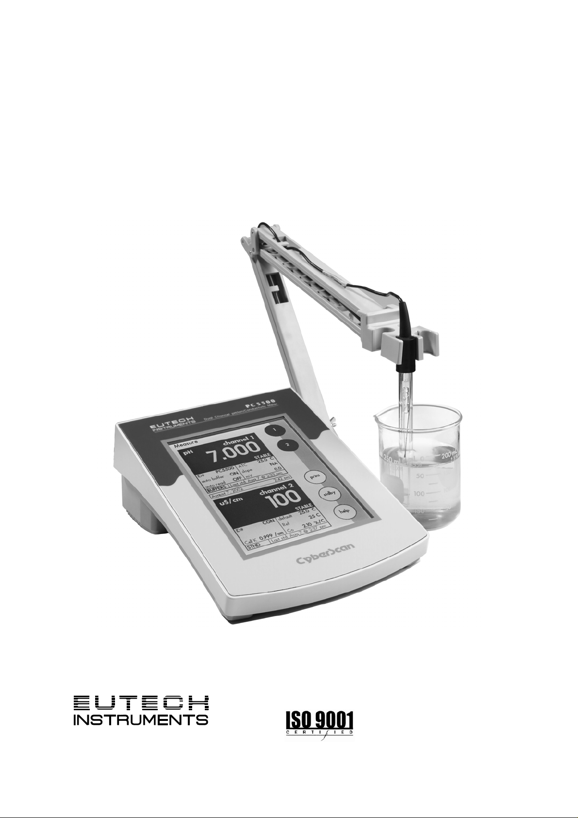
CyberScan PC 5500/ 5000
Bench pH, Ion & Conductivity Meter/ Bench pH & Conductivity Meter
(Also Applicable for CyberScan PCD 5500)
Technolo
adeEas
68X292329
Rev.1 08/03
Page 2

Page 3

PREFACE
Thank you for selecting a Eutech Instruments CyberScan Series
5000 bench meter. This meter measures pH, conductivity and ion
(PCD5500 & PC5500 only).
The instruction manual serves to explain the use of the CyberScan
Series 5000 bench meters as a step-by-step operational guide to
help you familiarize with the meter’s features and functions. It is
structured sequentially with illustration of diagrams that explains the
various functions and setup menus available.
This manual is written to cover as many anticipated applications and
uses of the CyberScan 5000 series bench meters as possible. If
there are doubts in the use of the meter, please do not hesitate to
contact the nearest Eutech Instruments’ Authorized Distributors or
call us at (65) 6778-6876 for Eutech Instruments’ Customer Service
Dept. for assistance.
Kindly remember to complete the warranty card and mail it back to
your Authorized Distributors or Eutech Instruments Pte Ltd.
Eutech Instruments reserve the rights to change, make improvement
and modify specifications without prior notice and cannot accept any
responsibility for damage or malfunction to the instrument caused by
improper use.
Copyright © 2002 Eutech Instruments Pte Ltd
All rights reserved. Rev.1 08/03.
Page 4

TABLE OF CONTENTS
1 INTRODUCTION 1
1.1 Introducing the CyberScan Series 1
2 UNPACKING THE METER 2
3 GETTING STARTED 3
3.1 Connectors (PCD 5500 only) 3
3.2 pH Electrodes & Ion Specific Electrodes (PCD5500 & PC5500 only 6
3.3 Conductivity Probes 8
4 USING THE METER 10
4.1 Touch screen Operation 11
4.2 Choosing a channel (for PCD5500 & PC5500 only) 12
4.3 Button Functions 14
5 SYSTEM SETUP 16
5.1 Access system setup 17
5.2 Select Language 19
5.3 Set Date 21
5.4 Set Time 23
5.5 Set Beeper Status 25
5.6 Select procedural level 27
5.7 Set Print Configuration 29
5.8 Set Baud Rate 31
5.9 Set Number of Bits 32
5.10 Set Stop Bits 33
5.11 Set Parity 34
5.12 Set Operator 35
5.13 Set Display Contrast 37
5.14 Display Meter Information 39
5.15 Reset to Factory Defaults 40
6 pH SETUP 41
6.1 Access pH setup 42
6.2 Set Sample ID# 44
6.3 Select Buffer Group 48
6.4 Set pH Custom Buffer Group 50
6.5 Select Buffer Recognition 52
6.6 Select Auto Read Mode 53
6.7 Set pH Stability Criteria 54
6.8 Set Default Temperature 56
6.9 Set Isopotential Point 58
6.10 Set Alarm Limits 60
6.11 Set Print Criteria 62
6.12 Set Print Interval 64
6.13 Set Data Storage Criteria 66
6.14 Set Display Resolution 68
6.15 Set Display Configuration 70
6.16 View Stored Data 72
7 mV SETUP 76
7.1 Access mV Setup 77
7.2 Set Display Resolution 81
8 ION SETUP 83
8.1 Access Ion Setup 84
8.2 Select Ion Method 86
8.3 Select Measurement Units 88
8.4 Select Electrode Type 90
8.5 Set Significant Digits 92
Page 5

9 CONDUCTIVITY SETUP 94
9.1 Access the Conductivity Setup 95
9.2 Select Cell Constant 99
9.3 Select Reference Temperature 101
9.4 Set Temperature Coefficient 103
9.5 Perform Replatinization 105
9.6 Set Significant Digits 109
10 pH OPERATION 111
10.1 Standardizing 113
10.2 pH Measurements 117
11 mV OPERATION 119
11.1 mV Measurement 120
12 ION OPERATION 121
12.1 Direct Reading Methods 123
12.2 Incremental Methods 129
12.3 Known Addition Method 131
12.4 Known Subtraction Method 135
12.5 Analate addition 137
12.6 Analate Subtraction 139
13 CONDUCTIVITY OPERATION 141
13.1 Conductivity Standardization 143
13.2 Measurement 146
14 CLEANING 148
15 TROUBLE SHOOTING 149
16 COMPLIANCE 150
17 APPENDIX 151
17.1 Determining Isopotential Points Experimentally 151
17.2 Data Management 152
17.3 Factory Default Settings 153
17.4 pH Theory 155
17.5 ISE Theory 160
17.6 Conductivity Theory 164
18 METER SPECIFICATIONS 169
19 ACCESSORIES 171
19.1 Replacement Meters and Adapters 171
19.2 General Purpose pH / ORP Electrodes SP 172
19.3 Specialty pH Electrode NP 173
19.4 pH Buffer Solutions & Single Use Sachets SP 174
19.5 ORP Solutions SP 174
19.6 Conductivity & TDS 442 Standard Solutions SP 174
20 WARRANTY 175
Page 6

Instruction Manual CyberScan PC5500/ 5000
1 INTRODUCTION
1.1 Introducing the CyberScan Series
Thank you for selecting a Eutech Instruments CyberScan Bench
meter. This manual describes the operation of the CyberScan Series
5000 bench meter. The state-of-art meter that you have purchased is
easy to operate and will guide you through the various functions by
displaying easy to understand prompts. This instruction manual
should answer any questions that might arise in operating your meter,
however, do not hesitate to call our Technical Support at (65) 6778
6876 (ext 839) or fax at (65) 6773 0836.
This bench meter provides microprocessor precision in a compact
benchtop design that is easy to use. One touch screen controls all
procedures, letting you:
Measure pH, absolute mV, relative mV or Conductivity
Select one of three sets of standard buffer groups
Implement automatic buffer recognition
Standardize with up to five standard or customer buffers
Customise your display screen and +
operating parameters
Assign operator and sample identification numbers
Store 250 data points (1000 for PCD5500) in the meter’s
memory or transfer data to a computer or printer.
Access extensive online help with just a touch a button
It all adds up to rapid, completely automatic, intuitive operation.
You will find this symbol appearing in this manual; it indicates useful
tips that ease your meter operation.
1
Page 7

Instruction Manual CyberScan PC5500/ 5000
2 UNPACKING THE METER
The following is a listing of what you should have received with your
new CyberScan meter.
Meter package includes
Meter
Power adapter (120 VAC/ 12VDC) OR (220 VAC/ 12 VDC)
depending on order code.
Electrode arm support bracket
Electrode arm
ATC probe
Instruction Manual
If any of these items are missing, please contact your nearest
Authorized Distributor.
Accessory conductivity probes and ion selective electrodes are
available and can be ordered by contacting any Authorized Distributor
or Eutech Instruments Marketing (65) 67786876.
2
Page 8
Instruction Manual CyberScan PC5500/ 5000
3 GETTING STARTED
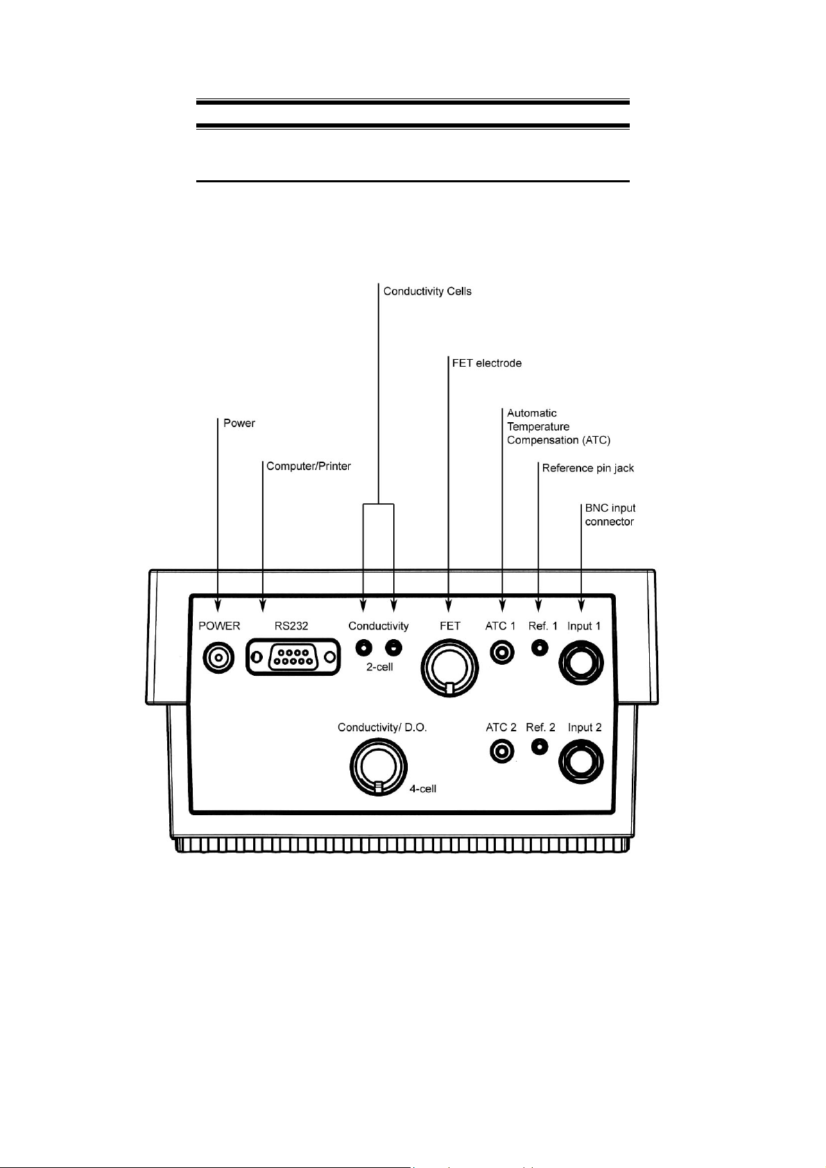
3.1 Connectors (PCD 5500 only)
1. Review the layout and arrangement of the rear connector panel.
Back Panel of PCD 5500
3
Page 9
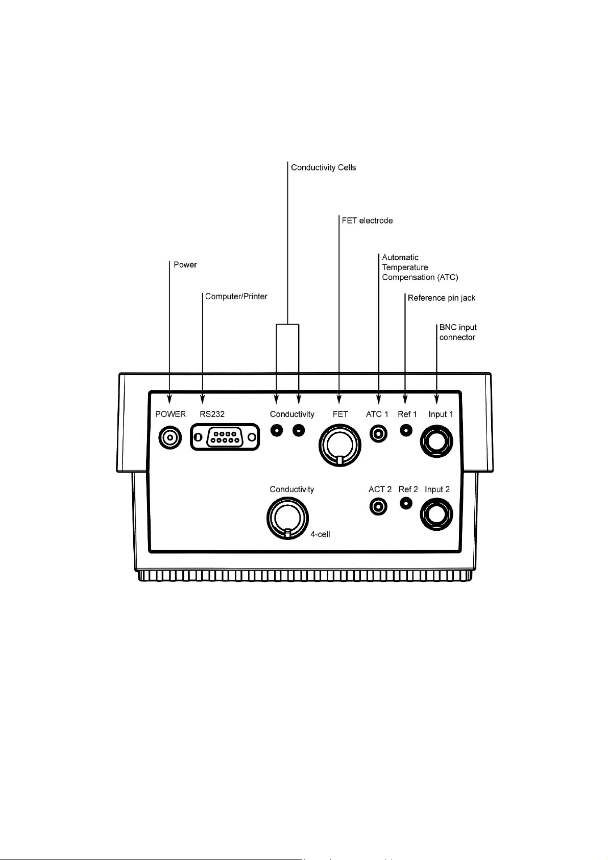
Instruction Manual CyberScan PC5500/ 5000
Back Panel of PC 5500/ 5000
4
Page 10
Instruction Manual CyberScan PC5500/ 5000
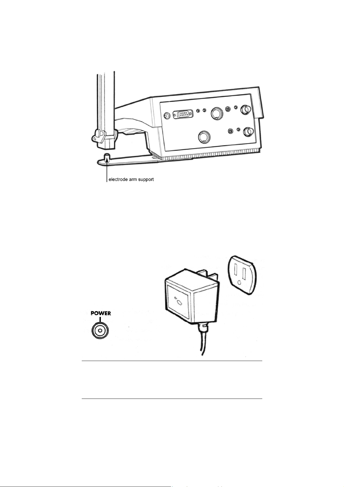
2. Connect the electrode arm to the base.
3. Connect the power cable to the connector cable to the rear
connector panel power jack and to a power source.
To connect RS232, see Data Management on Section 17.2.
5
Page 11
Instruction Manual CyberScan PC5500/ 5000
3.2 pH Electrodes & Ion Specific Electrodes (PCD5500 &
PC5500 only
This meter allows you to use two types of pH electrodes: the
conventional glass pH electrode and the field effect transistor (FET)
pH electrode. If both types of pH electrodes are connected, the meter
will read the FET electrode.
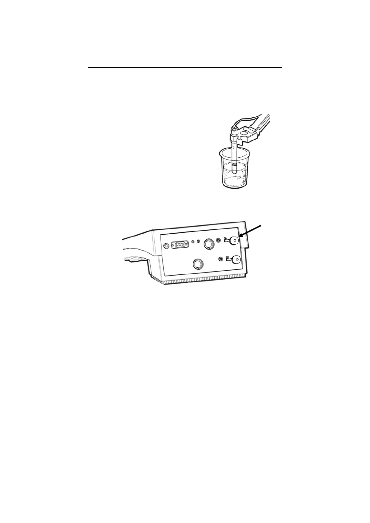
1. Carefully remove the protective
cover from the end of the electrode.
Before first using your glass pH
electrode, soak it 2-4 hours in an
electrode storage solution, pH 4
buffer, or KCI solution.
2. Remove the shorting cap on BNC connector. Connect the
combination pH electrode in to the BNC input connector.
If a combination electrode isn’t used, connect the indicating pH
electrode into the BNC input connector. Plug the reference
electrode into the reference pin jack. Also, install the ATC probe
into the ATC jack.
Note: be sure to connect all probes to the appropriate channel
connectors (for example: Input 1, Ref 1 and ATC1).
Option: Connect the optional FET electrode by plugging it into
the FET jack on the back meter panel. Allow the FET electrode to
warm up five minutes before use.
Connect ion specific electrodes in the same manner as pH
electrodes.
If both a conventional and a FET electrode are connected to the
meter, do not put them in a solution together because you will get
inaccurate measurements. Do not discard the BNC shorting cap.
6
Page 12
Instruction Manual CyberScan PC5500/ 5000
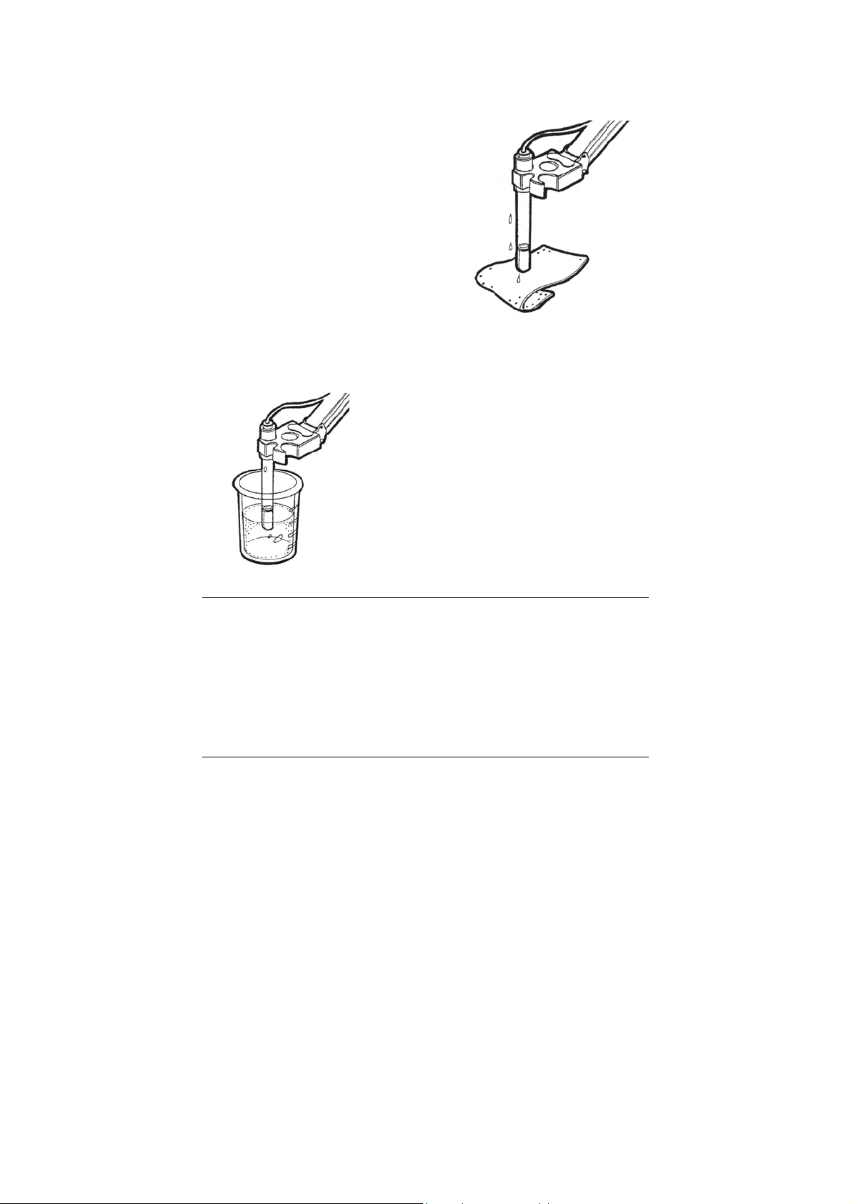
3. Rinse and blot-dry (don’t wipe)
electrodes between each
measurement. Rinse electrodes
with distilled or deionized water,
or a portion of the next solution
to be measured.
4. Between measurements, store
conventional pH electrodes
storage solution, pH 4 buffer, or
KCI solution. Always leave the
filling hole of liquid filled
combination electrodes open.
Refill when the level of
solution gets below the
manufacturer’s recommended
level.
Proper electrode care is fundamental to obtaining reliable pH
measurements. Improper care of the electrode may cause the meter
reading to drift, respond slowly, or produce erroneous readings. For
this reason, the electrode should always be conditional and used in
accordance with manufacturer’s instructions.
7
Page 13

Instruction Manual CyberScan PC5500/ 5000
3.3 Conductivity Probes
This meter allows you to use two types of conductivity cells: the 2-cell
conductivity cell with dual pin connector and the 4-cell conductivity
cell with DIN connector. If both a 2-cell and a 4-cell conductivity probe
are connected, the meter will read the 4-cell conductivity probe.
1. Carefully remove the protective
cover from the end of the
conductivity cell. Before using your
conductivity cell, soak it for 5 to 10
minutes in distilled or deionized
water.
2. Connect the 2-cell conductivity cell to the 2-cell jack. Install the
ATC probe in the ATC jack.
OR
Connect the 4-cell conductivity cell to the 4-cell jack. The 4-cell
conductivity cells have built in ATC probes. Therefore, there is
no need to install a separate ATC probe.
8
Page 14

Instruction Manual CyberScan PC5500/ 5000
3. Rinse and blot-dry (don’t wipe)
probe between each measurement.
Rinse probe with distilled or
deionized water, or a portion of the
next solution to be measured.
4. Between measurements, store
conductivity probes dry.
9
Page 15

Instruction Manual CyberScan PC5500/ 5000
4 USING THE METER
E U T E C H
INSTRUMENTS
11:11 am
Touch anywhere to resume
10
Page 16

Instruction Manual CyberScan PC5500/ 5000
4.1 Touch screen Operation
This new CyberScan research benchtop meter operates with a state
of art touch screen. The touch screen makes this the easiest meter
on the market to operate and care for. When this meter is first
plugged in, the STANDBY screen will appear. Touch anywhere on
this screen to access the functions of the meter.
The buttons on the right side of the screen control all of the functions
of the meter. Alight touch on the screen is all you need to access the
various functions. Once you touch a button you will get an audible
tone; the screen will not change until you lift your finger.
This design prevents rapid uncontrolled scrolling through the various
function screens. Easy to understand prompts guide you through the
operation of the meter in the selected mode. If you are ever in doubt
about what to do, just touch help on the bottom right corner of the
screen for detailed information about the screen.
The touch screen is made of a durable polyester material that is
chemically resistant. Maintenance is simple with this meter. To clean
the screen you just need to wipe it with a damp cloth and dry it with a
clean dry towel. For additional information, see cleaning and
troubleshooting section of the manual (page 149).
11
Page 17
Instruction Manual CyberScan PC5500/ 5000
J
J
n
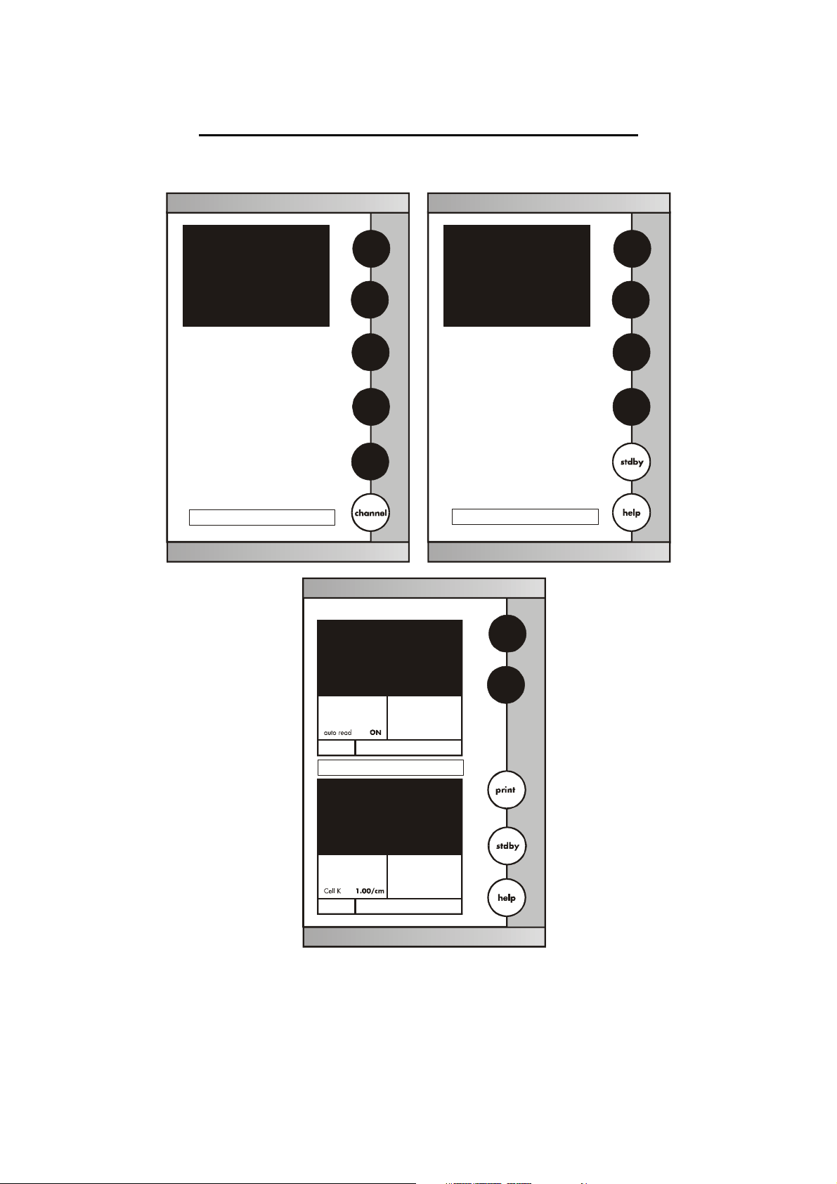
4.2 Choosing a channel (for PCD5500 & PC5500 only)
Main Scree
Channel Screen
E U T E C H
INSTRUMENTS
pH
E U T E C H
1
INSTRUMENTS
CyberScan PC 5500
Select from the options to the right
January 15, 2002 11:11 am
mV
Ion
Cond Cond
setup
Measure
pH channel 1
9.295
ID#
00000
auto buffer
Buffers
anuary 15, 2002 11:11 am
µS/cm channel 1
ATC
ON
slope
000.0%
mV
0000.0
Last std: Jan 15 @ 11:11
CyberScan PC 5500
Select from the options to the right
anuary 1 5, 2002 11:11 am
1
2
25.0°C
am
2
dual
0.010
ID#
00000
ATC
26.2°C
Ref
25°C
Co
0.00%/°C
STND
Last std: Jan 15 @ 11:11
Dual Screen
am
12
Page 18

Instruction Manual CyberScan PC5500/ 5000
The CyberScan PCD5500/ PC5500 are multi-channel meters. With
this meter you can switch from channel 1 to channel 2. You can also
view both channels at the same time by accessing the dual channel
mode. If you set the meter to view both channels, you cannot change
the parameters without choosing the screen that you want to modify.
The setup parameters for each screen independently of one another.
Choosing a channel
1. Touch anywhere on the standby screen.
OR
Touch channel on the main screen
THEN
2. Touch 1, 2 or dual to access the channel that you want to view.
To access System Setup from the standby screen
1. Touch anywhere on the standby screen.
2. Touch 1, 2 or dual to access the channel that you want to view.
3. Touch setup.
4. Touch system on the setup screen.
If you are in any measure made, touch mode until you access the
main screen.
13
Page 19
Instruction Manual CyberScan PC5500/ 5000
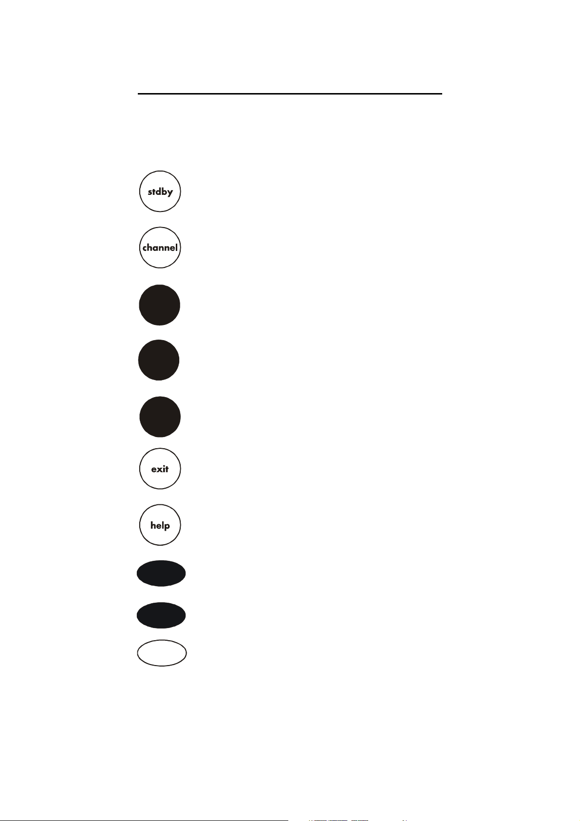
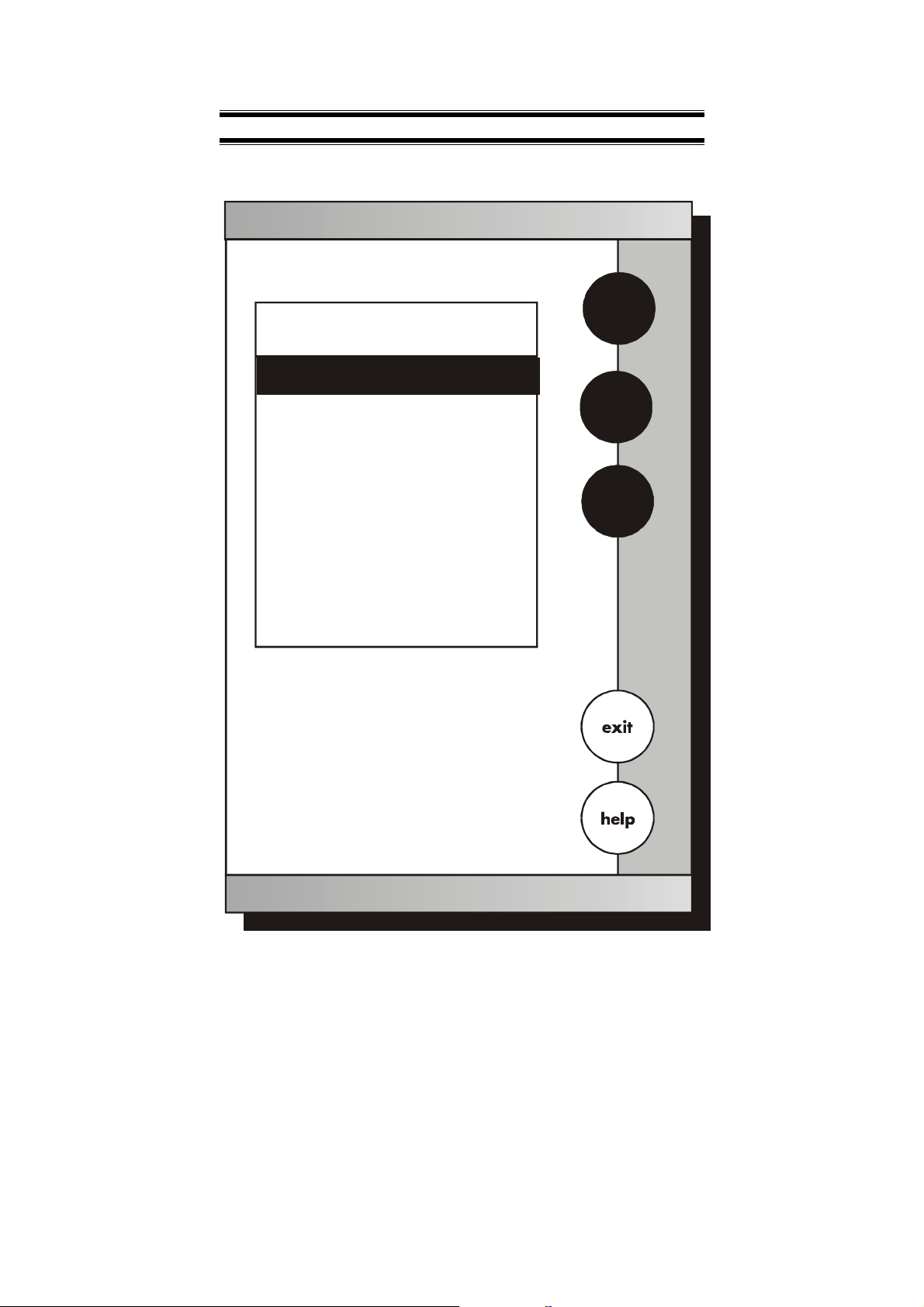
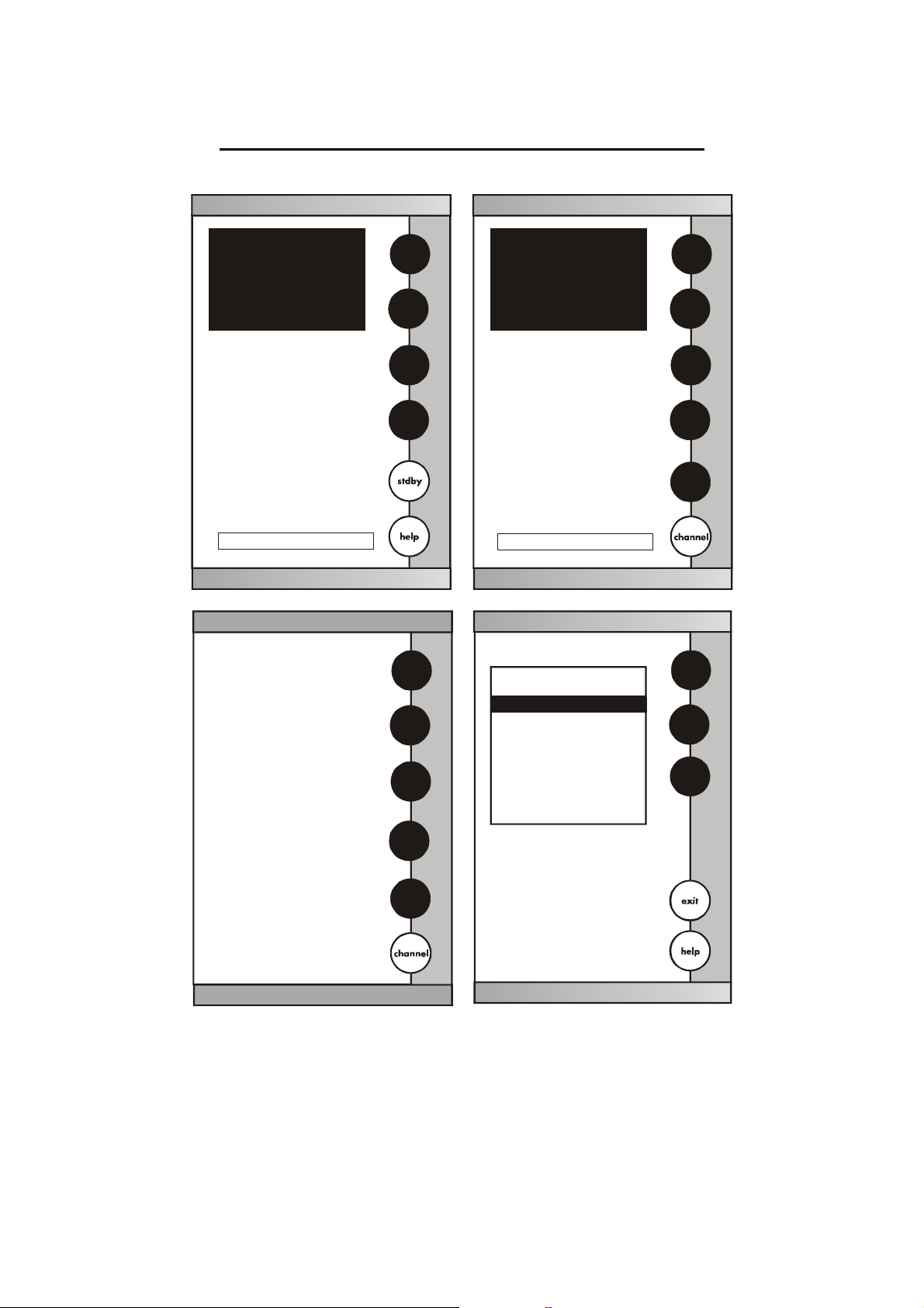
4.3 Button Functions
The touch screen of your CyberScan bench meter has “buttons”
along the right side of the screen that are common to many of the
screens. The following indicates the function of these common
buttons.
This is the standby button and it allows you to access the
standby mode. When in standby, the meter will not take
measurements. It is in a state of rest. When you touch stdby
the meter will return to the standby screen which says “Eutech
Instruments” and displays the time.
This button allows you to access the channel screen to choose
what channel you want to view. This button appears only on
dual-channel meters such as PC 5500 and PCD 5500. This
button also allows you to move from the main mode to the
channel screen to access the standby mode.
The mode button allows you to switch between the various
mode
enter
save
close
more
back
operations of the meter. These operations, depending upon
which meter you have, include four measuring modes (pH, mV,
ion and conductivity) as well as a setup mode.
The enter button allows you to accept any changes that you
have made on one setup screens or accept values that you
have input with keypads. When touched, enter will save the
changes and return you to the previous screen.
The save button allows you to save multiple changes that you
have made on one screen as a group. It functions like the enter
button does for an individual changes.
The exit button allows you to leave the screen you are
currently viewing and return to the previous screen without
making any changes.
The help button allows you to access helpful information on
any screen. When you touch the help button, information about
the current screen appears. This information will include step
by step instructions for operating the meter from the current
screen and possible applications information for that screen.
The close key appears on the bottom of all help screens and
allows you to exit the help screen and return to the previous
screen.
The more button appears on the help screens and allows you
to advance to the next help screen for additional information.
The back button appears on the help screen and allows you to
move back to a previous help screen.
14
Page 20

Instruction Manual CyberScan PC5500/ 5000
This button accesses the standardization screen from the
std
meas
setup
print
S
edit
clear
BS
BS
delete
prev
next
various measurement modes and initiates standardization of
the meter once the standardization screen is accessed.
This button is the measure button and directs the meter to
measure your sample when in the Auto Read function of the
pH mode.
This button will access the setup screens for the measuring
mode that you are currently using. It can also be used to
access the system setup screen that allows you to set
parameters that are not related to measurements such as the
times and the date.
The print button will send information to the output device that
you have connected to your CyberScan meter. The output
device can be a printer, data logger or a computer. In addition
to this, touching the print button will also send data to the data
storage center of the meter if a sample ID # has been assigned
to your sample.
The arrow keys on he screen move the cursor up and down in
order to highlight parameters that you would like to review or
edit.
The edit button appears on the setup screens. After you have
highlighted a parameter that you would like to change, the edit
button allows you to access the available options for that
parameter.
The clear button allows you to remove a setup parameter or
standard buffer value from the meter’s memory that may have
been entered at a previous time or by a previous user that is no
longer of value to you. Touching the clear button erases the
value so you may enter a new one. It can also erase the data
from the memory of the meter.
The BS button is a backspace button. It appears on keypad
screens and it allows you to back up and delete a character
entered in error.
The delete button appears on the “View Stored Data” screens.
This button allows you to erase the data from the memory of
the meter.
The prev button appears on the Data Screens when the data
stored in the meter’s memory has been accessed. It allows you
to scroll through data points sorted and stored prior to the
current data point displayed.
The next button appears on the Data Screens when the data
stored in the meter’s memory has been accessed. It allows you
to scroll through data points sorted and stored prior to the
current data point displayed.
15
Page 21
Instruction Manual CyberScan PC5500/ 5000
5 SYSTEM SETUP
System Setup
S
SYSTEM SETUP OPTIONS
-
Select
Language
- Set
Date
T
Time
- Set
- Set
Beeper Status
- Set
Print Configuration
edit
- Set
Operator
- Set
Display Contrast
- Display
- Reset to
Meter Information
Factory Defaults
16
Page 22
Instruction Manual CyberScan PC5500/ 5000
J
5.1 Access system setup
E U T E C H
INSTRUMENTS
1
E U T E C H
INSTRUMENTS
pH
CyberScan PC 5500
Select from the options to the right
January 15, 2002 1 1:11 am
Setup
Select from the options to the right
2
dual
Cond Cond
pH
mV
Ion
CyberScan PC 5500
Select from the options to the right
anuary 15, 2002 11:11 am
System Setup
SYSTEM SETUP OPTIONS
- Selec t
Language
- Set
Date
Time
- Set
- Set
Beeper S tatus
- Set
Print Configuration
- Set
Operator
- Set
Display Contrast
- Disp lay
Mete r Infor matio n
- Rese t to
Factory Defaults
mV
Ion
setup
S
T
edit
Cond
setup
17
Page 23

Instruction Manual CyberScan PC5500/ 5000
The system setup function allows you to customise the meter display
options to meet your personal preference. Once set, these will rarely
need to be changed.
To access System Setup
1. Touch anywhere on the standby screen
2. Touch setup on the main screen
3. Touch system on the setup screen
The system setup options are now displayed on the screen.
To access a System Setup option
1. Use the arrow keys to scroll through the setup options and
highlight the option to be reviewed.
2. Touch edit to view the current status of the selected option.
The following is a detailed description of the system setup option
screens
18
Page 24
Instruction Manual CyberScan PC5500/ 5000
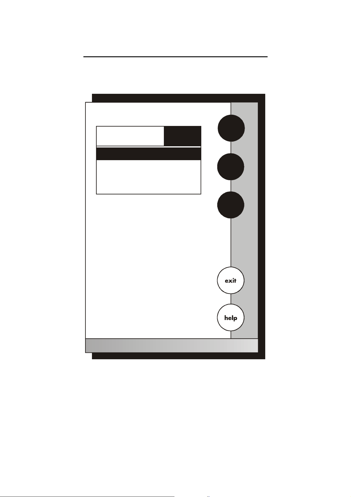
5.2 Select Language
Set
Language
Current LANGUAGE
English
French
German
Spanish
Use to highlight desired language
arrow keys
and then touch to accept
enter
English
S
T
enter
19
Page 25

Instruction Manual CyberScan PC5500/ 5000
This option allows you to choose the language in which all prompts
and directions will appear on the touch screen.
To Select Language
1. Access the select language screen from the system setup
screen. The current language is displayed on the screen.
2. Use the arrow keys to highlight the desired language
3. Touch enter to accept the language and return to the system
setup screen.
OR
Touch exit to return to the system setup screen, without making
any changes.
20
Page 26
Instruction Manual CyberScan PC5500/ 5000
5.3 Set Date
Set
Date
enter
Current MM/DD/YY
1 2 3
4 5 6
7 8 9
BS 0 /
Touch clear to delete current date
Use numeric touchpad to input the new
date and then touch enter to accept
D/M/Y
clear
21
Page 27

Instruction Manual CyberScan PC5500/ 5000
This screen can be used to set the present date which will be
displayed on the measure screens. This date will also be printed on
demand and stored in the data storage center of the meter when data
is saved. There are two format options for the date: month/ day/ year
(M/ D/ Y) or the European format of day/ month/ year (D/ M/ Y)
To Set Date
1. Access the Set Date screen from the System Setup screen. The
current date and numeric keypad are displayed on the screen.
2. Touch clear to delete the current entry.
3. Touch D/ M /Y or M/ D/ Y to set the date format.
4. Use the numeric touch pad to enter the desired date, separating
the day, the month and the year by touching the / key on the
keypad.
5. Touch enter to accept the date in the current format.
OR
Touch exit to return to the system setup screen, without making
any changes.
If you do not use “/”, the meter will not accept the date entry.
22
Page 28
Instruction Manual CyberScan PC5500/ 5000
5.4 Set Time
Set
Time
enter
Current 12HR:
10:40 am
1 2 3
4 5 6
7 8 9
BS 0 /
Touch to delete current time
clear
Use to input the new
numeric touchpad
time and then touch to accept
enter
24hr
pm
clear
23
Page 29

Instruction Manual CyberScan PC5500/ 5000
This screen can be used to set the present time which will be
displayed on the measure screens. This time will also be printed on
demand and stored in the data storage center of the meter when data
is saved. There are two formats options for the time. The clock can
be set as either a 12 hour clock or a 24 hour clock.
To Set Time
1. Access the set time screen from the System Setup screen. The
current time and numeric keypad are displayed on the screen.
2. Touch clear to delete the current entry.
3. Touch the 24hr or 12hr button to format the clock as either a 12
hour or a 24 hour clock.
4. Touch am or pm to set the appropriate time.
5. Use the numeric touch pad to enter desired time, separating the
hour and the minutes by touching the “
6. Touch enter to accept the time in the current format
OR
Touch exit to return to the System Setup screen, without making
any changes.
Current 12HR
Current 24HR
5:15 pm
17:15
:” key in the keypad.
If you do not use the “:”, the meter will not accept the time.
24
Page 30
Instruction Manual CyberScan PC5500/ 5000
5.5 Set Beeper Status
Set
Beeper Status
S
Current BEEPER STATUS
-
After STABLE Readin
OFF
- After KEY Touch
- On LIMIT Exceeded
Use to highlight beeper
arrow keys
option and then touch to
change
Touch to accept changes
save
ON/OFF
OFF
OFF
T
ON
save
25
Page 31

Instruction Manual CyberScan PC5500/ 5000
This screen allows you to turn on or off the beeper. You may choose
to have an audible signal when the meter recognises that the current
measurement is stable, each time a function button is touched and/ or
when the set limits of a measurement mode have been exceeded.
After stable reading
When active, the meter delivers an audible tone each time the meter
recognises the current measurement as stable. If deactivated, you
will not hear an audible tone at a stable measurement. You will still
see the STABLE indicator even if there is no audible tone.
After key activation
When active, the meter delivers an audible tone each time you touch
a function button or a key on an alphanumeric keypad. If deactivated,
you will not hear a tone after a key touch. The changes will only be
visible on the screen.
On LIMIT Exceeded
When active, the meter delivers an audible tone each time the set
limits in a measurement mode have been exceeded. If deactivated,
you will not hear an alarm tone when the limits in the measurement
modes have been exceeded. You will see the LIMIT indicator on the
measurement screen. For additional information on the alarm limits of
the meter, see the setup sections of this manual for each of the
measurement modes.
To Set Beeper Status
1. Access the set beeper status screen from the System Setup
screen. The current beeper status is displayed on the screen.
2. Use the arrow keys to highlight the beeper status option that you
would like to modify.
3. Touch ON or OFF until the desired status is visible in the current
beeper status box.
4. Touch save to accept the change sand return to the System
Setup screen.
OR
Touch exit to return to the System Setup screen without making
any changes.
26
Page 32

Instruction Manual CyberScan PC5500/ 5000
5.6 Select procedural level
Select
Procedural Level
Current LEVEL
LEVEL 1
LEVEL 2
1
- Basic Level
- Advanced Level
Procedural Level 1
January 15, 2002 11:11am
enter
1
2
Temperature
Electrode Performance
25.0°C
100%
Procedural Level 2
January 15, 2002 11:11am
ID#
00000
auto buffer
ON
27
ATC
slope
mV
25.0°C
100%
0000.0
Page 33

Instruction Manual CyberScan PC5500/ 5000
This selection screen allows you to choose the amount of information
that you want to have displayed on the screen. There are two levels
to choose from. Both of the levels provide identical results. The
amount of information appearing on the measure screens and the
number of setup parameters you can manipulate will vary from Basic
to Advanced procedural levels.
LEVEL1- Basic level
This level option offers a full set of prompts to guide you through the
basic operation of the meter. The information provided on the screen
is minimal to reduce clutter. It includes the measurement and the last
standardization time and buffer values. The data box at the bottom of
the measure screen includes the current date, time, sample
temperature and the electrode performance. In addition to the limited
information appearing on the measure screen, there are also fewer
options available to you in the setup screens of the various
measurement modes.
LEVEL 2- Advanced level
This option allows you to access to all of the features available on the
meter. A full set of prompts is available on virtually every screen to
lead you through the operation of the meter. You are also given
access to all setup parameters for the various measurement modes.
Any parameter not appearing on the basic level setup screens will
maintain the value previously set in the advanced level setup
screens. They will not automatically default to factory default settings.
This is ideal if you want to “lock” in a parameter in the Advanced
Level and switch to the Basic Level so others cannot accidentally
modify the parameters.
To Select Procedural Level
1. Access the select procedural level screen from the System Setup
screen. The current procedural level is displayed on the screen.
2. Use the numbered buttons on the right of the screen to select the
desired procedural level.
3. Touch enter to accept the procedural level and return to the
System Setup screen.
OR
Touch exit to return to the System Setup screen, without making
any changes.
28
Page 34

Instruction Manual CyberScan PC5500/ 5000
5.7 Set Print Configuration
Set
Print Configuration
S
Current PRINT CONFIGURATION
- Baud Rate
- # of Bits
- # of Stop
- # Parity
Use to highlight desired
print setting and then touch to
change
Touch to save the print settings
NONE
arrow keys
save
19200
edit
8
1
T
edit
save
29
Page 35

Instruction Manual CyberScan PC5500/ 5000
You can adjust the print configuration of this meter from this screen.
The configuration of the following screens must match the
configuration of the printer or computer to which the data will be sent.
To Set Print Configuration
1. Access the Print Configuration screen from the System Setup
screen. The current Print Configuration is displayed on the
screen.
2. Use the arrow keys to highlight the configuration option to be
modified.
3. Touch edit to access the parameters for the highlighted option
OR
Touch exit to return to the system Setup screen, without making
any changes.
30
Page 36

Instruction Manual CyberScan PC5500/ 5000
5.8 Set Baud Rate
This configuration option will control the speed at which the data will
be transmitted by the printer. This parameter needs to match the
baud rate designated by the printer or computer.
To Set Baud Rate
1. Access the Set Baud Rate screen from the Set Print
Configuration screen. The current baud rate is displayed on the
screen.
2. Use the arrow keys to highlight the baud rate option that
matches the baud rate of your printer or computer.
3. Touch enter to accept the baud rate and return to the Set Print
Configuration screen.
OR
Touch exit to return to the Set Print Configuration screen, without
making any changes.
Set
Baud Rate
Current BAUD RATE
9600
110
300
600
1200
2400
4800
9600
9600
19200
38400
S
T
enter
31
Page 37

Instruction Manual CyberScan PC5500/ 5000
5.9 Set Number of Bits
To Set Number of Bits
1. Access the Set number of Bits screen from the Set Print
Configuration screen. The current number of bits is displayed on
the screen.
2. Touch 7 or 8 to select the number of bits.
3. Touch enter to accept the bit value and return to the Set print
Configuration screen.
OR
Touch exit to return to the Set Point Configuration screen, without
making any changes.
Set
Number of Bits
Current NUMBER OF BITS
enter
7
8
32
Page 38

Instruction Manual CyberScan PC5500/ 5000
5.10 Set Stop Bits
To Set Stop Bits
1. Access the Set Stop Bits screen from the Set Print Configuration
screen. The current number of bits is displayed on the screen.
2. Touch 1 or 2 to set the desired number of stop bits.
3. Touch enter to accept the stop bit value and return to the Set
Print Configuration screen.
OR
Touch exit to return to the Set Print Configuration screen, without
making any changes.
Set
Stop Bits
Current STOP BITS
enter
1
2
33
Page 39

Instruction Manual CyberScan PC5500/ 5000
5.11 Set Parity
To Set Parity
1. Access the Set Parity screen from the Set Print Configuration
screen. The current Parity is displayed on the screen.
2. Touch ODD or EVEN or NONE to set the desired parity.
3. Touch enter to accept the parity setting and return to the Set
Print Configuration screen.
OR
Touch exit to return to the Set Print Configuration screen, without
making any changes.
Set
Parity
Current PARITY
enter
NONE
EVEN
ODD
34
Page 40

Instruction Manual CyberScan PC5500/ 5000
A
Y
5.12 Set Operator
Set
Operator
enter
Current Operator
B C 1
D E F 2
G H I 3
J K L 4
M N O 5
P Q R 6
S T U 7
V W X 8
Z - 9
BS / . 0
clear
35
Page 41

Instruction Manual CyberScan PC5500/ 5000
This option allows you to identify the user of the meter. This
information can be saved in the meter’s memory. It can also be
printed out with measurement data on demand. The operator
identification can be up to 9 characters in length.
To Set Operator
1. Access the Set Operator screen from the System Setup screen.
The current operator identification is displayed on the screen.
2. Touch clear to remove the current operator identification.
3. Use the alphanumeric keys on the touch screen to enter the
desired operator identification. The BS button will allow you to
backspace to remove a character that was incorrectly entered.
The operator identification code can be a maximum of 9
characters in length.
4. Touch enter to accept the new operator identification.
OR
To deactivate the operator identification:
a) Touch clear to erase the current user identification.
b) Touch enter to return to the System Setup screen.
OR
Touch exit to return to the System Setup screen.
OR
Touch exit to return to the System Setup screen, without making
any changes.
36
Page 42

Instruction Manual CyberScan PC5500/ 5000
5.13 Set Display Contrast
Set
Display Contrast
lighter
darker
17
Touch or to adjust
lighter darker
contrast and then touch to accept
The value displayed ranges from
0(darkest) to 25 (lightest)
save
save
37
Page 43

Instruction Manual CyberScan PC5500/ 5000
This option allows you to change the contrast on the screen to
improve the readability of the information presented on the screen.
The numbering system that appears on the screen is from 0 to 25.
The darkest setting is 0 and the lightest setting is 25.
To Set Display Contrast
1. Access the Set Display Contrast screen from the System Setup
screen. The current display contrast value is displayed on the
screen.
2. Use the lighter or darker button to adjust the contrast of the
screen to the desired level.
3. Touch save to accept the contrast setting and return to the
System Setup screen.
OR
Touch exit to return to the System Setup screen, without making
any changes.
The display contrast of the screen is affected by the internal
temperature of the meter. The meter will warm up after being plugged
in. during this period (approximately 20 minutes), the display contrast
of the screen will get lighter. You may need to adjust the contrast
during this period to meet your specifications.
38
Page 44

Instruction Manual CyberScan PC5500/ 5000
5.14 Display Meter Information
This screen displays the model number, serial number and current
software revision of your meter.
E U T E C H
INSTRUMENTS
11:11 am
Unit Serial Number: XX999XXX
Software Revision: 1.04b
39
Page 45

Instruction Manual CyberScan PC5500/ 5000
Y
5.15 Reset to Factory Defaults
This screen allows you to reset all functions and setup parameters of
the meter of the settings originally programmed at the factory.
To Reset to Factory Defaults
1. Access the Reset to Factory Defaults screen from the System
Setup screen.
2. Touch Yes to reset all parameters to the original factory default
settings.
OR
Touch NO to return to the System Setup screen, without making
any changes.
Reset to Factory Defaults
You are about to reset all parameters of the meter
to factory default settings.
Are you sure you want to do this?
ES
NO
40
Page 46

Instruction Manual CyberScan PC5500/ 5000
6 pH SETUP
pH Setup
pH SETUP OPTIONS
- Set
Sample ID#
- Select
- Select
- Select
- Set
- Set
- Set
- Set
- Set
- Set
- Set
- Set
- Set
- View
Buffer Group
Buffer Recognition
Auto Read Mode
pH Stability Criteria
Default Temperature
Isopotential Point
Alarm Limits
Print Criteria
Print Interval
Data Storage Criteria
Display Resolution
Display Configuration
Stored Data
S
T
edit
The operating parameters of the pH mode can be set and controlled
from the pH setup screen. The following sections will guide you
through the various options available in the pH setup mode.
41
Page 47

Instruction Manual CyberScan PC5500/ 5000
6.1 Access pH setup
E U T E C H
INSTRUMENTS
CyberScan PC 5000
Select from the options to the right
Last std: Jan 15 @ 11:11 am
pH Setup
pH SETUP OPTIONS
- Set
Sample ID#
- Select
Buffer Gro up
-
Selec t
Buffer Recognition
- Select
Auto Read Mode
- Set
pH Stability Criteria
- Set
Default Temperat ure
- Set
Isopotential Point
- Set
Alarm Limits
- Set
Print Criteria
- Set
Print Inter val
- Set
Data Storage Criteria
- Set
Display Resolution
- Set
Display Configuration
- View
Stored Dat a
pH
mV
Ion
Cond Cond
setup
Setup
Select from the options to the right
pH
mV
Ion
system
There are two ways to access the
S
pH Setup screen.
From the setup screen
T
1. Touch setup on the main
screen. Touch pH to access
the pH Setup screen.
edit
2. Use the arrow keys to highlight
the setup option that you would
like to review
3. Touch edit to access the
screen for the selected option.
42
Page 48

Instruction Manual CyberScan PC5500/ 5000
J
E U T E C H
INSTRUMENTS
CyberScan PC 5000
Select from th e options to the right
Last std: Jan 15 @ 11:11 am
pH
mV
Ion
Cond
setup
Measure
pH
7.00
7
BUFFERS
or
Last std: Jan 15 @ 11:11 am
Touch to measure sample
meas
Touch to access standardize
std
anuary 15, 2002 11:11am
00000
ID#
auto buffer
ON
ATC
Slope
mV
channel 1
25.0°C
NA
0000.0
std
meas
From the pH measure screen
1. Touch pH on the main screen to
access the pH mode. Touch setup
option that you would like to
review.
2. Use the arrow keys to highlight the
setup option that you would like to
review
3. Touch edit to access the screen
for the selected option.
pH Setup
pH SETUP OPTIONS
- Set
Sample ID#
- Select
Buffer Group
-
Select
Buffer Recognition
- Select
Auto Read Mode
- Set
pH Stability Criteria
- Set
Defaul t Temperature
- Set
Isopotential Point
- Set
Alarm Limits
- Set
Print Criteria
- Set
Print Interval
- Set
Data Storage Criteria
- Set
Display Resolution
- Set
Display Configuration
- View
Stored Data
S
T
edit
43
Page 49

Instruction Manual CyberScan PC5500/ 5000
A
Y
6.2 Set Sample ID#
Set
pH Sample ID#
enter
Manual ID#
B C 1
D E F 2
G H I 3
J K L 4
M N O 5
P Q R 6
S T U 7
V W X 8
Z - 9
BS / . 0
clear
44
Page 50

Instruction Manual CyberScan PC5500/ 5000
When this option is active, each time you touch print on the
Measure screen the pH value along with the date/ time/ channel
and the sample ID# will be sent to data storage. (for additional
information on saved parameters). You can manually enter an
alphanumeric identification number of up to 9 characters for any
sample or you can have the meter sequentially number your
samples beginning at the number of your choice. You may
choose to deactivate the sample ID#.
To Set Sample ID#
Manual ID# Assignment
1. Access the Set Sample ID# screen from the pH (mV, Ion,
Conductivity) Setup screen.
2. Touch man for manual ID# entry. The current ID# is
displayed on the screen.
3. Touch clear to delete the current ID#.
4. Use the alphanumeric keypad on the screen to meter the
desired Sample ID#. The BS Key will allow you to backspace
to remove a character that was incorrectly entered.
5. Touch enter to accept the current ID# and return to the pH
(mV, Ion, Conductivity) Setup screen.
45
Page 51

Instruction Manual CyberScan PC5500/ 5000
Set
pH Sample ID#
enter
Sequential ID#
1 2 3
4 5 6
7 8 9
BS 0 .
Touch to delete current ID
clear
Use to input the new
numeric touchpad
starting ID and then touch to accept
enter
24hr
clear
46
Page 52

Instruction Manual CyberScan PC5500/ 5000
Sequential ID# Assignment
1. Access the Set Sample ID# screen from the pH (mV, Ion,
Conductivity) Setup screen.
2. Touch seq for sequential ID# assignment. The current ID# is
displayed on the screen.
3. Touch clear to delete the current ID#.
4. Use the alphanumeric keypad on the screen to enter the number
that you would like your sequential ID# assignment to begin with.
Every time you touch print on the measure screen, the ID# will
increase by 1. The BS key will allow you to backspace to remove
a character that was incorrectly entered.
5. Touch enter to accept the first sequential ID# and return to the
pH (mV, Ion, Conductivity) Setup screen.
OR
To Deactivate the Sample ID# Assignment
1. Access the Set Sample ID# screen from the pH (mV, Ion,
Conductivity) Setup screen.
2. Touch man for manual ID# entry. The current ID# is displayed on
the screen.
3. Touch clear to delete the current ID#.
4. Touch enter. The ID# assignment is now deactivated. No number
will be assigned to your samples. The meter will return to the pH
(mV, Ion, Conductivity) Setup screen.
OR
Touch exit to return to the pH (mV, Ion, Conductivity) Setup
screen, without making any changes.
47
Page 53

Instruction Manual CyberScan PC5500/ 5000
6.3 Select Buffer Group
View
pH Buffer Group
enter
Current Buffer Group
USA
2 4 7 10 12
Use to display desired buffer group
keys
and then touch to accept
enter
EURO
NIST
custom
48
Page 54

Instruction Manual CyberScan PC5500/ 5000
This setup option allows you to select from 3 different buffer groups
each containing 5 buffers, for auto buffer recognition. Or you can
create a custom group of buffers for auto buffer recognition by
touching custom.
The 3 existing buffer groups are:
USA buffers: 2,4,7,10 and 12
European buffers: 1,3,6, 8 and 10
NIST buffers: 1.68, 4.01. 6.86. 9.18 and 12.45
To Select Buffer Group
1. Access the select pH buffer group screen from the pH Setup
screen. The current buffer group is displayed on the screen.
2. Touch USA or NIST or EURO or custom on the right of the
screen to select a buffer group
3. Touch enter to accept the buffer group to be used for auto
recognition.
OR
Touch exit to return to pH Setup Screen, without making any
changes.
49
Page 55

Instruction Manual CyberScan PC5500/ 5000
6.4 Set pH Custom Buffer Group
View
pH Custom Buffer Group
Current BUFFER GROUP
CUSTOM
enter
View
pH Custom Buffer Group
Current BUFFER GROUP
CUSTOM
W
Use to display desired buffer group
keys
and then touch to accept
enter
View
edit
pH Custom Buffer Group
Current BUFFER GROUP
CUSTOM
1.78 3.65
Use to display desired buffer group
keys
and then touch to accept
enter
enter
edit
X
edit
enter
Use to display desired buffer group
keys
and then touch to accept
enter
50
Page 56

Instruction Manual CyberScan PC5500/ 5000
To Set pH Custom Buffer Group
This option allows you to create a custom buffer group of up to 5
buffers to be used for auto buffer recognition. To obtain optimal
results, it is important to maintain at least 2 pH units between
selected buffers in the custom group.
1. Touch custom on the Set pH Buffer Group screen. The current
buffer box will show the current custom buffer group.
2. Touch edit to alter the present group or create a new custom
buffer group. The newly displayed Set pH Custom Buffer Group
screen has 5 beakers in the current buffer group box.
3. Use the arrow keys to highlight the beaker icon with the pH
value you want a change. If there are no buffers in the group then
proceed to the next step.
4. Touch edit to add a buffer or make changes to the current buffer
group OR touch clear to delete the highlighted buffer value.
5. Use the numeric keypad that is now displayed to enter the pH
buffer value that you want ion your custom buffer set.
6. Touch enter to accept the value. If you have entered an
erroneous value, use the BS key on the keypad to erase the last
digit entered and correct the mistake. If you decide not to change
the buffer value on the highlighted beaker icon, touch exit on the
numeric keypad to return to the Set pH Custom Buffer Group
screen.
7. Repeat steps 3 through 6 to add up to 5 buffers to your custom
buffer group.
8. Touch exit to return to the Set pH Custom Buffer Group screen to
view the current Custom Buffer Group, without making any
changes to the custom buffer group.
9. Touch enter to accept the group and return to the pH Setup
screen, OR touch edit to modify the group and repeat steps 3
through 6.
OR
Touch exit to return to the Set pH Buffer Group screen, without
making any changes to the custom buffer group.
If you use the custom buffer group for auto buffer recognition, when
you access the Set pH Buffer Group from the pH Setup screen, the
current buffer group that appears on the screen is the custom buffer
group. In order to access the edit option for the custom buffer group,
you need to touch any of the other buffer group buttons and then
touch custom to access the edit screen.
51
Page 57

Instruction Manual CyberScan PC5500/ 5000
6.5 Select Buffer Recognition
This option allows you to select automatic buffer recognition or
manual buffer recognition when standardizing. With the Automatic
buffer recognition activated, the meter will automatically recognise the
buffers from the chosen buffer group and accept them when the
meter recognises the reading as stable.
When in the manual buffer recognition mode, you must enter the
buffer value during the standardization procedure. The meter will
accept the manually entered buffer when it recognises that the
measurement is stable. During the standardization procedure, you
may accept the buffer value before the meter recognises it as stable
by touching std.
To Select Buffer Recognition
1. Access the select buffer recognition screen from the pH setup
screen. The current method of recognition is displayed on the
screen.
2. Touch MAN or AUTO to choose the method of buffer selection.
3. Touch enter to accept the method of buffer recognition and
return to the pH Setup screen.
OR
Touch exit to return to the pH setup screen, without making any
changes.
Set
pH Buffer Recognition
enter
Current RECOGNITION
AUTO
MAN
Regardless of which buffer Recognition Mode you select, STABLE
will appear on the measure screen when the meter recognises the
value as stable.
52
Page 58

Instruction Manual CyberScan PC5500/ 5000
6.6 Select Auto Read Mode
You can use this meter when the Auto Read Mode function is active
or when it is inactive. When the Auto Read function is active, the
meter will lock onto a reading when the meter recognises it as stable.
The meter will not deviate from this reading until meas is touched. If
the auto Read function is inactive, then the meter will continuously
monitor the pH of the sample and the Measure screen display will
indicate any fluctuation in the sample pH.
To Select Auto Read Mode
1. Access the Select Auto Read Mode screen from the pH Setup
screen. The current Read Mode id displayed on the screen.
2. Touch AUTO or MAN to choose the desired read mode.
3. Touch enter to accept the read mode and return to the pH setup
screen.
OR
Touch exit to return to the pH Setup Screen, without making any
changes.
Set
pH Auto Read Mode
Current MODE
enter
AUTO
MAN
53
Page 59

Instruction Manual CyberScan PC5500/ 5000
6.7 Set pH Stability Criteria
Set
pH Stability Criteria
Current CRITERIA
Fast
Medium
Slow
Use to highlight stability
arrow keys
criteria and then touch to accept
Medium
enter
S
T
enter
54
Page 60

Instruction Manual CyberScan PC5500/ 5000
This setup screen allows you to determine how quickly the meter will
respond to electrode drift. There are 3 speed settings: fast, medium
and slow.
To set pH Stability Criteria
1. Access the Set pH Stability Criteria screen from the pH (Ion)
Setup screen. The current stability criteria are displayed on the
screen.
2. Use the arrow keys to highlight the desired stability criteria.
3. Touch enter to accept the stability criteria and return to the pH
(Ion) Setup screen and return to the pH Setup screen.
OR
Touch exit to return to the pH (Ion) Setup screen, without making
any changes.
Stability criteria are more stringent at the slower setting. Therefore, if
the highest precision is required, then a slow setting would be
desired. The default setting is the medium speed and this would be
adequate for the majority of applications.
55
Page 61

Instruction Manual CyberScan PC5500/ 5000
6.8 Set Default Temperature
Set
pH Default Temperature
enter
Current DEFAULT
1 2 3
25.0°C
4 5 6
7 8 9
BS 0 .
Touch to delete current default temp
clear
Use to input the new
numeric touchpad
temperature and then touch to accept
enter
clear
56
Page 62

Instruction Manual CyberScan PC5500/ 5000
It is a well known fact that pH is a temperature dependent
measurement. The factory default setting is 25. if you are taking the
pH of a solution that is not 25 and you are not using an Automatic
Temperature Compensation (ATC)( probe, then you should meter the
temperature value of that solution in order to get the correct pH value.
The current default temperature setting will be displayed when the
Set Default Temperature screen is displayed.
To Set the Default Temperature
1. Access the Set Default Temperature screen from the pH (Ion,
conductivity) Setup screen. The current default temperature is
displayed on the screen.
2. Touch clear to erase the current temperature value.
3. Select the temperature units by touching the appropriate unit key
C (Celsius), F (Fahrenheit) or K (Kelvin).
4. Use the numeric keypad to enter the desired default temperature.
5. Touch enter to accept the temperature setting and return to the
pH (Ion, conductivity) Setup screen.
OR
Touch exit to return to the pH (Ion, conductivity) Setup screen,
without making any changes.
The use of an ATC probe provides a measured temperature value to
the meter and will override any value entered in the default
temperature screen. This measured value will be used by the meter
to make pH(Ion, conductivity) calculations.
57
Page 63

Instruction Manual CyberScan PC5500/ 5000
6.9 Set Isopotential Point
Set
pH Isopotential Point
enter
Current ISO POINT
1 2 3
0.0 mV
4 5 6
7 8 9
BS 0 .
Touch to delete current Iso Point
clear
Use to input the new
numeric touchpad
Iso Point and then touch to accept
enter
clear
58
Page 64

Instruction Manual CyberScan PC5500/ 5000
The Isopotential point is the millivolts reading for an electrode at
which temperature has no effect on the measurement. pH electrodes
are constructed so that the isopotential point is theoretically zero
millivolts. This is very close to a pH of 7. Most pH electrodes do not
achieve this value precisely. However, they are close enough so that
it is not usually necessary to use an isopotential point other than zero.
The true isopotential point of any given electrode must be determined
experimentally. (See APPENDIX: Determining Isopotential Points
Experimentally, page 151)
To Set Isopotential Point
1. Access the Set Isopotential Poin t screen from the pH (Ion) Setup
screen. The current isopotential point is displayed on the screen.
2. Touch clear to remove the current mV Value.
3. Use the numeric keypad to enter the desired mV setting for the
new isopotential point.
4. Touch enter to accept this value and return to the pH (Ion) Setup
screen.
OR
Touch exit to return to the pH(Ion) Setup screen, without making
any changes.
59
Page 65

Instruction Manual CyberScan PC5500/ 5000
6.10 Set Alarm Limits
Set
pH Limits
Set
mV Limits
mV Alarm
mV Minimum
Current LIMITS
pH Alarm
pH Minimum
pH Maximum
Current LIMITS
OFF
-1800.0
OFF
0.00
14.00
Set
Ion Limits
Ion Alarm
Ion Minimum
S
T
edit
Current LIMITS
OFF
0.00
mV Maximum
1800.0
Set
Cond Limits
Current LIMITS
Conductivity Alarm
MinimumConductivity
Conductivity Maximum
Ion Maximum
OFF
0.00
1.00E6
1.00E6
60
Page 66

Instruction Manual CyberScan PC5500/ 5000
This option allows you to set alarm limits for the pH measuring mode.
If the pH value of the measurement is outside the boundaries set by
the minimum and maximum limits, an audible alarm and/ or a visual
warning will appear to let you know that your sample measurement
was outside of the set limits.
To Set Alarm Limits
1. Access the Set Alarm Limits screen from the pH (mV, Ion,
Conductivity) Setup screen. The current alarm limits are
displayed on the screen.
2. Use the arrow keys to highlight the pH (mV, Ion, Conductivity)
Alarm option you want to modify.
3. Touch ON or OFF to set the status of the alarm for the pH (mV,
Ion, Conductivity) mode.
4. Use the arrow keys to highlight the desired pH (mV, Ion,
Conductivity) alarm limit.
5. Touch edit to change the value.
6. Use the keypad to enter the new limit value
7. Touch enter on the keypad to accept this limit and return to the
set pH (mV, Ion, Conductivity) limits screen. If you do not want to
change the limit value, you can touch exit on the keypad and
return to the Set pH (mV, Ion, Conductivity) limits screen.
8. Repeat steps 4 through 7 to set other pH (mV, Ion, Conductivity)
alarm limit.
OR
Touch exit to return to the pH (mV, Ion, Conductivity) Setup
screen, without making any changes.
61
Page 67

Instruction Manual CyberScan PC5500/ 5000
6.11 Set Print Criteria
Set
pH Print Criteria
Set
mV Print Criteria
Current PRINT CRITERIA
Current PRINT CRITERIA
- Date/Time/Channel
- Sample ID#
- pH Measurement
- Temperature - ATC
- Last Standardization
ON
ON
ON
ON
OFF
- Date/Time/Channel
- Sample ID#
- mV Measurement
- Temperature - ATC
-- Meter Model # / serial #
ON
ON
ON
ON
ON
- Current Buffers
- Slope
OFF
ON
- Operator
ON
- mV Measurement
- Meter Model # / serial #
- Operator
ON
ON
ON
Set
Ion Print Criteria
Set
Cond Print Criteria
Current PRINT CRITERIA
- Date/Time/Channel
- Sample ID#
- Ion Measurement
- Temperature - ATC
- Last Standardization
- Current Standards
- Slope
- mV Measurement
ON
ON
ON
ON
OFF
OFF
ON
ON
Current PRINT CRITERIA
- Date/Time/Channel
- Sample ID#
- Conductivity Measurement
- Temperature - ATC
- Reference Temperature
- Temperature Coefficient
- Last Standardization
- Current Standard
ON
ON
ON
ON
ON
ON
OFF
OFF
- Meter Model # / serial #
- Operator
ON
ON
- Cell Constant
- Meter Model # / serial #
ON
ON
- electrode/ method
ON
- Operator
ON
62
Page 68

Instruction Manual CyberScan PC5500/ 5000
This screen allows you to select which criteria are printed with the
measurement when you print the data or send it to the computer. The
status of the current print criteria is displayed on the screen. The
criteria option is active if “ON” appears to the right of the option. It is
inactive if “OFF” appears to the right of the option. Any active criteria
will be printed on demand.
To Set Print Criteria
1. Access the Set Print Criteria screen from the pH (mV, Ion,
Conductivity) Setup screen. The current print criteria are
displayed on the screen.
2. Use the arrow keys to highlight the print criteria option you want
to modify.
3. Touch ON or OFF change the status of the criteria.
4. Repeat steps 2 and 3 with the remaining criteria.
5. Touch save to save the entire group of print criteria and return to
the pH (mV, Ion, Conductivity) Setup screen.
OR
Touch exit to return to the pH (mV, Ion, Conductivity) Setup screen,
without making any changes.
The Date/ Time/ Channel option and the measurement option are
always active and cannot be deactivated. These criteria will always
be printed. Because they can not be changed, they will not be
highlighted when using the arrow keys.
63
Page 69

Instruction Manual CyberScan PC5500/ 5000
6.12 Set Print Interval
Set
pH Print Interval
enter
Current INTERVAL
1 2 3
4 5 6
manual
7 8 9
timed
BS 0 .
You have three options for setting the print interval: manual printing,
stable reading printing, and timed interval printing.
For manual printing of data
In this mode, data is printed only when you touch print on the pH
(mV, Ion, Conductivity) Measure screen.
1. Access the Set Print Interval screen from the pH (mV, Ion,
Conductivity) Setup screen. The current print interval is displayed
on the screen.
2. Touch MAN to set the meter for manual printing.
3. Touch enter to accept the print interval mode and return to the
pH (mV, Ion, Conductivity) Setup screen.
Printing is now done manually by touching print on the Measure
screen.
OR
Touch exit to return to the pH (mV, Ion, Conductivity) setup
screen, without making any changes.
64
Page 70

Instruction Manual CyberScan PC5500/ 5000
For stable reading printed
In this mode, data is printed every time the meter recognises the
current pH (mV, Ion, Conductivity) measurement as stable.
1. Access the Set Print Interval screen from the pH (mV, Ion,
Conductivity) Setup screen. The current print interval is displayed
on the screen.
2. Touch stable to set the meter for stable reading printing.
3. Touch enter to accept the print interval mode and return to the
pH (mV, Ion, Conductivity) Setup screen.
Printing is now done when the meter recognises the present
reading as stable.
OR
Touch exit to return to the pH (mV, Ion, Conductivity) Setup
screen, without making any changes.
For timed interval printing
In this mode, data is printed at the timed interval that you select.
1. Access the Set Print Interval screen from the pH (mV, Ion,
Conductivity) Setup screen. The current print interval is displayed
on the screen.
2. Touch timed to access the timed interval mode and delete the
current print interval time.
3. Use the keypad to enter the desired time for the print interval.
4. Touch enter to accept the new time interval for printing and
return to the pH (mV, Ion, Conductivity) Setup screen.
Printing is now done at the set timed interval.
OR
Touch exit to return to the pH (mV, Ion, Conductivity) Setup
screen, without making any changes.
65
Page 71

Instruction Manual CyberScan PC5500/ 5000
6.13 Set Data Storage Criteria
Set
pH Data Storage Criteria
Set
mV Data Storage Criteria
Current DATA STORAGE CRITERIA
- Date/Time/ Channel
- Sample ID#
- pH measurement
- Temperature - ATC
- Last Standardization
- Current Buffers
- Slope
- mV measurement
- Meter model # / serial #
- Operator
Set
Ion Data Storage Criteria
Current DATA STORAGE CRITERIA
ON
ON
ON
ON
ON
ON
ON
ON
ON
ON
Current DATA STORAGE CRITERIA
- Date/Time/ Channel
- Sample ID#
- mV measurement
- Temperature - ATC
- Meter model # / serial #
- Operator
Set
Cond Data Storage Criteria
Current DATA STORAGE CRITERIA
ON
ON
ON
ON
ON
ON
- Date/Time/ Channel
- Sample ID
- Ion measurement
- Temperature - ATC
- Last Standardization
- Current Standards
- Slope
- mV measurement
- Meter model # / serial #
- Operator
- electrode/ method
ON
ON
ON
ON
ON
ON
ON
ON
ON
ON
ON
- Date/Time/Channel
- Sample ID#
- Conductivity Measurement
- Temperature - ATC
- Reference Temperature
- Temperature Coefficient
- Last Standardization
- Current Standard
- Cell Constant
- Meter model # / serial #
- Operator
ON
ON
ON
ON
ON
ON
OFF
OFF
ON
ON
ON
66
Page 72

Instruction Manual CyberScan PC5500/ 5000
This screen allows you to select what criteria are stored in the meter’s
memory with the measurement when you save the data. Data is
stored only if a Sample ID# has been assigned. The status of the
current data storage criteria is displayed on the screen. The criteria
option is active if “ON” appears to the right on the screen. It is inactive
if “OFF” appears to the right of the option. All storage criteria will be
stored in the meter’s memory with the measurement. However, only
active items will appear on the View Stored Data screens. Changing
the status of the storage criteria to active from inactive will allow the
criteria to be displayed with the previously stored data.
To Set Data Storage Criteria
1. Access the Set Data Storage Criteria screen from the pH (mV,
Ion, Conductivity) Setup screen. The current Data Storage
Criteria are displayed on the screen.
2. Use the arrow keys to highlight the data storage criteria you
want to modify.
3. Touch ON or OFF to change the status of the criteria.
4. Repeat steps 2 and 3 with the remaining criteria.
5. Touch save to save the entire group of data storage criteria and
return to the pH (mV, Ion, Conductivity) setup screen.
OR
Touch exit to return to the pH (mV, Ion, Conductivity) setup
screen, without making any changes.
The Date/ Time/ Channel criteria and the Measurement criteria are
always active and cannot be deactivated. These criteria will always
be stored with the measurement value. Because they can not be
changed, they will not be highlighted when using the arrow keys.
67
Page 73

Instruction Manual CyberScan PC5500/ 5000
X
X
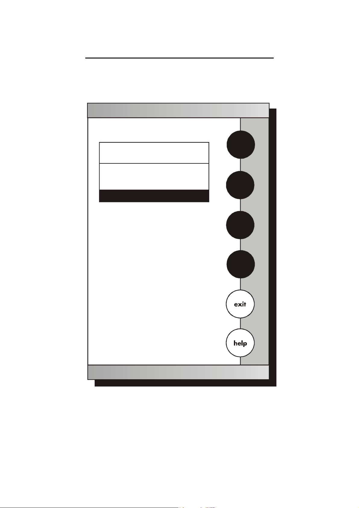
6.14 Set Display Resolution
Set
pH Display Resolution
enter
Current RESOLUTION
X.XX
X.X
Select desired display resolution and then
touch to accept
enter
.XX
.XXX
68
Page 74

Instruction Manual CyberScan PC5500/ 5000
This mode allows you to set the display resolution that you desire on
the screen. You have the choice of one, two or three decimal places.
To Set Display Resolution
1. Access the set display resolution screen from the pH Setup
screen. The current Display Resolution is displayed on the
screen.
2. Touch X.X, X.XX, X.XXX to select the desired resolution of the
display. This will be the format in which your measurement will be
displayed.
3. Touch enter to accept the resolution and return to the pH Setup
screen.
OR
Touch exit to return to the pH Setup screen, without making any
changes.
Example of X.X resolution
pH
channel 1
Example of X.XXX resolution
pH
Example of X.XX resolution
pH
channel 1
channel 1
Remember, HELP is always just a touch of the button away.
69
Page 75

Instruction Manual CyberScan PC5500/ 5000
6.15 Set Display Configuration
Set
pH Display Configuration
Set
mV Display Configuration
Current DISPLAY CONFIGURATION
Current DISPLAY CONFIGURATION
- Last Standardization
- Date
- Time
ON
ON
ON
- Date
- Time
- measurement channel
ON
ON
ON
- measurement channel
- sample ID#
- auto buffer status
- auto read status
- temperature
- slope
- mV Display
ON
ON
ON
ON
ON
ON
ON
- sample ID#
- temperature
ON
ON
Set
Ion Display Configuration
Set
Cond Display Configuration
Current DISPLAY CONFIGURATION
Current DISPLAY CONFIGURATION
- Last Standardization
- Date
- Time
- measurement channel
- sample ID#
- auto read status
- temperature
- slope
- mV Display
- electrode/ method
ON
ON
ON
ON
ON
ON
ON
ON
ON
ON
- Last Standardization
- Date
- Time
- measurement channel
- sample ID#
- Cell Constant
- temperature
- reference temperature
- temperature coefficient
ON
ON
ON
ON
ON
ON
ON
ON
ON
70
Page 76

Instruction Manual CyberScan PC5500/ 5000
This function will allow you to choose what information you would like
to be displayed on the pH Measure screen, particularly the
information contained in the data box at the bottom of that screen.
To Set Display Configuration
1. Access the Set Display Configuration screen from the pH (mV,
Ion, Conductivity) Setup screen. The current display configuration
is displayed on the screen.
2. Use the arrow keys to highlight the Display Configuration criteria
you want to modify.
3. Touch ON or OFF to change the status of the criteria
4. Touch save to save the entire group of display configuration
criteria and return to the pH (mV, Ion, Conductivity) Setup screen.
OR
Touch exit to return to the pH (mV, Ion, Conductivity) Setup
screen, without making any changes.
pH Display Configuration
January 15, 2002 11:11am
ID#
00000
auto buffer
ON
ATC
slope
mV
25.0°C
100%
0000.0
71
Page 77

Instruction Manual CyberScan PC5500/ 5000
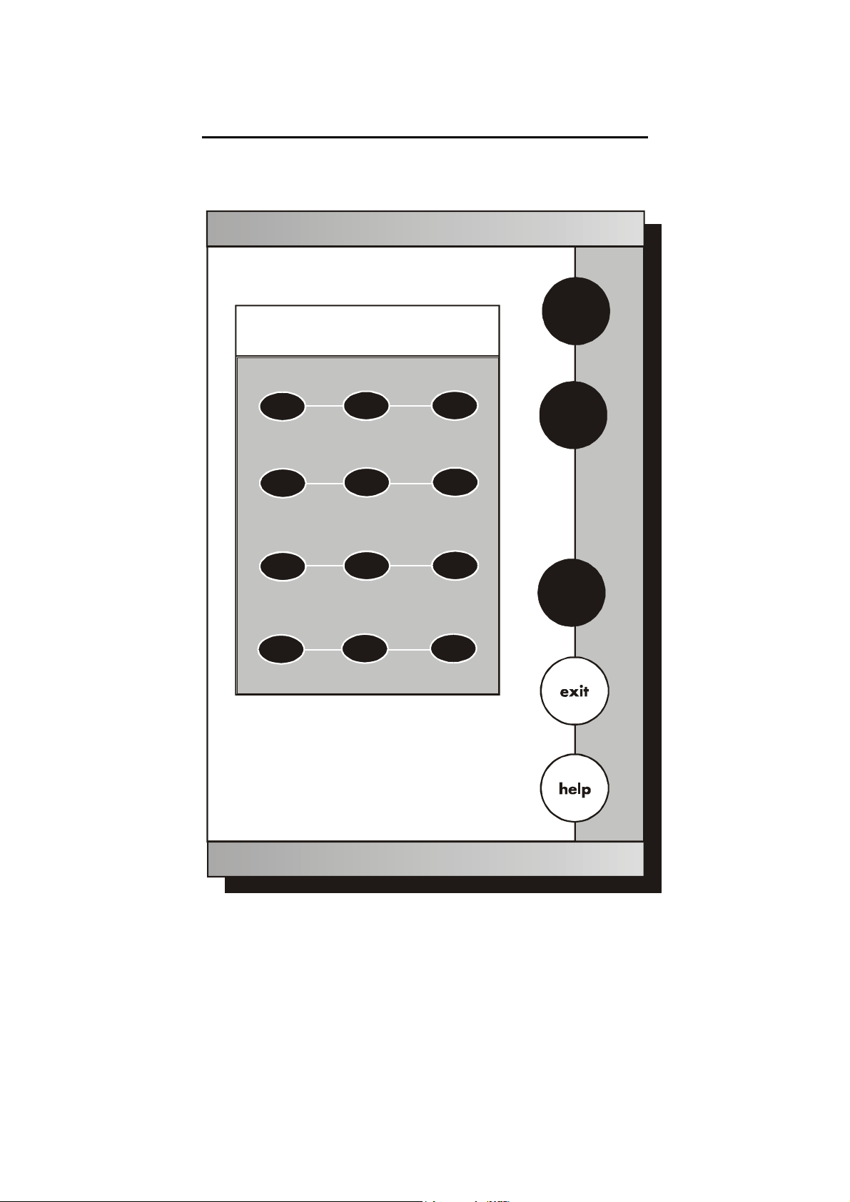
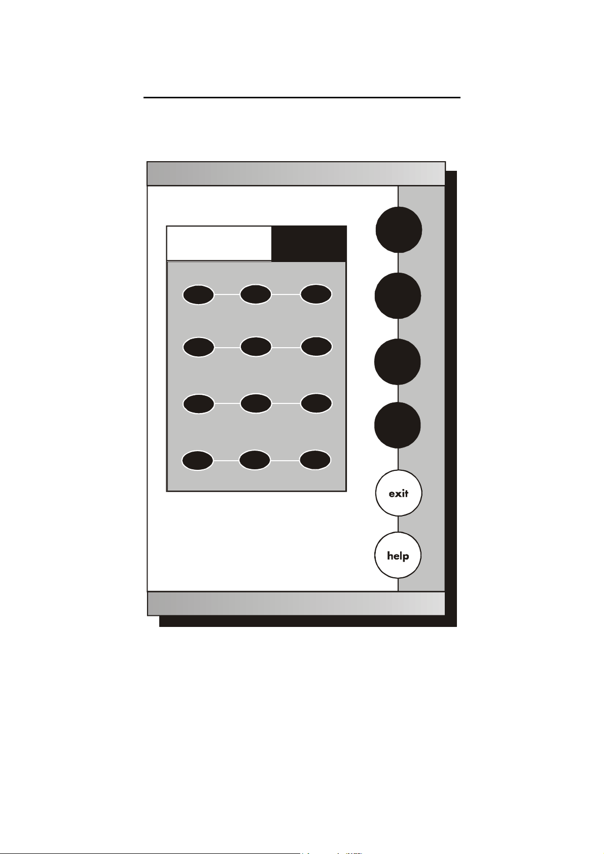
6.16 View Stored Data
View
Stored Data
Data POINTS
Sample ID
Date
Operator
Use to highlight desired sort
arrow keys
option and then touch to accept
enter
17
S
T
enter
72
Page 78

Instruction Manual CyberScan PC5500/ 5000
This meter has memory capacity of up to 250 data points (1000 data
points for PCD5500). The View Stored Data screen allows you to sort
and look at specific data points. The stored data can be sorted by
sample identification number, date or operator identification number.
To View Stored Data
1. Access the view stored data screen from the pH (mV, Ion,
Conductivity) setup screen. The number of data points in the
memory and the sorting options are now displayed on the screen.
2. Use the arrow keys to highlight the desired data sort option.
3. Touch enter to access the sort option screen.
To sort by Sample ID#
1. Access the Sample ID sort option from the View Stored Data
screen.
2. Use the keypad to enter the sample ID# entered in error and reenter the ID#.
3. Touch clear to delete a Sample ID# entered in error and re-enter
the ID#.
4. Touch enter. All data will be sorted by the meter and the first data
point displayed on the screen will be the most recent data point
saved under the selected Sample ID#.
5. Touch next or prev to scroll through additional data points saved
in the memory of the meter.
6. Touch print to send the data to a printer or computer, OR touch
delete to erase the data point from the meter’s memory, OR
touch exit to return to the pH (mV, Ion, Conductivity) Setup
screen.
If a sample ID# is entered and no data points are stored with that
sample ID#, you will see a message indicating the sample ID# was
not found. Touch OK to return to the sample ID# keypad and enter
new sample ID #.
73
Page 79

Instruction Manual CyberScan PC5500/ 5000
To sort by Date
1. Access the Date sort option from the View Stored Data screen.
2. Touch clear to delete the current date.
3. Use the numeric keypad to enter the date on which the data
points you want to view were saved. Be sure to use/ to separate
the month, the day and the year.
4. Touch enter. All data will be sorted by the meter and the first data
point displayed on the screen will be the most recent data point
saved under the selected Date.
5. Touch next or prev to scroll through additional data points saved
in the memory of the meter.
6. Touch print to send the data to a printer, OR touch delete to
erase the data point from the meter’s memory, OR touch exit to
return to the pH (mV, Ion, Conductivity) Setup screen.
7. If a date is entered and no data points are stored with that date,
you will see a message indicating the date was not found. Touch
OK to return to the operator ID keypad and enter a new date.
To sort by Operator
1. Access the Operator sort option from the View sort data screen
2. Use the keypad to enter the Operator ID of the data point(s) that
you want to view.
3. Touch clear to delete an Operator ID entered in error and re-
enter an ID#.
4. Touch enter. All data will be sorted by the meter and the first data
point displayed on the screen will be the most recent data point
saved under the selected Operator ID.
5. Touch next or prev to scroll through additional data points saved
in the memory of the meter.
6. Touch print to send the data to a printer, OR touch delete to
erase the data point from the meter’s memory, OR touch exit to
return to the pH (mV, Ion, Conductivity) Setup screen.
74
Page 80

Instruction Manual CyberScan PC5500/ 5000
If an operator ID is entered and no data points are stored with that
operator ID, you will see a message indicating the operator ID was
not found. Touch OK to return to the operator ID keypad and enter a
new operator ID.
Even if you do not know the appropriate information to access a
specific data point, you can access the stored data through any of the
sort options. Highlight the sort option of interest and touch enter to
access the sort screen. Touch enter again and the meter will place
you at a data point.
• The sample ID# sort option will place you at the first data
point in numeric order by sample ID#.
• The operator sort option will place you at the first data point
of the first operator ID in alphabetic order.
• The date sort option will place you at the most recent point
on the last date that data was stored.
Once you access the data storage center, you can touch prev and
next to scroll through the additional data points stored in memory.
View
Stored Data
Current STORED DATA
January 15, 2002
11:11 am
Channel:
sample ID#:
Ion value:
Ion method:
Ion electrode:
Temp er ature :
Last Std:
Current Stds:
Slope:
mV value:
model#/serial#:
Operator
1
110
1.0
Known Addition
AMMONIA
25.0°C
Jan.15@11:11am
10.0 100
102.2%
0.6
PC5500/ alpha 0001
Tom D.
75
Page 81

Instruction Manual CyberScan PC5500/ 5000
7 mV SETUP
mV Setup (channel 1)
mV SETUP OPTIONS
- Set
Sample ID#
- Set
Alarm Limits
- Set
Print Criteria
- Set
Print Interval
- Set
Data Storage Criteria
- Set
Display Resolution
- Set
Display Configuration
- View
Stored Data
S
T
edit
76
Page 82

Instruction Manual CyberScan PC5500/ 5000
7.1 Access mV Setup
E U T E C H
INSTRUMENTS
pH
Setup
pH
CyberScan PC 5500
Select from the options to the right
Last std: Jan 15 @ 11:11 am
mV Setup (channel 1)
mV SETUP OPTIONS
- Set
Sample ID#
- Set
Alarm Limits
- Set
Print Criteria
- Set
Print Interval
- Set
Data Storage Criteria
- Set
Display Resolution
- Set
Display Configuration
- View
Stored D ata
mV
Ion
Select from the options to the right
Cond Cond
setup
mV
Ion
system
There are two ways to access the mV
S
Setup screen.
From the setup screen
T
1. Touch setup on the main screen.
Touch mV to access the mV Setup
screen.
edit
2. Use the arrow keys to highlight the
setup option that you would like to
review.
3. Touch edit to access the screen
for the selected option.
77
Page 83

Instruction Manual CyberScan PC5500/ 5000
J
E U T E C H
INSTRUMENTS
CyberScan PC 5000
Select from the options to the right
Last std: Jan 15 @ 11:11 am
pH
mV
Ion
setup
From the Setup screen
1. Touch setup on the mV Measure
screen. The mV Setup screen is
now displayed. Touch mV on the
main screen to access the millivolts
mode.
2. Use the arrow keys to highlight the
setup option that you would like to
review.
Measure
abs mV
channel 1
0.0
Tou ch t o me asure s amp le
meas
or
Touch for Relative mV reading
REL
anuary 15, 2002 11:11am
ID#
00000
ATC
mV Setup (channel 1)
mV SETUP OPTIONS
- Set
Sample ID#
- Set
Alarm Limit s
- Set
Print Criteria
- Set
Print Interval
- Set
Data Storage Criteria
- Set
Display Resolution
- Set
Display Configuration
- View
Stored Data
REL
meas
25.0°C
S
T
edit
3. Touch edit to access the screen
for the selected option.
78
Page 84

Instruction Manual CyberScan PC5500/ 5000
To Set Sample ID#
When this option is active, each time you touch print on the Measure
screen the mV value along with the date/time/channel and the sample
ID# will be sent to data storage. You can manually enter an
alphanumeric identification number of up to 9 characters for any
sample, or you can have the meter sequentially number your samples
beginning at the number of your choice. You may also choose to
deactivate the sample ID#.
The mV Sample ID# is set the same way as previously described in
pH setup. See page 49 for instructions.
To Set Alarm Limit
This option allows you to set alarm limits for the mV measuring mode.
If the mV value of the measurement is outside of the boundaries set
by the upper and lower limits, an audible alarm and/ or a visual
warning will appear to let you know that your sample measurement
was outside of the set limits.
The mV alarm limits are set the same way as previously described in
pH setup. See page 64 for instructions.
To Set Print Criteria
This screen allows you to select which criteria are printed with the
measurement when you print the data or send it to the computer. The
status of the current print criteria is displayed on the screen. The
criteria option is active if “ON” appears to the right of the option. It is
inactive if “OFF” appears to the right of the option. Any active criteria
will be printed on demand.
The mV Print Criteria are set the same way as previously described
in pH setup. See page 66 for instructions.
Remember, HELP is always just a touch of the button away.
79
Page 85

Instruction Manual CyberScan PC5500/ 5000
To Set Print Interval
You have three options for setting the print interval: manual printing,
stable reading printing and timed interval printing.
The mV Print Interval is set the same way as previously described in
pH setup. See page 64 for instructions.
To Set Data Storage Criteria
This screen allows you to select what criteria are stored in the meter’s
memory with the measurement when you save the data. The status
of the current data storage criteria is displayed on the screen. The
criteria option Is active if “ON” appears on the right of the screen. It is
inactive is “OFF” appears to the right of the screen. All storage criteria
will stored in the meter’s memory with the measurement. However,
only active items will appear on the View Stored Data screens.
Changing the status of the storage criteria to active from inactive will
allow the criteria to be displayed with the previously stored data.
The mV Data Storage Criteria are set the same way as previously
described in pH Setup. See page 66 for instructions.
To Set Display Configuration
This function will allow you to choose what information you would like
to be displayed on the mV Measure screen, particularly the
information contained in the data box at the bottom of that screen.
The mV display configuration is set the same way as previously
described in pH Setup. See page 70 for instructions.
To View Stored Data
This meter has memory capacity for up to 250 data points (1000 for
PCD5500). The View Stored Data screen allows sorting and looking,
at specific data points. The stored data can be sorted by sample
identification number, date or operator identification number.
The mV stored data is viewed the same way as previously described
in pH setup. See page 72 for instructions.
80
Page 86

Instruction Manual CyberScan PC5500/ 5000
X
7.2 Set Display Resolution
Set
mV Display Resolution
enter
Current RESOLUTION
X.XX
X.X
Select desired display resolution and then
touch to accept
enter
.XX
81
Page 87

Instruction Manual CyberScan PC5500/ 5000
To Set Display Resolution
This mode allows you to set the display resolution that you desire on
the screen. You have the choice of zero or one decimal place.
1. Access the set display resolution screen from the mV setup
screen. The current display resolution is displayed on the screen.
2. Touch X or X.X to select the resolution of the display that you
desire. This will be the format in which your measurement will be
displayed.
3. Touch enter to accept the resolution and return to the mV setup
screen.
OR
Touch exit to return to the mV setup screen, without making any
changes.
Example of X resolution
mV
Example of X.X resolution
mV
channel 1
channel 1
82
Page 88

Instruction Manual CyberScan PC5500/ 5000
8 ION SETUP
Ion Setup (channel 1)
ISE SETUP OPTIONS
- Set
Sample ID#
- Select
- Select
- Select
- Set
- Set
- Set
- Set
- Set
- Set
- Set
- Set
- Set
- View
Ion Method
Measurement Units
Auto Read Mode
Ion Stability Criteria
Default Temperature
Isopotential Point
Alarm Limits
Print Criteria
Print Interval
Data Storage Criteria
Significant Digits
Display Configuration
Stored Data
S
T
edit
The operating parameters of the ion mode can be set and controlled
from the Ion Setup screen. The following sections will guide you
through the various options available for the ion setup mode.
83
Page 89

Instruction Manual CyberScan PC5500/ 5000
8.1 Access Ion Setup
E U T E C H
INSTRUMENTS
Select from the options to the right
Ion Setup (channel 1)
ISE SETUP OPTIONS
- Set
Sample ID
- Select
Ion Method
- Select
Measurement Units
- Set
Auto Read Mode
- Set
Ion St ability Criteria
- Set
Default Temperature
- Set
Electrode Type
- Set
Isopotential Point
- Set
Alarm Limits
- Set
Print Criteria
- Set
Print Interval
- Set
Data Storage Criteria
- Set
Significant Dig its
- Set
Display Configuration
- View
Stored Data
pH
mV
Ion
Cond
setup
Setup
Select from the options to the right
pH
mV
Ion
Cond
system
There are two ways to access the Ion
S
Setup screen
From the Setup screen
T
1. Touch setup on the main screen.
Then touch Ion on the Ion Setup
screen.
edit
2. Use the arrow keys to highlight the
setup option that you would like to
review.
3. Touch edit to access the screen
for the selected option.
84
Page 90

Instruction Manual CyberScan PC5500/ 5000
E U T E C H
INSTRUMENTS
CyberScan PC 5000
Select from the options to the right
Last std: Jan 15 @ 11:11 am
pH
mV
Ion
Cond
setup
From the Ion Measure screen
4. Touch Ion on the main screen
to access the Ion mode. Touch
setup on the Ion Measure
screen. The Ion Setup screen
is now displayed.
5. Use the arrow keys to
highlight the setup option that
you would like to review.
6. Touch edit to access the
screen for the selected option.
Measure
ppm
channel 1
0.0
STANDARDS
Ion Setup
- Set
- Sele ct
- Selec t
- Selec t
- Set
Set
-
- Set
- Set
- Set
- Set
- Set
- Set
- Set
- Set
- View
Last st d: Jan 15 @ 11:11 am
Touch to access stand ardize mode
std
January 15, 2002 11:11am
ID#
00000
Nh3
ISE SETUP OPTIONS
Sample ID#
Ion Method
Measurement Units
Auto Read Mode
pH Stability Criteria
Default Temperature
Electrode Type
Isopotentia l Point
Alarm Limi ts
Print Criteria
Print In terval
Data Storage Crit eria
Significant Digits
Display Configuration
Stored Data
ATC
Slope
NA
mV
0000.0
std
meas
setup
25.0°C
S
T
edit
85
Page 91

Instruction Manual CyberScan PC5500/ 5000
8.2 Select Ion Method
To Set Sample ID#
When this option is active, each time you touch print on the Measure
screen the ion concentration value along with date/ time/ channel and
the sample ID# will be sent to data storage. You can manually enter
an alphanumeric identification number of up to 9 characters for any
sample or you can have the meter sequentially number your samples
beginning at the number of your choice. You may also choose to
deactivate the sample ID#.
The ion sample ID# is set the same way as previously described in
pH Setup. See page 44 for instructions.
To Select Ion Method
1. Use the arrow keys to highlight the method you want to use.
2. Touch enter to accept the method and return to the Setup
screen.
OR
Touch exit to return to the Ion setup screen, without making any
changes.
Select
Ion Method
Current METHOD
Direct Reading with Standards
Direct Read with Blank offset
Known Addition
Known Subtraction
Analate Addition
Analate Subtraction
Blank
S
T
enter
86
Page 92

Instruction Manual CyberScan PC5500/ 5000
Direct Reading with Standards
The direct reading method is the most common method of ion
measurement. When using this method, you will use standards of
known values to standardize the meter with ion standards. An ionic
strength adjuster (ISA) is added to both the standards and the
sample. 2 to 5 standards are used to standardize the meter. The
standards should bracket the expected value of the sample. The Ion
specific electrode is immersed in a stirring sample and the ion
concentration is read directly from the meter.
Direct Reading with Blank offset
The blank method is a method commonly used for determination of
ion concentration in a sample with a very low level of ions present.
Because of background interference at low concentration levels, a
blank is used and the value of the ion concentration in the blank is
subtracted from the value of the measured sample.
Known Addition Method
The known addition method is an incremental method used for
samples with a complex matrix. A standard with a known
concentration of the ion species of interest is added to the sample.
The difference in mV potential is then used to calculate the
concentration of the ion of interest.
Known Subtraction Method
The known subtraction method is also an incremental method. The
ion of interest in the sample is not identical to the ion in the standard
solution. The standard of known ion concentration that is added to the
sample quantitatively reacts in the sample with the ion of interest.
This reaction removes a fixed amount of the ion of interest from the
sample solution. The ion concentration is then calculated based upon
the difference in the mV potential.
Analate addition
The analate addition method is a modification of the known addition
method. In the Analate Addition method, the initial mV measurement
is recorded in a standard solution. The ion in the standard solution is
the ion of interest and is detected by the ion selective electrode in
use. A sample containing the ion of interest is then added to the
standard solution. The difference in the mV potential is then used in
the calculation of the concentration of the ion of interest. This method
is useful if the sample temperature is significantly different than that
of the standard. When the small volume of hot sample is added to the
larger volume, the temperature impact becomes negligible.
87
Page 93

Instruction Manual CyberScan PC5500/ 5000
Analate Subtraction
The analate subtraction method is particularly useful in the event that
there is no ion specific electrode available to directly measure the
concentration of the ion of interest. This method employs the addition
of a sample of the ion of interest to a standard containing a different
ion of known concentration. The ion of interest will quantitatively react
with the ion in the standard, creating a complex and removing the ion
from the standard solution. The ion specific electrode is specific for
the ion in the standard solution and not for the ion of interest. The
difference in mV potential is used to calculate the concentration of the
ion of interest based upon this quantitative reaction.
8.3 Select Measurement Units
This screen allows you to select the units in which the meter will
report the concentration of the ion of interest. The current units are
displayed on the screen.
To Select Measurement Units
1. Access the Select Measurement Units screen from the Ion Setup
screen. The current units are displayed on the screen.
2. Use the arrow keys to highlight the desired units.
3. Touch enter to accept these units and return to the Ion Setup
screen.
OR
Touch exit to return to the ion setup screen, without making any
changes
Select Ion
Measurement Units
S
Current UNITS
ppm
mg/ml
mg/L
mole/L
Percent
mg/ml
T
enter
88
Page 94

Instruction Manual CyberScan PC5500/ 5000
To Select Auto Read Mode
You can use this meter when the Auto Read Mode function is active
or when it is inactive. When the Auto Read function is active, the
meter will lock onto a reading when the meter recognises it as stable.
The meter will not deviate from this reading until meas is touched. If
the auto Read function is inactive, then the meter will continuously
monitor the concentration of the ion of interest. The display on the
measure screen display will indicate any fluctuation in the ion
concentration.
To Set Ion Stability Criteria
The setup screen allows you to determine how quickly the meter will
respond to electrode drift. There are 3 speed settings.
The Ion Stability Criteria is set the same way as previously described
in pH Setup.
To Set Default Temperature
Ion concentration is a temperature dependent measurement. The
default temperature option allows you to select the temperature that
will be used by the meter to calculate the correct ion concentration.
The factory default setting is 25°C. You should enter the temperature
value of that solution as the default temperature in order to get the
correct concentration value. The current default temperature setting
will be displayed when the Set Default Temperature screen is
displayed.
The Ion Default Temperature is set the same way as previously
described in pH setup. See page 56 for instructions.
Regardless of the status of the Auto Read Mode, STABLE will be
displayed as the meter recognises the measurement as stable.
Stability criteria are more stringent at the slower setting. Therefore, if
the highest precision is required, then a slow setting would be
desired. The medium or slow setting is recommended for Ion work.
Best results are obtained when the standards and the samples are at
the same temperature.
89
Page 95

Instruction Manual CyberScan PC5500/ 5000
8.4 Select Electrode Type
This screen allows you to select the type of electrode that is specific
for your ion of interest. Your choice of electrode informs the meter
which default slope to use in the calculations made for the electrode
efficiency and sample concentration. Once you have selected an
electrode, you will not be required to enter the default slope
numerically.
Note:
The default slope value specific for the electrode that you choose is a
theoretical slope value that is used in the calculations to determine
the efficiency of your electrode. This slope value is not the slope
value that is displayed in the data box of the measurement screen.
You will still need to standardize the meter using ion standards to
determine the actual efficiency of your electrode.
To Select Electrode Type
1. Access the Select Electrode Type screen from the Ion Setup
screen. The current units are displayed on the screen.
2. Use the arrow keys to highlight the desired units.
3. Touch enter to accept Electrode Type and return to the Ion Setup
screen.
OR
Touch exit to return to the ion setup screen, without making any
changes
90
Page 96

Instruction Manual CyberScan PC5500/ 5000
To Set Isopotential point
The Isopotential point is the millivolts reading for an electrode at
which temperature has no effect on the measurement. Ion selective
electrodes, unlike pH electrodes, are not designed to achieve any
particular isopotential point. If samples and standards are at different
temperatures when performing ISE experiments, it will be necessary
to experimentally determine the isopotential point of your own Ion
Specific Electrode.
The Ion Isopotential Point is set the same way as previously
described in pH setup. See page 58 for instructions.
To Set Alarm Limits
This option allows you to set alarm limits for the Ion measuring mode.
If the ion concentration measurement is outside the boundaries set by
the minimum and maximum limits, an audible alarm and/ or a visual
warning will appear to let you know that your sample measurement
was outside of the set limits.
The Ion Alarm Limits is set the same way as previously described in
pH setup. See page 60 for instructions.
To Set Print Criteria
This screen allows you to select which criteria are printed with the
measurement when you print the data or send it to the computer. The
status of the current print criteria is displayed on the screen. The
criteria option is active if “ON” appears to the right of the option. It is
inactive if “OFF” appears to the right of the option. Any active criteria
will be printed on demand.
The Ion Print Criteria are set the same way as previously described in
pH setup. See page 62 for instructions.
To Set Print Interval
You have three options for setting the print interval: manual printing,
stable reading printing and timed interval printing.
The Ion Print Interval is set the same way as previously described in
pH setup. See page 64 for instructions.
To Set Data Storage Criteria
This screen allows you to select what criteria are stored in the meter’s
memory with the measurement when you save the data. The status
of the current data storage criteria is displayed on the screen. The
criteria option is active if “ON” appears to the right on the screen. It is
inactive if “OFF” appears to the right of the option. Any active criteria
will be stored with the measurement. All storage criteria will be stored
in the meter’s memory with the measurement. However, only active
items will appear on the View Stored Data screens. Changing the
status of the storage criteria to active from inactive will allow the
criteria to be displayed with the previously stored data.
The Ion Data Storage Criteria is set the same way as previously
described in pH setup. See page 66 for instructions.
91
Page 97

Instruction Manual CyberScan PC5500/ 5000
8.5 Set Significant Digits
Set
Ion Significant Digits
enter
Current SIG DIGITS
2
2423
Select desired significant digits and then
enter
touch to accept
Example of 1 significant digit
ppm
channel 1
Example of 3 signific ant digits
ppm
Example of 2 significant digits
ppm
channel 1
channel 1
92
Page 98

Instruction Manual CyberScan PC5500/ 5000
This option allows you to select the number of significant figures that
will be used when reporting your ion measurement. You have the
choice of one, two or three significant digits.
To Set Significant Digits
1. Access the Set Significant Digits screen from the Ion Setup
screen. The current Significant Digits is displayed on the screen.
2. Touch 1, 2 or 3 to select the desired significant digits.
3. Touch enter to accept the number of significant digits and return
to the Ion Setup screen.
OR
Touch exit to return to the Ion Setup screen, without making any
changes.
To Set Display Configuration
This function will allow you to choose what information you would like
to be displayed on the Ion Measure Screen, particularly the
information contained in the data box at the bottom of that screen.
The Ion Display Configuration is set the same way as previously
described in pH setup.
To View Stored Data
This meter has memory capacity for up to 250 data points (1000 for
PCD5500). The View Stored Data screen allows you to sort and look
at specific data points. The stored data can be sorted by sample
identification number, data or operator identification number.
The Ion Stored Data is set the same way as previously described in
pH setup.
93
Page 99

Instruction Manual CyberScan PC5500/ 5000
9 CONDUCTIVITY SETUP
The operating parameters of the conductivity mode can be set and
controlled from the Conductivity Setup screen. The following sections
will guide you through the various options available for the
conductivity setup mode.
Conductivity Setup (channel 1)
CONDUCTIVITY SETUP OPTIONS
- Set
Sample ID
- Select
- Select
- Set
- Set
- Set
- Perform
- Set
- Set
- Set
- Set
- Set
- Set
- View
Conductivity Units
Cell Constant
Default Temperature
Reference Temperature
Temperature Coefficient
Replatinize
Alarm Limits
Print Criteria
Print Interval
Data Storage Criteria
Significant Digits
Display Configuration
Stored Data
S
T
edit
94
Page 100

Instruction Manual CyberScan PC5500/ 5000
9.1 Access the Conductivity Setup
E U T E C H
INSTRUMENTS
pH
Setup
pH
CyberScan PC 5000
mV
mV
Select from the options to the right
Last std: Jan 15 @ 11:11 am
Conductivity Setup (channel 1)
CONDUCTIVITY SETUP OPTIONS
- Set
Sample ID
- Select
Conductivity Units
- Select
Cell Constant
- Set
Default Temperature
- Set
Reference Temperature
- Set
Temperature Coefficient
- Perform
Replatinize
- Set
Alarm Limits
- Set
Print Criteria
- Set
Print Interval
- Set
Data Storage Criteria
- Set
Significant Digits
- Set
Display C onfiguration
- View
Stored Data
Ion
Cond
setup
S
T
edit
Ion
Select from the options to the right
Cond
system
There are two ways to access the
Conductivity Setup screen.
From the Setup screen
1. Touch setup on the main
screen. Then touch Cond to
access the conductivity Setup
screen.
2. Use the arrow keys to highlight
the setup option that you would
like to review.
3. Touch edit to access the screen
for the selected option.
95
 Loading...