

Page 1
gyM
y..
.
Instruction Manual
PC 10
Waterproof Hand-held pH/Conductivity/Temperature Meter
68X230401
Technol o
adeEas
Rev 5 08/04
Page 2

Page 3

Preface
This manual serves to explain the use of the Waterproof PC 10 hand-held meters. It functions
as a step by step guide to help you operate the meter and as a handy reference guide. It is
written to cover as many anticipated applications of the Waterproof PC 10 meters as possible.
If there are doubts in the use of this meter, please do not hesitate to contact the nearest
Authorised Distributor.
Eutech Instruments/ Oakton Instruments cannot accept any responsibility for damage or
malfunction to the meter caused by improper use of the instrument.
The information presented in this manual is subject to change without notice as improvements
are made, and does not represent a commitment on the part of Eutech Instruments Pte Ltd/
Oakton Instruments.
Copyright © 1999
Eutech Instruments Pte Ltd/ Oakton Instruments
All rights reserved.
Rev 5, 08/04
Page 4

TABLE OF CONTENTS
1.
INTRODUCTION........................................................................................1
2. DISPLAY AND KEYPAD FUNCTIONS...................................................2
2.1. DISPLAY.................................................................................................2
2.2. KEYPAD .................................................................................................3
3. PREPARATION...........................................................................................4
3.1 INSERTING THE BATTERIES ....................................................................4
3.2 CONNECTING THE PROBE.......................................................................5
4. CALIBRATION............................................................................................6
4.1. IMPORTANT INFORMATION ON METER CALIBRATION............................6
4.2. PREPARING THE METER FOR CALIBRATION ...........................................7
4.3. TEMPERATURE CALIBRATION ................................................................8
4.4. PH CALIBRATION .................................................................................10
NOTES..................................................................................................................11
4.5. CONDUCTIVITY CALIBRATION .............................................................12
4.6. CALIBRATING FOR CONDUCTIVITY: .....................................................13
NOTES:.................................................................................................................14
5. MEASUREMENT......................................................................................15
6. HOLD FUNCTION....................................................................................16
7. PROBE CARE AND MAINTENANCE...................................................17
8. TROUBLESHOOTING.............................................................................18
9. ERROR MESSAGES.................................................................................19
10. SPECIFICATIONS................................................................................20
11. ACCESSORIES.....................................................................................21
11.1. REPLACEMENT METER AND METER ACCESSORIES...............................21
11.2. CALIBRATION SOLUTIONS....................................................................23
12. WARRANTY..........................................................................................24
13. RETURN OF ITEMS............................................................................25
Page 5
Instruction Manual PC 10
1. INTRODUCTION
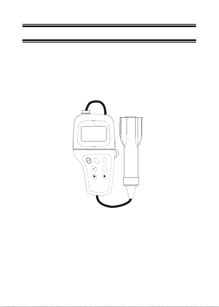
Thank you for selecting the Waterproof PC 10 portable meter. The meter is a microprocessor-
based instrument that measures pH, conductivity, and temperature with just one probe. This
meter has many user-friendly features – all of which are completely accessible through the
water-resistant membrane keypad.
Your meter includes 4 “AAA” batteries and a combination pH / conductivity / temperature
probe with 3-meter submersible cable. Please read this manual thoroughly before operating
your meter.
WATERPROOF
pH/ Conductivity/ °C Meter
PC 10 Series
N
O
F
F
O
E
D
L
D
O
O
H
M
L
A
R
C
E
T
S
N
A
E
E
M
Figure 1: Waterproof PC 10 portable meter
- 1 -
Page 6
Instruction Manual PC 10
2. DISPLAY AND KEYPAD FUNCTIONS
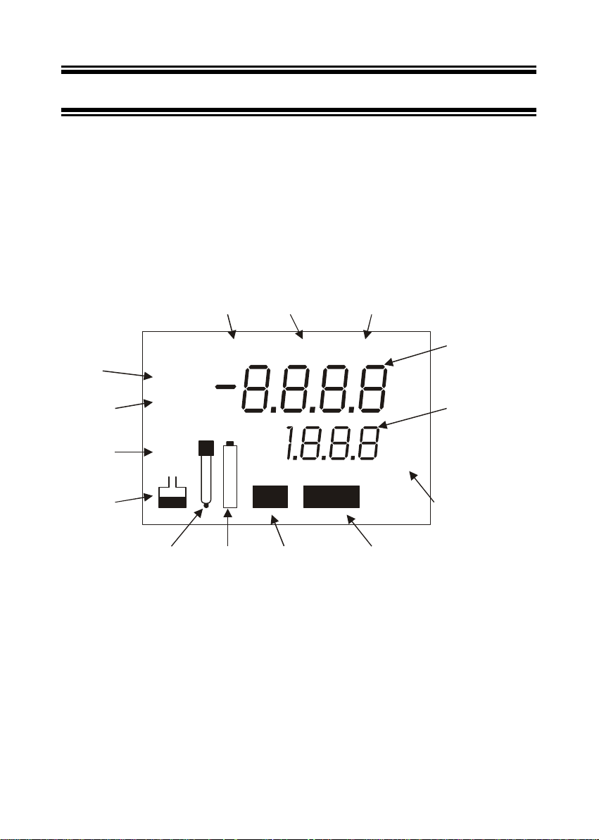
2.1. Display
The LCD has a primary and secondary display.
• The primary display shows the measured pH or conductivity (µS or mS)
reading.
• The secondary display shows the temperature in °C.
The display also shows error messages, keypad functions and program functions.
See Figure 2.
READY
indicator
HOLD
indicator
MEASurement
mode indicator
READY
HOLD
CALibr ation
indicator
CONfirm
indicator
CONMEAS CAL
pH
µ
mS
Primary
Display
Secondary
Display
pH
ERRor
indicator
Buffer
indicator
ERR
pH Temp
°C
ATC
Autom atic
Temperature
Compensation
indicator
Probe
indicator
Low Battery
indicator
pH calibration
mode indicator
Figure 2: A full LCD screen
- 2 -
Temperature
calibration
mode indicator
Page 7
Instruction Manual PC 10
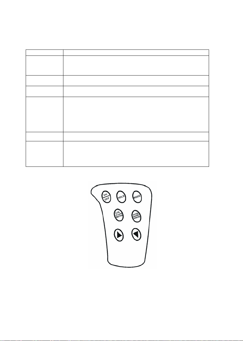
2.2. Keypad
The large membrane keypad makes the instrument easy to use. Each button, when pressed,
has a corresponding graphic indicator on the LCD. See Figure 3.
Key Function
ON/OFF Powers on and shuts off the meter. The meter powers on in the mode it was
HOLD Freezes the measured reading. To activate, press HOLD while in
MODE Selects the measurement parameter (conductivity or pH). Press MODE to
CAL/MEAS Toggles user between Calibration and Measurement mode.
ENTER Press to confirm your calibration values in Calibration mode.
/ Scrolls values up and down in Calibration mode.
shut off in. For example, if you shut the meter off in Conductivity measurement
mode, the meter will be in Conductivity measurement mode when you switch
the meter on.
measurement mode. To release, press HOLD again.
toggle between pH and Conductivity mode.
If you were in Conductivity Measurement mode, press CAL/MEAS to enter
Conductivity Calibration mode.
If you were in pH Measurement mode, press CAL/MEAS to enter pH
Calibration mode.
NOTE: Temperature calibration is accessible from pH Calibration mode; see
pages 10 for instructions.
In pH mode, / scrolls through the auto buffer values 4.00, 7.00 and
10.00.
In Conductivity and Temperature Calibration mode, / lets you increase
or decrease the calibration value.
Figure 3: Keypad membranes of Water proof PC 10
- 3 -
Page 8
Instruction Manual PC 10
3. PREPARATION
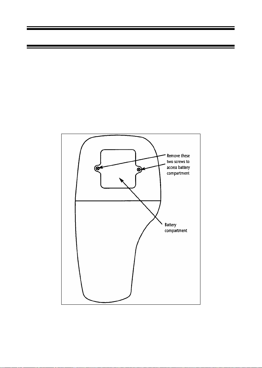
3.1 Inserting the Batteries
The meter is packaged with 4 “AAA” alkaline batteries required for operation. To insert the
batteries into the meter, follow the procedure outlined below.
1. Use a Philips screwdriver to remove the two screws holding the battery cover. See Figure
6 below.
2. Remove battery cover.
3. Insert batteries. Follow the diagram inside the cover for correct polarity.
4. Replace the battery cover into its original position using the two screws removed earlier.
Figure 4: Battery Compartment
- 4 -
Page 9
Instruction Manual PC 10
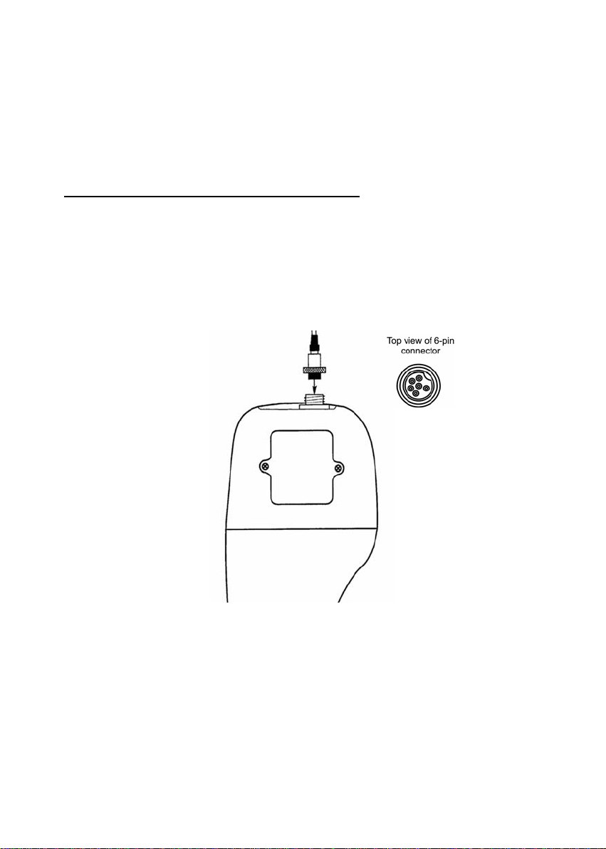
3.2 Connecting the Probe
The Waterproof PC 10 meter uses a special combination pH / Conductivity / Temperature
probe. The probe cable has a notched 6-pin connector to attach the probe to the meter.
NOTE: Do not substitute other probes or electrodes. For replacement probe, see
the “Accessories” section, page 21-23.
NOTE: Keep connector dry and clean. Do not touch connector with soiled hands.
To connect the pH / Conductivity / Temperature probe:
1. Line up the notch and 6 pins of the meter’s connector with the holes in the probe’s
connector. Push down and screw the metal sleeve to lock the probe connector into
place. See Figure 5.
2. To remove probe, unscrew the metal sleeve and slide up the probe connector. While
holding onto metal sleeve, pull probe away from the meter.
CAUTION: Do not pull on the probe cord or the probe wires might disconnect.
Figure 5: Probe Connector
- 5 -
Page 10
Instruction Manual PC 10
4. CALIBRATION
4.1. Important Information on Meter Calibration
When you recalibrate your meter, old pH and conductivity calibration data are replaced on a
point by point basis. For example, if you previously calibrated your meter at pH 4.0, 7.0, and
10.0, and you recalibrate at pH 7.0, the meter retains the old calibration data at pH 4.0 and pH
10.0.
To completely recalibrate your meter, or when you use a replacement probe, it is best to set
the meter to its factory defaults and recalibrate the meter at all points.
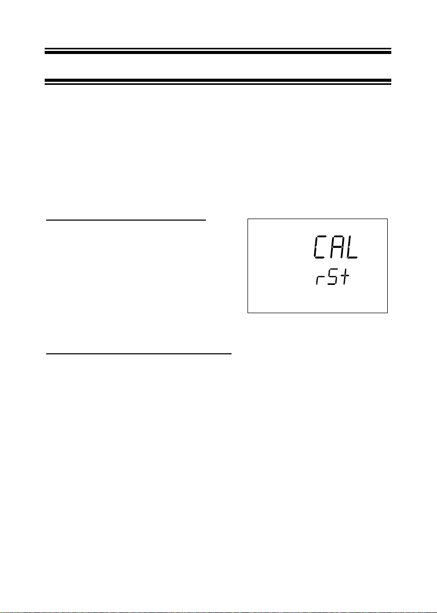
To reset the meter to its factory defaults:
1. While in Measurement mode, press
CAL/MEAS and hold for 3 seconds.
2. The meter will prompt RST in the lower display
and CAL in the upper display. See Figure 6.
3. Press ENTER to reset your meter to its factory
defaults. If you do not want to erase existing
calibration data, press CAL/MEAS to escape
this mode.
For information on how to calibrate your meter:
See Section 4.3 on page 8 for Temperature calibration.
See Section 4.4 on pages 10 for pH calibration.
See Section 4.5 on pages 12 for conductivity calibration.
Figure 6: Reset to factory defaults
- 6 -
Page 11
Instruction Manual PC 10
y
4.2. Preparing the Meter for Calibration
The pH/conductivity/temperature probe included with this meter is designed for use with this
meter only. Do not substitute other types of probes or electrodes. For a replacement probe,
see the “Accessories” section, page 21.
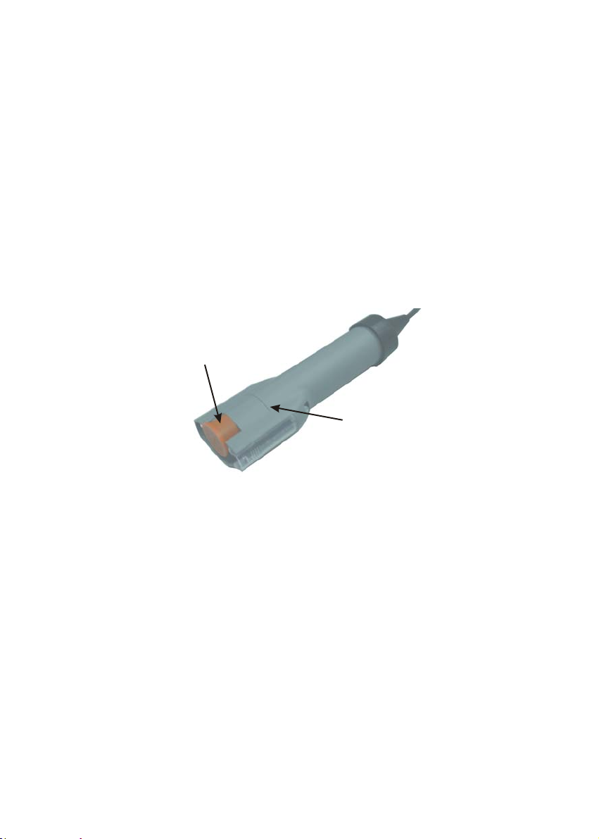
Be sure to remove the protective cap of the pH probe before calibration or
measurement. Always immerse the probe beyond the electrode band.
Immerse the probe in tap water for 10 minutes before calibrating or taking readings to hydrate
the pH electrode surface and minimise drift.
Rinse your probe in DI water after use. Storage in electrode storage solution is ideal.
Alternatively, pH 4.0 or 7.0 calibration standards can be used for short term storage. Do not
reuse buffer solutions after calibration. Contaminants in the solution can affect the calibration,
and eventually the accuracy of the measurements.
Always remove this protective cap
before calibration or measurement
Always immerse the
electrode be
ond this band
- 7 -
Page 12

Instruction Manual PC 10
4.3. Temperature Calibration
The built-in temperature sensor included in the
probe is factory calibrated. Calibrate your sensor
only if you suspect temperature errors may have
occurred over a long period of time or if you have a
replacement probe.
1. Turn the meter on. Press MODE to select pH
Measurement mode.
2. Press the CAL/MEAS key to enter pH
calibration mode. The CAL indicator will appear
above the primary display.
See Figure 10.
3. While in pH calibration mode, press the MODE
key to enter temperature calibration mode. The
primary display shows the temperature reading
with zero offset and the secondary display
shows you what the temperature value was
initially.
See Figure 11.
4. Dip the probe into a solution with known
temperature (i.e. a temperature bath). Allow
sufficient time for the meter’s temperature
reading to stabilize.
5. Press the or key to set the primary display
reading to the correct temperature value. (i.e.
the temperature of the temperature bath)
See Figure 12.
Figure 7: Enter pH Calibration mode
Figure 8: Initial temperature value
Figure 9: Adjust temperature value
- 8 -
Page 13

Instruction Manual PC 10
6. Press the ENTER key to confirm temperature
calibration. The CON indicator will flash to
confirm calibration.
See Figure 13.
NOTES
To exit from Temperature Calibration mode without
confirming calibration, DO NOT press ENTER in step
6. Press CAL/MEAS instead.
Temperature calibration is restricted to ±5°C from
Figure 10: CONFIRM temperature
calibration
the initial value displayed during calibration (shown
in the secondary display).
Since temperature readings affect the accuracy of the pH and conductivity measurements, it is
strongly recommended to carry out pH and conductivity calibration after a temperature
calibration is done.
- 9 -
Page 14

Instruction Manual PC 10
g
4.4. pH Calibration
This instrument is capable of up to 3-point pH calibration to ensure accuracy across the entire
pH range of the meter. You can perform 1, 2, or 3 point calibration with standard pH buffers of
4.01, 7.00 and 10.00.
We recommend that you perform at least 2-point calibration using standard buffers that covers
the expected sample range. You can also perform a 1-point calibration, but make sure that the
buffer value is close to the sample value you are measuring.
This meter features three pre-programmed pH buffers (pH 4.01, 7.00 and 10.00). The meter
automatically recognizes and calibrates to these standard buffer values, which makes pH
calibration faster and easier.
Calibrating for pH:
1. If necessary, press the MODE key to select pH mode. The pH indicator appears in the
upper right hand corner of the display.
2. Rinse the probe thoroughly with DI water or a rinse solution. Do not wipe the probe; this
causes a build-up of electrostatic charge on the
glass surface.
3. Dip the probe into the calibration buffer. The
end of the probe must be completely immersed
into the sample. Stir the sample using the
probe gently to create a homogeneous sample.
4. Press CAL/MEAS to enter pH calibration mode.
The primary display will show the measured
reading while the smaller secondary display will
indicate the pH standard buffer solution.
See Figure 11.
NOTE: If using a pH buffer other than pH 7,
5. Wait for the measured pH value to stabilize.
The READY indicator will display when the
reading stabilizes.
See Figure 12.
press the
or key to scroll up or
down until the secondary display value
is the same as your pH buffer value
(pH 4.00, 7.00 or 10.00).
Figure 11: Calibration at pH 7. 00
Figure 12: READY is displayed when
readin
is stable
- 10 -
Page 15

Instruction Manual PC 10
6. After the reading has stabilized and the READY
indicator is displayed, press ENTER to confirm
calibration. A confirming indicator (CON)
flashes and disappears. The meter is now
calibrated to the buffer indicated in the
secondary display.
See Figure 13.
The secondary display automatically scrolls to the
next buffer calibration option.
If you are performing multi-point calibration, go to
Figure 13: CONFIRM calibration point
step 7.
If you are performing one-point calibration, go to step
10.
7. Press the or key to select the next buffer value you want to calibrate (pH 4.00, 7.00
or 10.00).
See Figure 14.
8. Rinse the probe with DI water or a rinse
solution, and place it in the next pH buffer you
want to calibrate.
9. Follow steps 5 to 8 for all calibration processes
(up to 3 points).
10. When calibration is complete, press
CAL/MEAS to return to pH measurement
Figure 14: Next calibration point
mode.
NOTES
To exit from pH Calibration mode without confirming calibration, DO NOT press ENTER in
step 6. Press CAL/MEAS instead.
If the selected buffer value is not within ±1.00 pH from the measured pH value:
The electrode and buffer icon blink and the ERR annunciator appears in the lower left corner
of the display. These indicators also flash if the buffer used is not the same as the buffer value
on the secondary display.
- 11 -
Page 16

Instruction Manual PC 10
4.5. Conductivity Calibration
The Important Information on Conductivity Calibration
Your meter has four measuring ranges. You can calibrate one point in each of the measuring
ranges (up to four points). If you are measuring values in more than one range, make sure to
calibrate each of the ranges you are measuring.
The following table lists the corresponding conductivity range. You should calibrate each
range using a solution that falls between the values in the “recommended calibration solution
range” column.
Conductivity Range Recommended Calibration
Solution Range
0.00 to 19.99 µS 6.00 to 17.00 µS
0.0 to 199.9 µS 60.0 to 170.0 µS
0 to 1999 µS 600 to 1700 µS
0.00 to 19.99 mS 6.00 to 17.00 mS
NOTE:
Minimum calibration value should be 20% of full scale for the specific range. E.g.: The
LOWEST calibration value for the range of 0.00 to 19.99 µS is 4.00 µS.
When you recalibrate your meter, old calibrations are replaced on a range basis. For example,
if you previously calibrated your conductivity meter at 1413 µS in the 0 to 1999 µS range and
you recalibrate at 1500 µS (also in the 0 to 1999 µS range), the meter will replace the old
calibration data (1413 µS) in that range. The meter will retain all calibration data in other
ranges.
To completely recalibrate your meter, or when you use a replacement probe, it is best to clear
all calibration data in memory. To erase all the old conductivity data, see Section 4.1:
Important Information on Meter Calibration.
NOTE:
These meters are factory set to a temperature coefficient of 2.00% per °C. For most
applications this will provide good results. The factory default value for normalization
temperature is 25°C.
- 12 -
Page 17
Instruction Manual PC 10
4.6. Calibrating for Conductivity:
1. Pour out two separate portions of your calibration
standard and one of DI water into separate clean
containers.
2. If necessary, press MODE key to select
Conductivity Mode. The µS and mS indicator will
appear on the right side of the display.
3. Rinse your probe with DI water, then rinse the
probe in one portion of the calibration standard.
Immerse the probe into the second portion of the
calibration standard. The meter auto ranging
function selects the appropriate conductivity range
(four ranges are possible). Be sure the probe is
free from air bubbles and sufficient calibration
standard is used to cover the conductivity sensor.
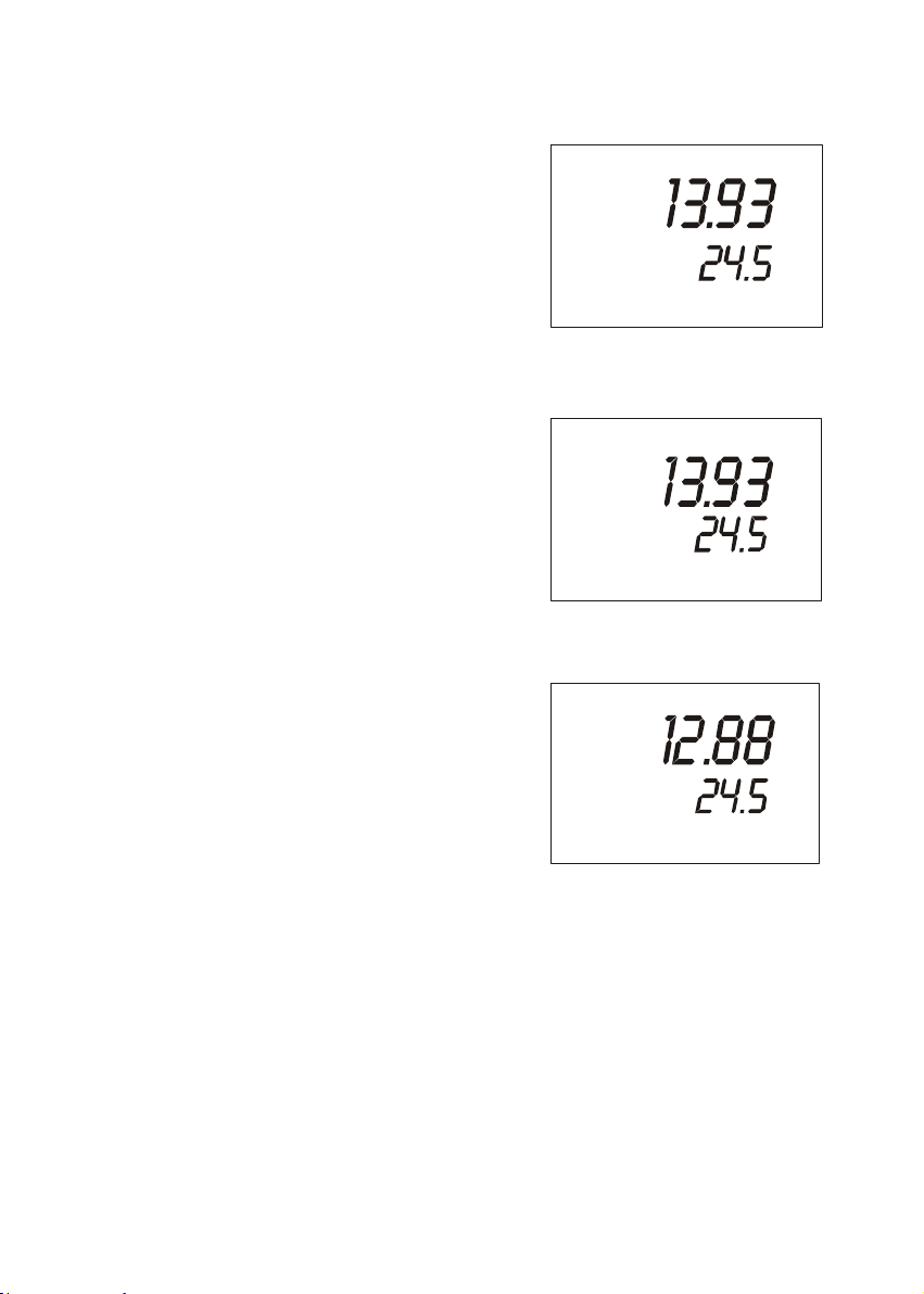
Wait for the reading to stabilize. The READY
indicator lights when the reading is stable.
See Figure 18
4. Press the CAL/MEAS key. The CAL indicator
appears above the primary display. The primary
display shows the measured reading and the
secondary display shows the temperature.
See Figure 19.
5. Press the ▼ or ▲ key to scroll to the value of your
conductivity standard. Press and hold the ▼ or ▲
keys to scroll faster. See Figure 20.
MEAS
READY
Figure 15: Stabilized measurement
CAL
READY
Figure 16: CAL Indicator
CAL
READY
mS
°C
ATC
mS
°C
ATC
mS
°C
ATC
- 13 -
Figure 17: Adjust to standard value
Page 18
Instruction Manual PC 10
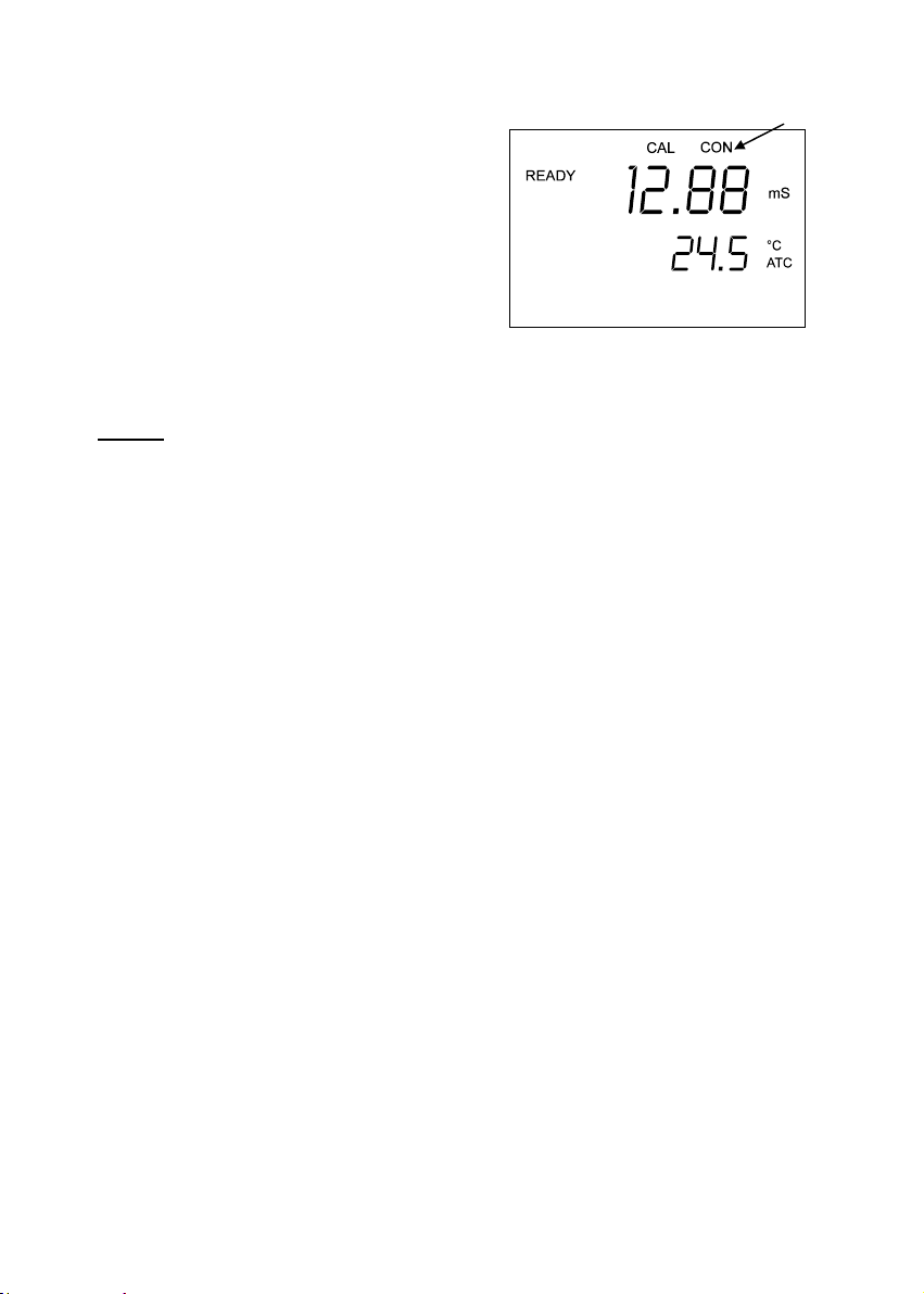
6. Press the ENTER key to confirm calibration.
Upon confirmation, the CON indicator
appears briefly. The meter automatically
switches back into Measurement mode. The
display now shows the calibrated,
temperature compensated conductivity value.
See Figure 21.
7. For calibration in other ranges (maximum:
four ranges) repeat steps 1 through 6 with
the appropriate calibration standards.
Figure 18 CONFIRM the calibration value
NOTES:
To exit from Conductivity Calibration mode without confirming calibration, DO NOT press
ENTER in step 6. Press CAL/MEAS instead.
If the calibration value input into the meter is different from the initial value displayed by more
than 20%, the ERR annunciator appears in the lower left corner of the display.
- 14 -
Page 19

Instruction Manual PC 10
5. MEASUREMENT
The READY indicator appears on the display when
the readings stabilise. It will turn off if the readings
start to fluctuate.
NOTE: Be sure to remove the protective cap of the
pH electrode before measurement.
To take readings:
1. Rinse the probe with DI water before use to
remove any impurities adhering to the probe
body. If the pH electrode has dehydrated,
soak it for 30 minutes in tap water.
2. Switch on the meter. The MEAS annunciator
appears on the top center of the LCD. The
ATC indicator appears in the lower right hand
corner to indicate Automatic Temperature
Compensation. See Figure 22.
3. Dip the probe into the sample.
NOTE: When measuring a sample, make sure that
the probe is immersed beyond the electrode band.
See figure in Section 4.2. Stir the sample using the
probe gently to create a homogenous sample. Allow
time for the readings to stabilize. Note the readings
on the display. When the readings are stable, the
READY annunciator appears.
4. To toggle between pH and conductivity
readings, press the MODE key. See Figures
23 and 24.
NOTE: Conductivity readings are auto
ranging and will automatically move to
the correct range (four ranges
possible).
MEAS
pH
°C
ATC
Figure 19: Measurement mode
Figure 20: READY
Figure 21: Conductivity mode
- 15 -
Page 20

Instruction Manual PC 10
6. HOLD FUNCTION
This feature lets you freeze the value of the pH or
conductivity reading for a delayed observation.
HOLD can be used any time when in MEAS mode.
1. To hold a measurement, press the HOLD key
while in measurement mode. “HOLD” will
appear on the display.
See Figure 25.
2. To release the held value, press HOLD again.
Continue to take measurements.
NOTE: This meter will hold a reading for up to
20 minutes, after which time the meter will automatically shutoff to
conserve batteries without retaining the value that was held.
Figure 22: HOLD function
- 16 -
Page 21

Instruction Manual PC 10
7. PROBE CARE AND MAINTENANCE
Under typical operating conditions, the probe w ill need to be replaced every 6 to 12
months. In extreme applications, the probe may wear out sooner. Proper care and
maintenance will help you receive the maximum probe life and ensure more accurate
readings.
Keep the probe clean. Before use, rinse the probe twice. Be sure to remove the protective
cap of the pH probe before use and always immerse the probe beyond the electrode band.
For the best accuracy, soak your probe in electrode storage solution, pH 4.0 buffer, or tap
water for at least 5 to 10 minutes before calibration.
Gently stir the probe in the solution while you take readings. Tap the probe gently against the
bottom and sides of your container to remove any air bubbles, which may interfere with
accuracy.
Clean the probe thoroughly by immersing it in an agitated mild detergent bath. To clean the
conductivity cell, remove the plastic sleeve and use a cotton swab soaked in isopropyl alcohol
to clean the steel pins. Wipe the steel pins if needed with soft tissue paper. Replace the
sleeve which is necessary for calibration and measurement. DO NOT wipe the pH bulb as it
may cause static build-up. After cleaning the probe, rinse the probe well with clean water.
Recalibrate the meter after cleaning the probe.
Do not strike the probe against any hard surface. Do not immerse the probe in oily solutions.
Store the probe in its cap filled with electrode storage solution. To order a replacement probe
and other accessories, see “Accessories” section on page 21 .
- 17 -
Page 22

Instruction Manual PC 10
8. TROUBLESHOOTING
Problem Cause Solution
No display when
turned on
Unstable readings 1. Air bubbles in probe.
“OR” on upper
display
Temperature
reading erratic or
lower display reads
“OR”.
Slow response 1. Dirty / Oily probe. 1. Clean probe. See “Probe Care &
1. Batteries not in place.
2. Batteries not in correct polarity
(+ and -).
3. Weak batteries
2. Dirty probe.
3. Probe not deep enough in
sample.
4. External noise pickup or
induction caused by nearby
electric motor.
5. Broken probe.
6. Temperature is changing
1. Probe is shorted.
2. Probe is in an out-of-range
solution.
3. Broken probe.
1. Temperature sensor is dirty.
2. Temperature of solution is out
of range.
1. Check that batteries are in place
and making good contact.
2. Reinsert batteries with correct
polarity.
3. Attach optional AC adapter (only
for Standard PC 10 meter) or
replace batteries.
1. Tap probe to remove bubbles.
2. Clean the probe and recalibrate.
3. Make sure sample entirely covers
the probe sensors.
4. Move or switch off interfering
motor.
5. Replace probe. See page 21.
6. Wait for temperature reading to
stabilise.
1. Test probe. Make sure probe is
fully connected to meter.
2. Use different solution.
3. Replace probe. See page 21.
1. Clean temperature sensor with
isopropyl alcohol.
2. Heat or cool solution.
Maintenance”, page 19.
- 18 -
Page 23

Instruction Manual PC 10
9. ERROR MESSAGES
LCD Display Indicates Cause Solution
Err annunciator Unrecognised input
CAL & Err
annunciators
blink.
Battery indicator
blinks
Err 1 (in primary
display)
Err. 2 (in primary
display)
Err. 3 A/D converter error. Faulty hardware Return unit *.
from keypad
Calibration error. Wrong value input at
Low battery level. Need new batteries or
Memory write error. Instrument too old (> 10
Checksum error. Batteries too weak.
* See “Warranty” on page 24 and “Return of Items” on page 25.
If an error message appears in the primary display (the upper row of larger digits), switching
off the meter and switching it on again may eliminate the error message. See Figure 26
below.
If error persists, or the meter shows incorrect values, return the meter.
For a complete diagram of the LCD display, see Figure 2 on page 2.
Wrong input in selected
mode.
calibration.
Dirty probe.
battery connection is
bad.
years). Hardware
failure.
Hardware failure.
Release key. Select valid
operations depending on
mode.
Check your input value,
clean probe.
See Calibration sections or
Probe Maintenance
section.
Clean battery contacts.
Replace batteries with fresh
ones, noting polarity.
Turn meter on and off
again. If message persists,
return unit*.
Press ENTER, then turn off
meter. Change batteries.
Recalibrate.
Return unit *.
Figure 23: Error message on LCD
- 19 -
Page 24

Instruction Manual PC 10
10. SPECIFICATIONS
Mode pH Temperature Conductivity
Range 0.00 to 14.00 pH 0.0 to 100.0 °C 0 to 19.99 µS
Resolution 0.01 pH 0.1 °C 0.01 µS
Accuracy ± 0.01 pH ± 0.5 °C ±1% Full Scale
Calibration Up to three points
Conductivity Cell
constant (k)
Conductivity
Temperature
Coefficient
Temperature
Compensation
Operating
Temperature
Power four 1.5 V AAA-sized batteries (included) or AC adapter
Battery life >50 hours
Dimensions Waterproof PC 10 meter: 19 cm (L) x 10 cm (W) x 6 cm (H)
Shipping weight 0.92 kg
(pH 4.01, 7.00,
10.01) with
automatic buffer
recognition
1.0
2.00 % per °C
(only for Standard PC 10 meter; optional; order separately on
Boxed: 24 cm (L) x 23 cm (W) x 7 cm (H)
Probe: 180 mm (L) x 51 mm (Diameter), with 3-m cable
Offset in 0.1 °C
increments
Automatic from 0 to 50 °C
0 to 50 °C
“Accessories” section)
0 to 199.9 µS
0 to 1999 µS
0 to 19.99 mS
0.1 µS
1 µS
0.01 mS
+1 digit
Up to four points
(one point per
range)
fixed
- 20 -
Page 25

Instruction Manual PC 10
11. ACCESSORIES
11.1. Replacement Meter and Meter accessories
Eutech Instruments
Item Ordering Code
Waterproof PC 10 pH / Conductivity / Temperature meter and
electrode (EC-COMBI03M / 35630-50)
Replacement pH / Conductivity / Temperature electrode.
Combination double-junction pH sensor with 2-pin stainless steel
conductivity cell, 3 m (10-ft) cable
Kit for Waterproof PC 10 Meter – Plastic Carrying Case
comprises 1 x pH 7.00, 1413 µS and 12.88 mS KCl (60 mL) and 1
x rinse bottle (480 mL– empty)
Hard carrying case for Standard & Waterproof PC 10 EC-WPDRYKIT
Replacement red cap for pH sensor 15X278301
Replacement clear cover for conductivity sensor 15X278601
EC-PCWP10/03K
includes kit
(EC-PCWP-KIT)
EC-COMBI03M
EC-PCWP-KIT)
- 21 -
Page 26

Instruction Manual PC 10
Oakton Instruments
Item Ordering Code
Waterproof PC 10 pH / Conductivity / Temperature meter and
electrode (EC-COMBI03M / 35630-50)
Replacement pH / Conductivity / Temperature electrode.
Combination double-junction pH sensor with 2-pin stainless steel
conductivity cell, 3 m (10-ft) cable
Waterproof PC 10 Kit; includes pH / Conductivity / Temperature
meter (35630-02) and electrode (35630-50), Hard carrying case,
pH pouches (3 each of pH 4, 7, 10, and rinse), conductivity
pouches (447, 1413, 2764, 15000 µS).
pH / Conductivity / Temperature electrode. Combination doublejunction pH sensor. 173 mm (6.8”) length x 35mm (1.375”)
diameter.
3 m (10-ft) cable.
pH / Conductivity / Temperature electrode. Combination doublejunction pH sensor. 173 mm (6.8”) length x 35mm (1.375”)
diameter
7.6 m (25-ft) cable.
pH / Conductivity / Temperature electrode. Combination doublejunction pH sensor. 173 mm (6.8”) length x 35mm (1.375”)
diameter.
30.5 m (100-ft) cable.
Hard carrying case for Waterproof PC 10 35632-98
Replacement red cap for pH sensor 00120JQ
Replacement clear cover for conductivity sensor 00120JP
35630-02
35630-50
35630-62
35630-52
35630-54
35630-56
- 22 -
Page 27

Instruction Manual PC 10
11.2. Calibration Solutions
Note: pH buffer solutions have ±0.01 pH accuracy at 25 °C.
Item Eutech Instruments
Ordering Code
pH 4.01 buffer solution, 480 mL bottle (1 pint) EC-BU-4BT 00654-00
pH 7.00 buffer solution, 480 mL bottle (1 pint) EC-BU-7BT 00654-04
pH 10.01 buffer solution, 480 mL bottle (1 pint) EC-BU-10BT 00654-08
pH 4.01 buffer pouches, 20 mL x 20 each EC-BU-4BS 35653-01
pH 7.00 buffer pouches, 20 mL x 20 each EC-BU-7BS 35653-02
pH 10.01 buffer pouches, 20 mL x 20 each EC-BU-10BS 35653-03
12.88 mS Calibration Solution in 480-mL bottle (1
pint)
10 µS Conductivity Pouches, 20 mL x 20 each
447 µS Conductivity Pouches (20 units x 20 mL per
box)
1,413 µS Conductivity Pouches(20 units x 20 mL
per box)
2,764 µS Conductivity Pouches(20 units x 20 mL
per box)
15,000 µS Conductivity Pouches(20 units x 20 mL
per box)
Conductivity standard solutions have ±1% accuracy at 25°C.
Pouches are individually sealed packets containing 20 mL of calibration solution designed for singleuse.
EC-CON-1288BT 00606-10
EC-CON-10BS
EC-CON-447BS 35653-10
EC-CON-1413BS 35653-11
EC-CON-2764BS 35653-12
EC-CON-15000BS 35653-13
Oakton Instruments
Ordering Code
35653-09
- 23 -
Page 28

Instruction Manual PC 10
12. WARRANTY
This meter is supplied with a three -year warranty, six-month warranty for probe against significant
deviations in material and workmanship.
If repair or adjustment is necessary and has not been the result of abuse or misuse within the
designated period, please return – freight pre-paid – and correction will be made without charge.
Eutech Instruments/ Oakton Instruments will determine if the product problem is due to deviations or
customer misuse.
Out of warranty products will be repaired on a charged basis.
Exclusions
The warranty on your instrument shall not apply to defects resulting from:
• Improper or inadequate maintenance by customer
• Unauthorised modification or misuse
• Operation outside of the environment specifications of the products
- 24 -
Page 29

Instruction Manual PC 10
13. RETURN OF ITEMS
Authorisation must be obtained from our Customer Service Department or authorised distributor
before returning items for any reason. A “Return Goods Authorisation” (RGA) form is available
through our authorised distributor. Please include data regarding the reason the items are to be
returned. For your protection, items must be carefully packed to prevent damage in shipment and
insured against possible damage or loss. Eutech Instruments/ Oakton Instruments will not be
responsible for damage resulting from careless or insufficient packing. A restocking charge will be
made on all unauthorised returns.
NOTE: Eutech Instruments Pte Ltd/ Oakton Instruments reserves the right to make improvements in
design, construction, and appearance of products without notice.
.
- 25 -
Page 30

Page 31

For more information on Eutech Instruments/ Oakton Instruments’ products, contact
your nearest distributor or visit our website listed below:
Oakton Instruments
P.O Box 5136,
Vernon Hills, IL 60061, USA
Tel: (1) 888-462-5866
Fax: (1) 847-247-2984
E-mail: info@4oakton.com
Web-sites:
www.4oakton.com
www.oaktoninstruments.com
Eutech Instruments Pte Ltd.
Blk 55, Ayer Rajah Crescent,
#04-16/24 Singapore 139949
Tel: (65) 6778 6876
Fax: (65) 6773 0836
E-mail: marketing@eutechinst.com
Web-site: www.eutechinst.com
Distributed by:
 Loading...