

Page 1
gyM
sy...
Instruction Manual
DO 100
Hand-held Dissolved Oxygen Meter
Technolo
adeEa
68X235201
rev 4 01/04
Page 2

Page 3

Preface
This manual serves to explain the use of the DO 100 hand-held meter. It functions as a step
by step guide to help you to operate the meter and as a handy reference guide. It is written to
cover as many anticipated applications of the DO 100 meter as possible. If there are doubts
in the use of this meter, please do not hesitate to contact the nearest Eutech
Instruments/Oakton Instruments Authorised Distributor.
Eutech Instruments/ Oakton Instruments cannot accept any responsibility for damage or
malfunction to the meter caused by improper use of the instrument.
The information presented in this manual is subjected to change without notice as
improvements are made, and does not represent a commitment on the part of Eutech
Instruments Pte Ltd/ Oakton Instruments.
Copyright © 1998 All rights reserved.
Eutech Instruments Pte Ltd.
Oakton Instruments
Rev 4 01/04
Page 4
TABLE OF CONTENTS
1 INTRODUCTION 1
2 DISPLAY AND KEYPAD FUNCTIONS 2
2.1 Display 2
2.2 Keypad 3
3 PREPARATION 5
3.1 Inserting the Batteries 5
3.2 Connecting the Probe 6
3.3 Connecting the AC Adapter 7
4 CALIBRATION 8
4.1 Temperature Calibration 9
4.2 DO Calibration in Air (with ATC) –% Saturation Mode 11
4.3 DO Calibration in mg/L Mode 13
5 MEASUREMENT 14
5.1 Taking Measurement 14
6 HOLD FUNCTION 15
7 MEMORY FUNCTION 16
7.1 Data Input 16
7.2 Memory Recall 18
8 SET FUNCTION 20
8.1 SET Function in % Saturation Measurement Mode 21
8.2 SET Function in mg/L or ppm Measurement Mode 31
9 DISSOLVED OXYGEN PROBE 38
9.1 Dissolved Oxygen Princi ple 38
9.2 Probe Care 39
9.3 Membrane Housing Replacement 40
9.4 Electrolyte Solution 43
9.5 DO Probe Troubleshooting Table 44
10 TROUBLESHOOTING 46
11 ERROR MESSAGES 47
12 ADDITIONAL INFORMATION 48
12.1 Dissolved Oxygen 48
13 SPECIFICATIONS 51
14 ACCESSORIES 52
15 WARRANTY 54
16 RETURN OF ITEMS 54
Page 5
Instruction Manual DO 100
1 INTRODUCTION
Thank you for selecting the DO 100 portable meter. The DO 100 portable meter is a
microprocessor-based instrument that is designed to be practical and user-friendly. It is
capable of measuring Dissolved Oxygen (DO) in mg/L or ppm units, % saturation and
temperature. This meter has many user-friendly features – all of which are completely
accessible through the water-resistant membrane keypad.
Your meter includes a dissolved oxygen / temperature probe with a submersible cable, spare
membrane cap; a bottle of replacement electrolyte solution, (4) AAA batteries, and instruction
manual. Please read this manual thoroughly before operating your meter.
1
Page 6
Instruction Manual DO 100
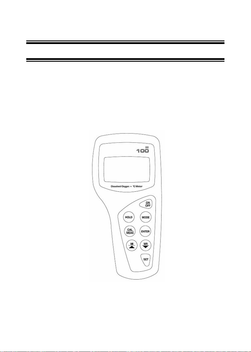
2 DISPLAY AND KEYPAD FUNCTIONS
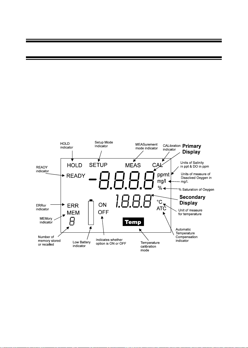
2.1 Display
The LCD has a primary and secondary display.
• The primary display shows the measured DO value either in mg/L, ppm or %,
depending on units of measurement selected.
• The secondary display shows the temperature in °C.
The display also shows error messages, keypad functions and program functions.
See Figure 1.
Figure 1: Full LCD Screen
2
Page 7
Instruction Manual DO 100
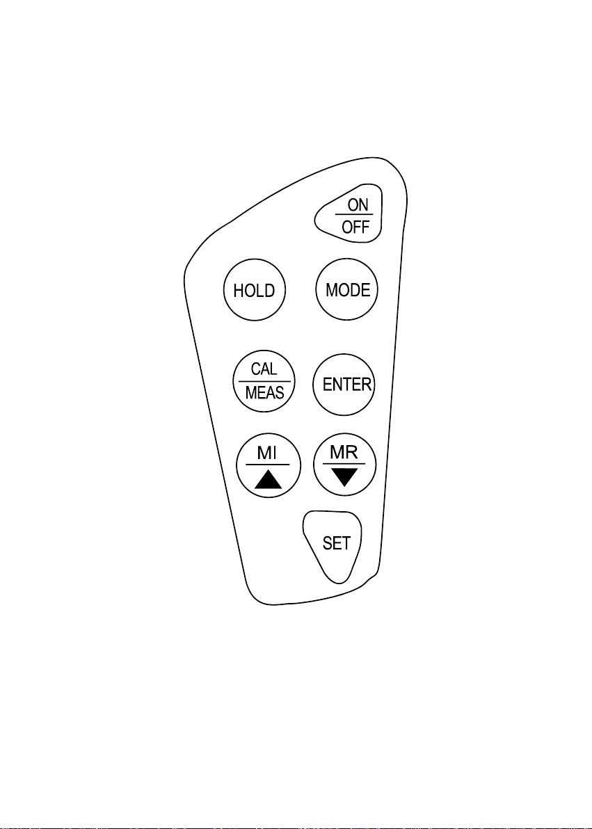
2.2 Keypad
The large membrane keypad makes the instrument easy to use. Each button, when pressed,
has a corresponding graphic indicator on the LCD. See Figure 2. Some buttons have several
functions depending on its mode of operation.
Key Function
ON/OFF Powers on and shuts off the meter. When you switch on the meter, the meter
HOLD 1. Freezes the measured reading. To activate, press HOLD while in
MODE 1. Selects the measurement parameter. Press MODE to toggle between %
CAL/MEAS 1. Toggles between Calibration and Measurement mode.
ENTER 1. Press to confirm your calibration values in Calibration mode.
MI & MR
/
SET Takes you into the SETUP mode.
starts up in the mode that you last switched off from. For example, if you shut
the meter off in mg/L measurement mode, the meter will be in mg/L
measurement mode when you switch the meter on.
measurement mode. To release, press HOLD again.
2. In its SETUP menu, this key takes you through the main menu.
Saturation and mg/L or ppm mode.
2. While in the CAL mode under mg/L or ppm measurement status, this key
will toggle between mg/L (ppm) calibration and temperature calibration
(refer to Section 4.1 on page 9 to 10.)
If you were in Measurement mode, press CAL/MEAS to enter Calibration
mode. To confirm calibration, press ENTER key.
To abort calibration, press CAL/MEAS key again to go back to
measurement mode.
2. While in SETUP, pressing CAL/MEAS takes you out directly into the
measurement mode.
2. While in SETUP, pressing ENTER key takes you through the various
menu AND through each sub-menu.
In measurement mode:
Press MI / to store values in mg/L or % Saturation values with its
corresponding temperature values in the memory. Up to 16 sets of values can
be stored.
Press MR/ to retrieve data from memory in LIFO method.
In Calibration mode:
Scrolls up and down values with each key press, or helps make selection.
3
Page 8
Instruction Manual DO 100
Figure 2: Keypad
4
Page 9
Instruction Manual DO 100
3 PREPARATION
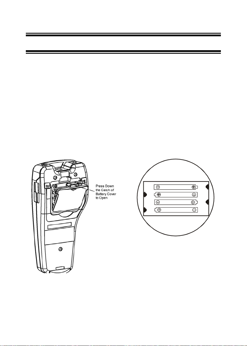
3.1 Inserting the Batteries
The DO 100 is packaged with 4 “AAA” alkaline batteries required for operation. To insert the
batteries into the meter, follow the procedure outlined below.
1. To open the battery compartment, press down the catch of the battery cover. See Figure
3a below.
2. Note the polarity and insert the batteries into the battery compartment correctly (Figure
3b).
3. Replace the battery cover into its original position, ensuring the catch is lock into its
position.
Your hand-held meter is now ready for operation.
Figure 3a: Back panel of meter
showing battery compartment
LR03 'AAA' (AM4)
MADE IN S'PORE
Figure 3b: Battery position
5
Page 10
Instruction Manual DO 100
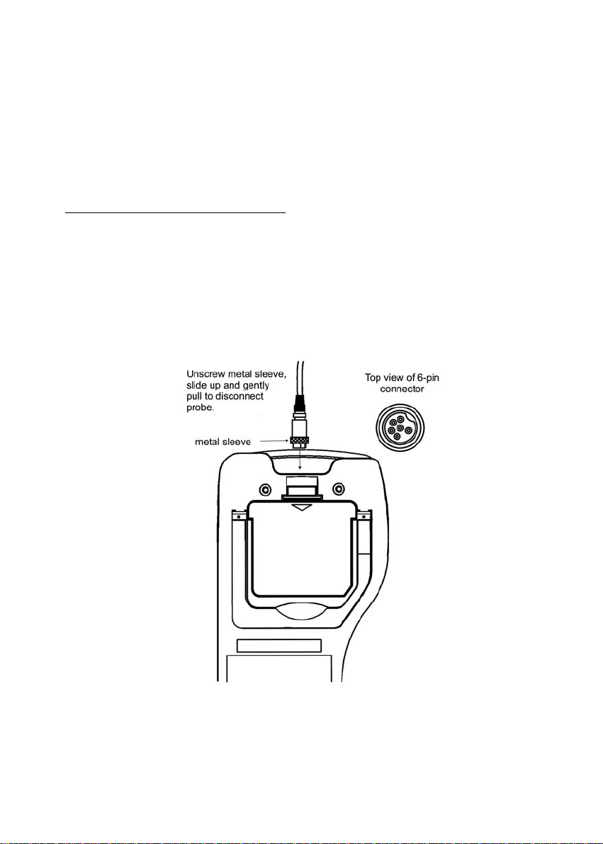
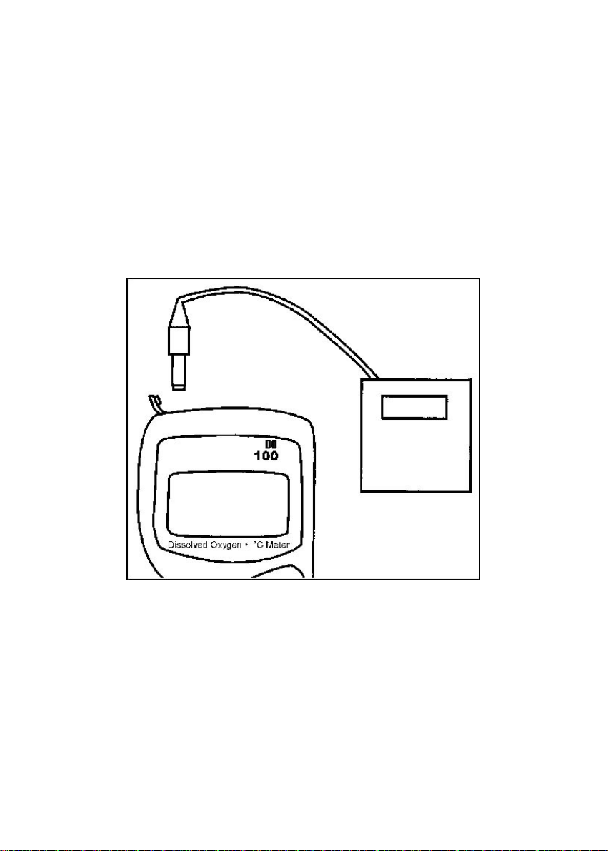
3.2 Connecting the Probe
The DO 100 uses a special notched 6-pin connector to attach the probe to the meter.
NOTE: Do not substitute other probes or electrodes. For replacement probe, see
the Section 14 “Accessories” on page 52.
NOTE: Keep connector dry and clean. Do not touch connector with soiled hands.
To connect the Dissolved Oxygen probe:
1. Line up the notch and 6 pins on the meter with the holes in the 6 pin connector. Push
down and screw the metal sleeve to lock the probe connector into place. See Figure 4.
2. To remove probe, unscrew the metal sleeve and slide up the probe connector. While
holding onto metal sleeve, pull probe away from the meter.
CAUTION: Do not pull on the probe cord or the probe wires might disconnect.
Figure 4 - Probe Connector
6
Page 11
Instruction Manual DO 100
3.3 Connecting the AC Adapter
The AC adapter is not included with your meter; see the Section 14 “Accessories” on page 52.
Ensure that the input mains voltage (110 or 220 V at 200 mA) matches your adapter
requirements.
1. Insert the AC jack as shown in Figure 5 below.
2. Switch off the meter before plugging the adapter into the power source. This safety
precaution protects the software in your meter.
3. Press the ON/OFF button to switch meter on.
Figure 5 - Using optional AC adapter
7
Page 12

Instruction Manual DO 100
4 CALIBRATION
The amount of oxygen dissolved in water will depend on its temperature, atmospheric
pressure and its salinity. While the pressure and salinity values are manually entered into the
instrument, the temperature is being measured by the probe. It is therefore very important
that the temperature is calibrated if necessary prior to the DO calibration.
The measurements of % Saturation of DO will linearly affect the measurement for DO in mg/L.
Hence calibration in % Saturation of DO should be carried out first. This is described in the
following section.
Before calibrating, press MODE key to select the correct measurement mode. There are 2
measurement modes for DO: mg/L or ppm, and % Saturation.
NOTE: All new calibrations will automatically over-ride existing calibration values.
8
Page 13
Instruction Manual DO 100
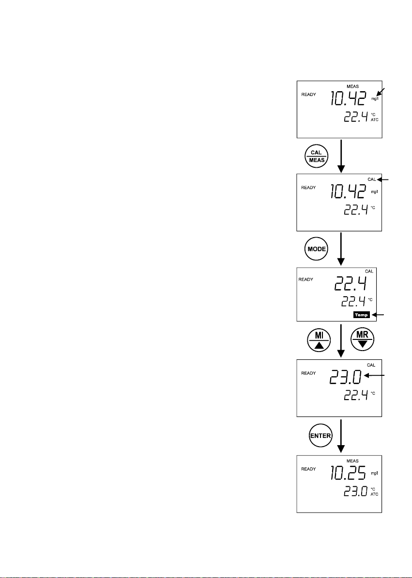
4.1 Temperature Calibration
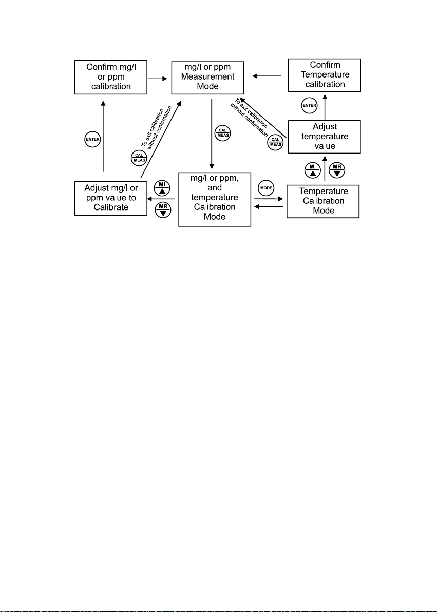
DO in mg/L is dependent on temperature, so it is first necessary to
calibrate or verify the temperature reading. Temperature calibration is
accessible from the mg/L or ppm measurement mode. This is
illustrated in the flow diagram in Figure 7.
The temperature sensor is part of the DO probe and the “ATC”
annunciator will light up on the LCD screen once the probe is
connected correctly to the meter.
1. Dip the DO probe into a solution with known temperature. Allow
sufficient time for the temperature to stabilise.
NOTE: Use an accurate temperature meter or bath to determine
the solution’s temperature.
2. Ensure that the meter is in measurement mode. Press MODE
key if necessary to select mg/L mode.
3. Press CAL key to go into calibration mode of mg/L. The primary
display shows the measured DO in mg/L and the secondary
display shows the temperature.
4. Press MODE key to go into temperature offset adjustment mode.
The primary and secondary displays will show the temperature
values. See Figure 6.
5. Press MI/ or MR/ key to set the correct temperature value.
NOTE: The meter allows a limit of ± 10 °C variation between the
original and the adjusted value.
6. Press ENTER key to confirm the adjusted temperature. The
temperature probe is now calibrated.
NOTE: To exit from Temperature Calibration mode without
confirming calibration, press CAL/MEAS key.
NOTE: Since temperature readings affect the accuracy of the
mg/L measurements, it is strongly recommended to
carry out a mg/L calibration after a temperature
calibration is done.
Figure 6: Temperature
Calibration
9
Page 14
Instruction Manual DO 100
Figure 7: Flow Diagram for Temperature and mg/L (ppm) Calibration
10
Page 15
Instruction Manual DO 100
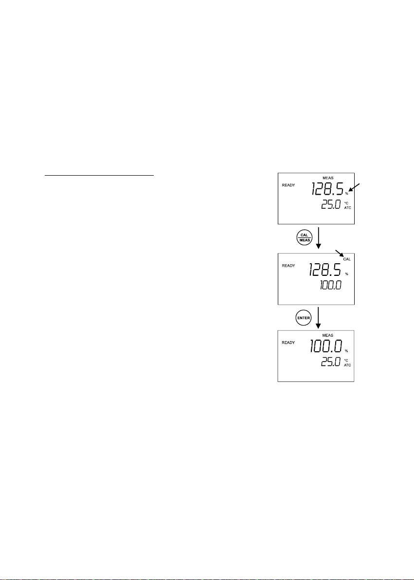
4.2 DO Calibration in Air (with ATC) –% Saturation Mode
You can calibrate this meter quickly and easily in air. The exact calibration value depends on
barometric pressure. The meter is set to a factory default of 760 mm Hg, which results in a
calibration value of 100% saturation in air.
NOTE: If the barometric pressure setting has been changed from 760 mm Hg, the calibration
value in air will automatically adjust to a value other than 100%. The adjusted value will be
correct for the new barometric pressure setting. See Section 8.23 for barometric pressure
setting.
To calibrate 100% Saturation:
1. Press MODE key to select % Saturation mode.
2. Rinse the probe well with deionised rinse water. For best
accuracy, wipe the end of the probe dry. Do not touch the
membrane.
3. Hold the probe in the air gently with the sensor facing
down and press CAL key to calibrate the meter. The LCD
will show a “CAL” mode. The primary display will show
the current value of measurement and the secondary
display will show “100.0” to which the meter is going to be
calibrated. Wait for the reading to stabilise.
4. Press ENTER key to confirm the calibration. The meter
automatically calibrates to 100% air saturation and
returns to the measurement mode.
NOTE: To exit from DO Calibration mode without
confirming calibration, DO NOT press ENTER.
Press CAL/MEAS instead.
Figure 8: Calibration for 100%
Saturation
11
Page 16
Instruction Manual DO 100
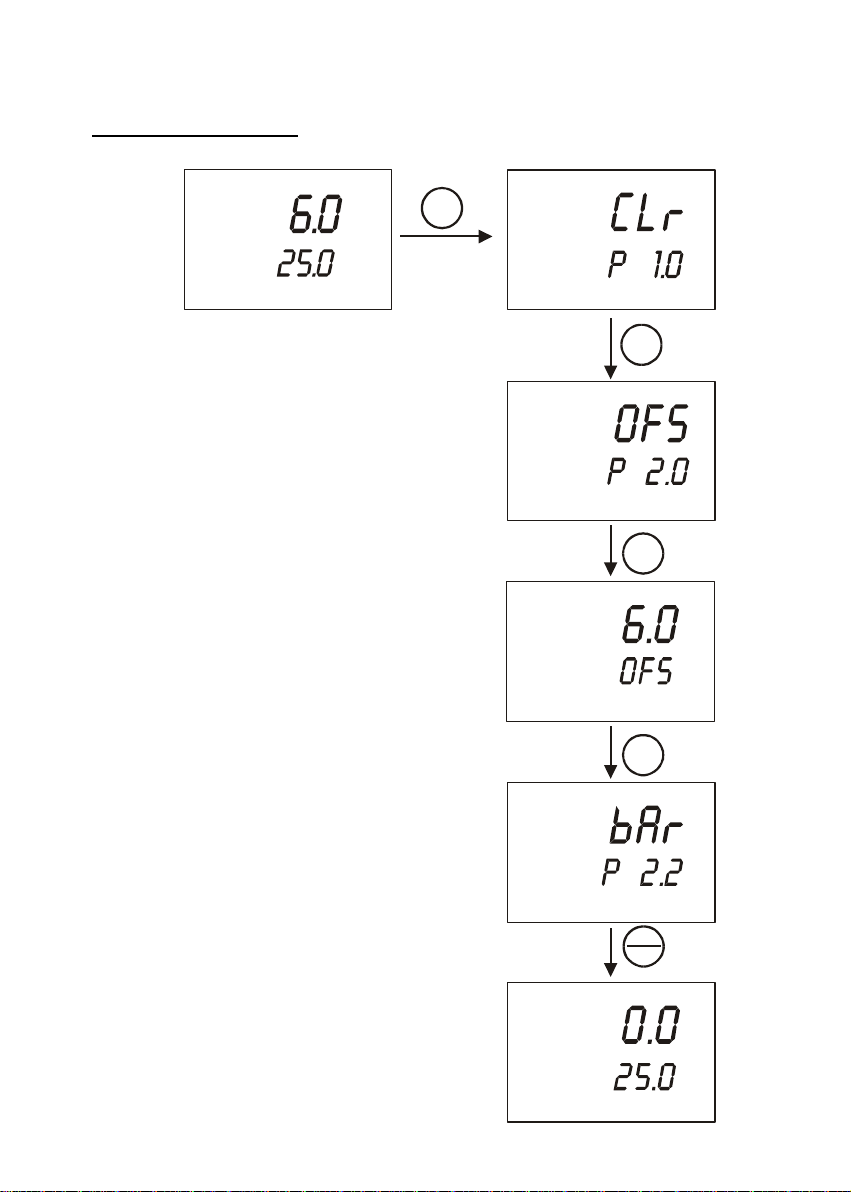
To calibrate 0% Saturation:
READY
MEAS
%
SET
SETUP
°C
ATC
MEM
OFF
1. Power on the unit and immerse the DO probe in
0% solution. Ensure that the tip of the probe is
Figure 9: Calibration for 0.0%
Saturation
ENTER
SETUP
completely immersed. Stir gently to create a
homogenous solution. Wait for the reading to
stabilise. It should be less than 10%.
2. Press SET key once to go to SETUP mode. The
SETUP indicator will appear above the primary
display.
3. Press ENTER key once. The “OFS- P2.0”
screen should appear.
4. Press ENTER key once to enter zero-point
SETUP
READY
ENTER
%
calibration mode. Wait for the reading to
stabilise. If the READY indicator feature is
enabled, it will appear when the reading is
stable (see Ready indicator setup in section
8.1.7.).
5. Press ENTER key once. The meter
SETUP
ENTER
automatically calibrates to 0.0% saturation. The
next screen should show “bAr- P2.2”.
6. Press CAL/MEAS key once to exit out of
SETUP mode. The meter is now in
measurement mode and should display 0.0%
value.
CAL
MEAS
NOTE: You can offset your % DO Calibration; see
page 24 for directions.
READY
MEAS
%
°C
ATC
12
Page 17
Instruction Manual DO 100
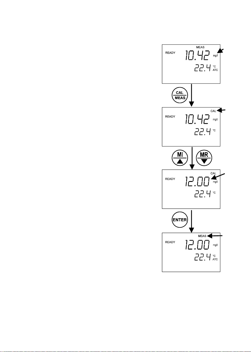
4.3 DO Calibration in mg/L Mode
As mentioned in the beginning of this section, the amount of
oxygen dissolved in a liquid will depend on its temperature,
pressure and salinity. It is therefore very important to set
these parameters correctly before attempting to do a
calibration.
Temperature is measured by the meter automatically.
Therefore it is important to do a Temperature Calibration (as
described in Section 4.1) before attempting DO calibration.
Pressure and salinity values are keyed in manually as
described in Sections 8.2.2 and 8.2.3.
1. From the measurement mode, press MODE key to
select mg/L.
2. Rinse the probe well with deionised rinse water. For
best accuracy, wipe the end of the probe dry. Do not
touch the membrane.
3. Dip the probe into a solution where DO value is known.
4. Wait until the reading stabilises. Press CAL key.
5. Adjust to the required value by pressing MI/ or MR/
key.
6. Press ENTER to confirm the calibration. See Figure
10.
NOTE: To exit from DO Calibration mode without
confirming calibration, press CAL/MEAS key.
13
Figure 10: DO Calibration
Page 18
Instruction Manual DO 100
5 MEASUREMENT
During measurement, care must be taken not to allow the membrane of the DO probe touch
any surface. It is always advisable to insert the probe guard (refer to Figure 33 and 34 o n
pages 40 and 41). The probe can either be fully or partially immersed in the solution.
The READY indicator appears on the display when the readings stabilise. It will turn off if the
readings start to fluctuate.
NOTE: It is important that the sample is stirred constantly to allow it to flow past the
membrane for better readings.
5.1 Taking Measurement
1. Rinse the probe with deionised or distilled water
before use to remove any impurities adhering to the
probe body. If it is dehydrated, soak it for 30
minutes in tap water.
2. Switch on the meter. The MEAS annunciator
appears on the top of the LCD. The ATC indicator
appears in the lower right hand corner to indicate
Automatic Temperature Compensation. See figure
on right.
3. Dip the probe into the sample.
NOTE: When dipping the probe into the sample, make
sure the tip of the probe is completely immersed. Stir the
sample gently to create a homogenous sample. Be sure
to tap probe very gently to remove air bubbles. Air
bubbles will cause errors in the reading.
4. Allow time for the reading to stabilise. Note the
reading on the display. When the reading is stable,
the READY annunciator appears.
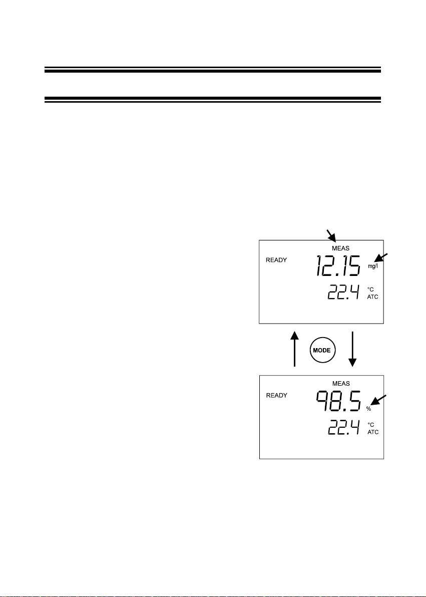
5. To toggle between % Saturation and mg/L
measurement mode, press the MODE key. See
Figure 11.
Figure 11: Taking Measurement
14
Page 19

Instruction Manual DO 100
6 HOLD FUNCTION
This feature lets you freeze the value of the DO
reading for a delayed observation. HOLD can be used
any time when in MEAS mode.
1. To hold a measurement, press the HOLD key
while in measurement mode. “HOLD” will appear
on the display.
See Figure 12.
2. To release the held value, press HOLD again.
Continue to take measurements.
NOTE: This meter shuts off automatically after
20 minutes of last key press. If the meter
is shut off either automatically or
manually, the HOLD value will be lost.
For longer storage, use the memory
functions.
Figure 12: HOLD Function
15
Page 20

Instruction Manual DO 100
7 MEMORY FUNCTION
The DO 100 can store up to 16 sets of data. Each data
stored can either be in % Saturation, mg/L or ppm together
with its respective temperature reading taken at that
moment.
Stored data can be easily recalled based on LIFO (Last-InFirst-Out) system.
7.1 Data Input
To clear all data from memory, refer to Sections 8.1.1 (page
23) or 8.2.1 (page 31) on the procedure.
1. Switch on the meter by pressing ON/OFF key.
2. Ensure the meter is in the appropriate measurement
mode, either mg/L or % Saturation. Press MODE key
for the desired measurement mode.
3. Place the probe into the sample to be measured.
4. After the reading is stabilised, indicated by the READY
annunciator, press MI/ key. The MEM annunciator
will flash with a number indicating that the data has
been stored. See figure on right.
5. Place the probe into another sample and repeat from
step 2 above.
NOTE: The above illustration will be used in the next
Section, Memory Recall.
NOTE:
The number counter below MEM annunciator will increase
to 16 according to the following symbols:
16
Figure 13 Memory Input
Page 21

Instruction Manual DO 100
Data No. MEM Symbol Data No. MEM Symbol
1 1 9 9
2 2 10 A
3 3 11 b
4 4 12 C
5 5 13 d
6 6 14 E
7 7 15 F
8 8 16 0
Since the memory management is based on LIFO, once memory is full, the first value that
was stored in the memory will be erased to create space for the new value to be input.
NOTE: Data input will remain even after the meter is switched off.
17
Page 22

Instruction Manual DO 100
7.2 Memory Recall
Based on LIFO memory management, the last data input
into memory will be recalled first. The data recalled will
depend on which measurement mode (mg/L or %
Saturation) the meter is presently in. For example, if the
meter is in % Saturation measurement mode, pressing
MR/ key will recall data recorded in that measurement
mode only.
NOTE: For the following illustration, please note data
recorded Section 7.1, Data Input.
1. Ensure the meter is in MEAS mode.
2. Switch to the appropriate measurement mode (mg/L
or % Saturation) by pressing MODE key.
3. Press MR/ key to recall the last data recorded.
4. Press MR/ key again for next recorded data.
5. Repeat MR/ if necessary. See Figure 14.
18
Figure 14: Memory Recall
Page 23

Instruction Manual DO 100
To recall data input in the next measurement mode note the
following procedure:
6. Press CAL/MEAS key to exit memory mode.
7. Press MODE key to toggle to the other measurement
mode.
8. Press MR/ to recall data recorded in that
measurement mode.
9. Press MR/ key again for next recorded data. See
Figure 15.
NOTE: To exit Memory mode, press CAL/MEAS key.
The meter toggles back to measurement mode
and is ready for measurement again.
Figure 15: Memory Recall
19
Page 24

Instruction Manual DO 100
8 SET FUNCTION
There are two setup parameters for each of the two measurement modes (% Saturation and
mg/L or ppm). This is due to the different properties associated with each unit of
measurement.
The SETUP function is a powerful feature that allows you to customise the meter to your
needs. For example you can choose to:
• Clear memory
• Adjust offset
• Input salinity value (in mg/L measurement mode)
• Choose different units of measurement for atmospheric pressure
(either in mm Hg or kPA) and adjust its value according to the
location
• Check for electrode’s calibration slope, offset and millivolt (mV)
value
• Change between mg/L or ppm measurement mode
• Activate or deactivate stabilising (READY) feature
• Activate or deactivate Power Auto-off feature
• Clear all parameters and reset the meter back to factory default
SET function will be explained in the following 2 sub-sections:
1. SET function in % Saturation measurement mode
2. SET function in mg/L or ppm measurement mode
20
Page 25

Instruction Manual DO 100
8.1 SET Function in % Saturation Measurement Mode
This part of the SETUP function allows display of values and the changing of parameters
unique to the % Saturation measurement mode. Figure 16 on the following page shows the
flow diagram of the SETUP menu.
To access SETUP menu:
1. Switch on the meter.
2. Ensure that the measurement mode is in % Saturation. If not, press MODE key to
change from mg/L or ppm measurement mode to % Saturation.
3. Press SET key to enter the first level in its setup menu.
4. To move from one menu to the next without changing any parameter, simply press
HOLD key as shown in Figure 16.
21
Page 26

Instruction Manual DO 100
5. Press ENTER and MI/ or MR/ key to enter the menu to change parameter or simply
to view the value. At any level, press CAL/MEAS to exit setup function and go back to
the measurement mode.
Figure 16: Flow Diagram in SETUP Menu
22
Page 27

Instruction Manual DO 100
8.1.1 P 1.0: Clr
This clears all memory data input keyed during
measurement. Default setting is OFF.
1. Press SET key to enter the first level in its setup
menu.
2. Press MI/ or MR/ key to switch to “ON”.
3. Press ENTER key to confirm deleting all memory
data.
4. The meter will pause briefly and move on to the next
menu.
See Figure 17.
NOTE: Press HOLD key to skip this operation and
move on to the next menu, or press
CAL/MEAS key to exit setup menu to go
back to measurement mode.
NOTE: The data cleared relates to the input taken
while the meter was in % Saturation
measurement mode. To clear data input
in mg/L or ppm measurement mode, switch
the measurement mode to mg/L or ppm
and refer to Section 8.2.1 on page 31.
Figure 17: Clear Memory Menu
23
Page 28
Instruction Manual DO 100
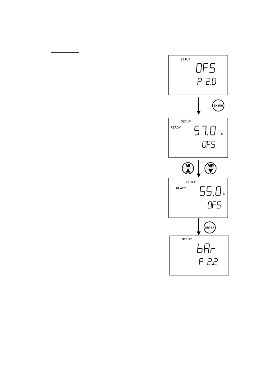
8.1.2 P 2.0: OFS
This is a useful feature that allows you to offset meter’s
value when cross referenced with another DO meter. That
way, it can be standardised without you having to perform
manual calculation.
1. Once you come to the setup menu shown in Figure 18,
press ENTER.
2. Dip the DO probe in a sample solution.
3. Check the reading of another DO meter being used as
a reference. This reference meter should have its
probe immersed in the same sample solution and at
the same depth.
4. Use MI/ or MR/ key to adjust displayed value to
match with the reference meter.
5. Press ENTER key to confirm offset value.
6. The meter will accept the value and move on to the
next menu. See Figure 18.
NOTE: Press HOLD key to skip this operation and
move on to the next menu, or press
CAL/MEAS key to exit setup menu to go back
to measurement mode.
Figure 18: Adjusting Offset
Menu
24
Page 29

Instruction Manual DO 100
8.1.3 P 2.2: bAr
This menu allows you to do two things:
• Select the appropriate unit of measurement of pressure --- either mm Hg or
kPA.
• Keying of actual atmospheric pressure value based on the altitude of the
location.
This is an important feature as DO is dependent on pressure (refer Section 12.1 on page
48).The DO 100 will use this input to compensate for the measured value automatically
without having to refer to tables.
1. Once you come to the SETUP menu shown in Figure 19 on the following page, press
ENTER.
2. Press MI/ or MR/ key to select “Hg” or “PA” as unit of pressure measurement.
3. Press ENTER key to go into the next level.
4. Press MI/ or MR/ key to adjust value accordingly to the location’s actual atmospheric
pressure.
NOTE: The range for atmospheric correction ranges from 555 to 808 mm Hg or
74 to 108 kPA.
5. Press ENTER key to confirm value.
6. The meter will accept the value and move on to the next menu.
NOTE: Press HOLD key to skip any part of the operation and move on to the
next menu, or press CAL/MEAS key to exit setup menu to go back to
measurement mode.
25
Page 30

Instruction Manual DO 100
Figure 19: Selecting Unit of Pressure & Adjusting its Value
26
Page 31

Instruction Manual DO 100
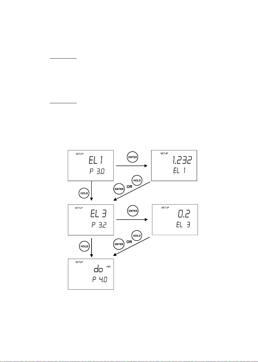
REMARKS: The following 3 menus display the condition of the DO probe
from the last calibration performed. Refer Figure 20 on the following page for
flow diagram.
8.1.4 P 3.0: EL 1
This menu displays the slope of probe as a ratio of the ideal to the measured value.
1. Once you come to the [EL 1, P 3.0] menu shown in Figure 20, press ENTER.
2. The LCD will show the ratio value. Factor of 1 is the ideal value.
3. Press ENTER or HOLD key to go into the next menu.
8.1.5 P 3.1: EL 2
This menu displays the offset value that has been keyed in the OFS (P 2.0) SETUP menu.
This is useful to compare the status of the probe.
1. Once you come to the [EL 2, P 3.1] menu shown in Figure 20, press ENTER.
2. The LCD will show the offset value.
3. Press ENTER or HOLD key to go into the next menu.
8.1.6 P 3.2: EL 3
This menu displays the actual offset value in mV for the last zero point calibration.
1. Once you come to the [EL 3, P 3.2] menu shown in Figure 20, press ENTER.
2. The LCD will show the offset value in mV.
3. Press ENTER or MODE key to go into the next menu.
27
Page 32

Instruction Manual DO 100
Figure 20: Checking Electrode Status in EL Menu
28
Page 33

Instruction Manual DO 100
8.1.7 P 4.1: rdY
You can activate or deactivate the stabilising feature in the
meter in this menu.
1. Once you come to the setup menu shown in Figure 21,
press ENTER.
2. Press MI/ or MR/ key to toggle between ON or OFF.
3. Press ENTER or MODE key to go into the next menu.
Figure 21: READY
8.1.8 P 4.2: A.oFF
The meter has a Power Auto-off feature that switches off the unit
20 minutes after the last key press. In situation where longer
period of time is needed to take measurement, the power Autooff feature can be switched off in this menu.
1. Once the [A.oFF P4.2] menu is reached (see Figure 22),
press MI/ or MR/ key to turn Auto-off feature ON (or
OFF).
2. Press ENTER key to confirm selection.
3. The meter will accept and move on to the next menu.
NOTE: Press HOLD key to skip any part of the operation
and move on to the next menu, or press
CAL/MEAS key to exit setup menu to go back to
measurement mode.
Figure 22: Auto-Off
29
Page 34

Instruction Manual DO 100
8.1.9 P 5.0: r.Set
This allows you to clear all parameters programmed above
and re-set it to factory default values.
1. Once the [r.Set P 5.0] menu is reached (see Figure
23), press MI/ or MR/ key to turn reset feature ON
(or OFF).
2. Press ENTER key to confirm selection.
3. The meter will clear all values and go back to
measurement mode.
Figure 23: Re-set All Values
30
Page 35

Instruction Manual DO 100
8.2 SET Function in mg/L or ppm Measurement Mode
This part of the SETUP function allows display of values and the changing of parameters
unique to the mg/L measurement mode. Figure 25 on the following page shows the flow
diagram of the SETUP menu.
To access SETUP menu:
1. Switch on the meter.
2. Press MODE key to select mg/L.
3. Press SET key to enter the first level in its setup menu.
4. To move from one menu to the next without cha nging
any parameter, simply press HOLD key as shown in
Figure 25. Press ENTER or MI/ or MR/ key to
enter the menu to change parameter or simply to view
the value.
5. At any level, press CAL/MEAS to exit setup function
and go back to the measurement mode.
8.2.1 P 1.0: Clr
This clears all memory data input keyed during
measurement. Default setting is OFF.
1. Press MI/ or MR/ key to switch to “ON”.
2. Press ENTER key to confirm deleting all memory data.
3. The meter will pause briefly and move on to the next
menu.
See Figure 24.
NOTE: Press HOLD key to skip this operation and
move on to the next menu, or press
CAL/MEAS key to exit setup menu to go back
to measurement mode.
NOTE: The data cleared relates to the input taken
while the meter was in mg/L or ppm
measurement mode. To clear data input in %
Saturation measurement mode, switch the
measurement mode to % Saturation and refer to Section 8.1.1 on page
23.
Figure 24: Clear Menu
31
Page 36

Instruction Manual DO 100
Figure 25: Flow Diagram in SETUP Menu (mg/L or ppm)
32
Page 37

Instruction Manual DO 100
8.2.2 P 2.1: SAL
This is a useful feature that allows you to key in the salinity value
of the sample solution to be measured.
1. Once you come to the [SAL, P 2.1] menu shown in Figure 26,
press ENTER.
2. Use MI/ or MR/ key to set the Salinity value in ppt of the
liquid where DO is being measured. Salinity correction values
from 0.0 to 50.0 ppt can be entered.
3. Press ENTER key to confirm the value.
4. The meter will accept the value and move on to the next
menu.
NOTE: Press HOLD key to skip this operation and move on
to the next menu, or press CAL/MEAS key to exit
setup menu to go back to measurement mode.
8.2.3 P 2.2: bAr
This menu allows:
• Selecting the prefered unit of pressure--either mm Hg or
Figure 26: Adjusting for Salinity
Value
kPA.
• Keying of actual atmospheric pressure value based on the altitude of the
location.
This is an important feature as DO is dependent on pressure (refer Section 12.1 on page 48).
Without you having to refer to tables, the DO 100 will use this input to compensate for the
measured value automatically.
1. Once you come to the [bAr P 2.2] menu shown in Figure 27, press ENTER.
2. Press MI/ or MR/ key to select “Hg” or “PA” as unit of pressure measurement.
3. Press ENTER key to go into the next level.
4. Press MI/ or MR/ key to adjust value accordingly to the location’s actual atmospheric
pressure.
NOTE: The range for atmospheric correction ranges from 555 to 808 mm Hg or
74 to 108 kPA.
5. Press ENTER key to confirm value.
6. The meter will accept the value and move on to the next menu.
Figure 27 on the following page shows the flow diagram on this menu.
33
Page 38

Instruction Manual DO 100
NOTE: Press HOLD key to skip any part of the operation and move on to the
next menu, or press CAL/MEAS key to exit setup menu to go back to
measurement mode.
Figure 27: Select Units for Pressure and Adjust Its Value
34
Page 39
Instruction Manual DO 100
REMARKS: The following 2 menus display the condition of the DO probe
from the last calibration performed. Refer Figure 28 for flow diagram.
8.2.4 P 3.0: EL 1
This menu displays the slope of probe as a ratio of ideal to its measured value.
1. Once you come to the [EL 1, P 3.0] menu shown in Figure 28, press ENTER.
2. The LCD will show the ratio value. Factor of 1 is its ideal value.
3. Press ENTER or HOLD key to go into the next menu.
8.2.5 P 3.2: EL 3
This menu displays the actual offset value in mV for its last zero point calibration.
1. Once you come to the [EL 3, P 3.2] menu shown in Figure 28, press ENTER.
2. The LCD will show the offset value in mV.
3. Press ENTER or MODE key to go into the next menu.
Figure 28: Checking Electrode Status
35
Page 40

Instruction Manual DO 100
8.2.6 P 4.0: do
This menu allows you to choose between mg/L or ppm as unit
of measurement.
1. Press ENTER.
2. Press MI/ or MR/ key to select “mg/L” or “ppm” as
unit of measurement.
3. Press ENTER key to go into the next level. See Figure
29.
Figure 29: Selecting mg/L or
ppm as units of measure
8.2.7 P 4.1: rdY
You can activate or deactivate the READY (rdY) stabilising
feature in the meter in this menu.
1. Once you come to the [rdY, P 4.1] menu shown in
Figure 30, press ENTER.
2. Press MI/ or MR/ key to toggle between ON or
OFF.
3. Press ENTER or MODE key to go into the next menu.
Figure 30: READY
36
Page 41

Instruction Manual DO 100
8.2.8 P 4.2: A.oFF
The meter has a Power Auto-off feature that switches off the unit
20 minutes after the last key press. In situation where longer
period of time is needed to take measurement, the power Autooff feature can be switched off in this menu.
1. Once the [A.oFF P 4.2] menu is reached (see Figure 31) ,
press MI/ or MR/ key to turn Auto-off feature ON (or
OFF).
2. Press ENTER key to confirm selection.
3. The meter will accept and move on to the next menu.
NOTE: Press HOLD key to skip any part of the operation
and move on to the next menu, or press
CAL/MEAS key to exit setup menu to go back to
measurement mode.
Figure 31: Auto-Off
8.2.9 P 5.0: r.Set
This allows you to clear all parameters programmed above and
re-set it to factory default values.
1. Once the [r.Set, P 5.0] menu is reached (see Figure 32),
press MI/ or MR/ key to turn reset feature ON (or OFF).
2. Press ENTER key to confirm selection.
3. The meter will clear all values and go back to measurement
mode.
Figure 32: Reset All Values
37
Page 42

Instruction Manual DO 100
9 DISSOLVED OXYGEN PROBE
9.1 Dissolved Oxygen Principle
The probe is a galvanic measuring element which produces an output proportional to the
oxygen present in the medium in which it is placed. The galvanic probe design lets you take
measurements immediately – without the typical 15 minute wait of other dissolved oxygen
probes.
The probe consists of two parts:
• An upper part consisting of an anode, a cathode, and cable.
• A lower part consisting of a membrane cap, membrane, and electrolyte solution.
See Figure 33.
Oxygen diffuses through the membrane onto the cathode, where it is consumed. This process
produces an electrical current which flows through the cable to the meter. The electric current
produced is proportional to the oxygen that passes through the membrane and the layer of
electrolyte. This makes it possible to measure the partial pressure of oxygen in the sample at
a given temperature.
Since the DO in the sample is consumed by the cathode it is essential that a new sample
must flow past the membrane of the probe to prevent the occurrence of false readings. The
probe uses very little oxygen for its measurement. This enables it to function correctly with
liquid movement as low as 2.5 cm/sec.
The permeability of the membrane to oxygen varies greatly with temperature. Therefore
compensation is needed for this variation. The DO probe comes with an in-built Temperature
Compensation for the membrane variation.
38
Page 43

Instruction Manual DO 100
9.2 Probe Care
Under typical operating conditions, the probe should last for several years. Proper care and
maintenance will help you receive the maximum probe life and ensure more accurate
readings.
Since any deposits on the membrane surface act as a barrier to oxygen diffusing through the
membrane, the membrane must be cleaned at regular intervals to assure maximum reliability.
After using the probe, rinse the probe in clean water and wipe it with a soft cloth or paper to
avoid any hardening of deposits. If growth develops on the probe, use a disinfecting chemical
to clean.
NOTE
Although the membrane is strong and not easily damaged, wipe it gently while cleaning it. If
the membrane is damaged or torn, the probe will no longer function.
There are no special probe storage requirements.
39
Page 44
Instruction Manual DO 100
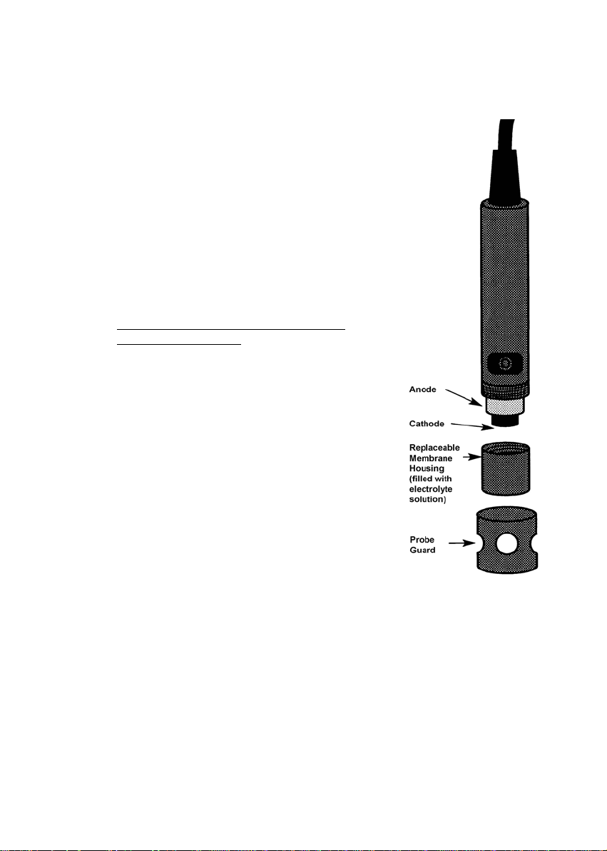
9.3 Membrane Housing Replacement
Replacement of the membrane cap housing/ membrane is
required only when you cannot calibrate the probe, or if the
membrane is damaged.
Typical membrane damages are punctures or wrinkles
caused during measurements or cleaning. For more
information see trouble-shooting guides in sections 9.6 and
10.
Your new DO probe comes with a replacement membrane
housing. To order more replacement membrane housing,
see the “Accessories” section on page 52.
9.3.1 To replace the membrane cap (with pre-
installed membrane) -
Replacement is much easier with single membrane housing.
Simply unscrew the old membrane cap housing, add solution
to the new housing, and screw the new cap housing in place.
1. Fill the membrane cap housing with electrolyte solution
and inspect the bottom for leaks. If the solution drops
are leaking from the membrane, use a new cap
housing.
2. If the assembly is leak-free, fill the membrane cap
housing with electrolyte to the brim.
3. Tap the side of the housing gently to remove any air
bubble that may be sticking to the membrane.
4. Screw the cap onto the probe. Excess electrolyte will
drain out.
5. Replace probe guard.
6. Calibrate the probe (see section 4) after the %
saturation readings have stabilised.
Figure 33: Positioning of O-ring
& membrane
40
Page 45
Instruction Manual DO 100
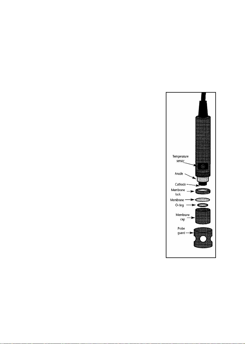
9.4 Membrane/O-ring Replacement (Optional Procedure)
It is recommended only experienced service personnel can perform this procedure.
This procedure is OPTIONAL, and should only be performed if you have new membrane and
O-ring. You are also required to have a membrane installation tool. These items are available
as optional accessories in the “Accessories” section.
1. Pull off the probe guard. See Figure 34.
2. Unscrew the membrane cap from the probe.
3. Hold the probe under hot running water and brush
away the white oxide on the cylindrical anode with a
stiff plastic brush – do not use metal cleaning
material.
4. If the cathode has any deposits, remove them with a
light scouring powder. Do not polish the cathode.
5. Using the installation tool, unscrew and remove the
membrane lock from the membrane cap. See Figure
35 on the following page.
6. Remove the membrane and O-ring. Discard both.
7. Rinse the membrane cap and membrane lock in tap
water.
8. Install a new O-ring inside the membrane cap.
9. Install a new membrane. Make sure the membrane
covers the O-ring all around its circumference. See
Figure 36 on the following page.
41
Figure 34: Positioning of O-ring
& membrane
Page 46

Instruction Manual DO 100
10. Using the installation tool, screw the membrane
lock back into the cap. Tighten the lock firmly over
the membrane and O-ring, but do not over tighten.
11. Inspect the membrane for wrinkles. If wrinkles
Close
Installation tool
Open
exist, remove the membrane and repeat steps 8 –
11.
12. Fill the membrane cap with water and inspect the
bottom for leaks. If water drops are leaking from
the membrane, re-seal the membrane on the Oring (repeat steps 8 – 11, for membrane
replacement only).
Insert installa t ion
tool into slot s on
membrane lock.
Then unscrew
membrane lock
from membrane
cap
13. If the assembly is leak-free, empty the water and
fill the membrane cap with electrolyte to the brim.
14. Tap the side of the housing gently to remove any
air bubble that may be sticking to the membrane.
15. Screw the cap onto the probe. Excess electrolyte
will drain out.
Figure 35: Use Tool to take out (or put in)
membrane
16. Replace probe guard.
17. Calibrate the probe (see section 4) after the %
saturation readings have stabilised.
NOTE
Membranes can only be used once. When a
membrane cap is screwed onto the probe, the
membrane is stretched by the cathode. If the same Oring and the membrane is used a second time it will not
fit perfectly onto the cathode. This will result in erratic
readings.
Figure 36: Parts of electrode
showing O-ring, membrane & lock
42
Page 47

Instruction Manual DO 100
9.5 Electrolyte Solution
The electrolyte solution in your probe’s cap will deplete on usage and will need to be replaced
periodically.
Your new DO probe comes with accessories of one 50-ml replacement electrolyte solution
and a spare membrane cap. The replacement electrolyte comes premixed and ready to use.
To order more electrolyte solution, see “Accessories” section.
43
Page 48

Instruction Manual DO 100
9.6 DO Probe Troubleshooting Table
When experiencing difficulties with the equipment, keep in mind of the following:
1. Check for the obvious, such as physical condition of the probe, any signs of damage to
the cable, power and signal connections etc.
2. Determine whether it is the probe, meter or the surrounding environment that is causing
the problem.
The following troubleshooting table identifies most of the problems likely to occur:
Problem Probable Causes Solution
1. Fluctuating readings
when probe is shaken
or bumped lightly or
when membrane is
touched.
2. With membrane cap
removed and probe
internals thoroughly
dry, the reading from
the probe is not zero
and/or is erratic.
Probe has lost electrolyte – a
sloshing noise will be heard
when the probe is shaken.
Torn or damaged membrane.
Wet connections in the wiring
or within probe. See Problem
2.
Moisture has entered the
system – either into the probe
itself or at junctions or points
in the cable. This moisture
creates a secondary galvanic
action in addition to that
produced by the probe and
results in non-zero or erratic
readings.
Determine whether it is a physical or
electronic problem with the probe.
Unscrew the membrane cap, discard
the electrolyte, membrane and Oring.
Dry the internals of the probe,
especially the cathode with a soft
cloth.
Switch the meter ON and observe the
display.
If the display reads zero, the probe
and cable circuitry are alright.
Service probe and change
membrane.
If the display does not read zero, but
some other value, then there is
probably moisture somewhere. See
Problem 2.
Locate the source of moisture by
process of elimination. If moisture
has entered a junction box or a cable
joint, thoroughly dry out the area and
take measures to prevent
reoccurrence.
44
Page 49

Instruction Manual DO 100
Problem Probable Causes Solution
3. It is not possible to
calibrate the probe in
air – the display will
not read high enough
after fully adjusting the
offset.
4. Display values are
erratic when
membrane is lightly
touched. Membrane
has bulged outwards.
Probe has dried out – no
electrolyte inside.
Probe is overdue for servicing
– excessive build-up of anode
oxide.
A deposit has built-up on the
silver cathode, which is
inhibiting the reduction of
oxygen at its surface.
The membrane has been
damaged.
Service probe and change
membrane. Use a stiff nylon brush to
remove the oxide built-up from the
anode. Do not use a wire brush. It is
only necessary to remove the loose
oxide layer. If it is suspected that the
anode is badly corroded, replace with
a new DO probe. Remember to
tighten the nut under the anode
before fitting a new anode.
If it is suspected that a deposit is
coating the silver cathode, clean the
cathode with 400 grit wet/dry emery
paper or with some scouring powder.
The deposit is sometimes visible as a
brownish stain on the surface of the
cathode.
If the membrane has been damaged
change it and service the probe.
NOTE: The cathode must not be polished – the surface must remain dull (do not use a wire
brush).
45
Page 50

Instruction Manual DO 100
10 TROUBLESHOOTING
Problem Cause Solution
No display when
turned on
Unstable readings Insufficient reference electrolyte in
Slow response Dirty / Oily probe or dirty membrane. Clean probe. See Section 9.3 on page
Meter not
responding to key
press.
Batteries not in place
Batteries not in correct polarity
(+ and -).
Weak batteries
probe.
Broken probe.
External noise pickup or induction
caused by nearby electric motor.
Dirty probe.
HOLD mode in operation.
Damaged keypad.
Internal program error.
Check that batteries are in place and
making good contact.
Reinsert batteries with correct polarity.
Replace batteries or attach optional AC
adapter.
Fill probe with reference electrolyte.
Replace the probe.
Move or switch off interfering motor.
Clean probe. See Section 9.3 on page
39.
39.
Cancel HOLD mode by pressing it
again.
Return meter.
Reset all internal programs by re-
inserting batteries.
46
Page 51

Instruction Manual DO 100
11 ERROR MESSAGES
LCD Display Indicates Cause Solution
Err 1 (in primary
display)
Err. 2 (in primary
display)
Err. 3 (in primary
display)
Err. 4 (in primary
display)
Err annunciator Unrecognised input
CAL & Err
annunciators
blink.
Battery indicator
lights up.
Battery indicator
blinks
Memory write error. Instrument too old (> 10
Memory checksum
error.
A/D converter error. Hardware error. Turn meter on and off
Keypad error. One or more keys on
from keypad
Calibration error. Wrong value input at
Low battery level. Need new batteries or
Low battery level. Need new batteries or
years). Hardware
failure.
Hardware failure. Turn meter on and off
the keypad are stuck.
Wrong input in selected
mode.
calibration.
Dirty probe.
battery connection is
bad.
battery connection is
bad.
Turn meter on and off
again. If message persists,
return unit*.
again. If message persists,
return unit*.
again. If message persists,
return unit*.
Turn meter on and off
again. If message persists,
return unit*.
Release key. Select valid
operations depending on
mode.
Check your input value,
clean probe.
See Calibration sections or
Probe Maintenance
section.
Clean battery contacts.
Replace batteries with fresh
ones, noting polarity.
Clean battery contacts.
Replace batteries with fresh
ones, noting polarity.
* See Section 15 “Warranty” and Section 16 “Return of Items” on page 54.
If an error message appears in the primary display (the upper row of larger digits), switching
off the meter and switching it on again may eliminate the error message.
If error persists, or the meter shows incorrect values, return the meter.
For a complete diagram of the display, see Figure 1 on page 2.
47
Page 52

Instruction Manual DO 100
12 ADDITIONAL INFORMATION
12.1 Dissolved Oxygen
12.1.1 General Information
Dissolved Oxygen (DO) refers to the volume of oxygen that is cont ained in water. There are
two main sources of DO in water: from atmosphere and photosynthesis. Waves and tumbling
water mix air into the water where oxygen readily dissolves until saturation occurs. Oxygen is
also produced by aquatic plants and algae as a by-product of photosynthesis.
The amount of DO that can be held by water depends on 3 factors: water temperature,
salinity, and atmospheric pressure.
1. Amount of DO increases with decreasing temperature (colder water holds more oxygen);
2. Amount of DO increases with decreasing salinity (freshwater holds more oxygen than
saltwater does);
3. Amount of DO decreases with decreasing atmospheric pressure (amount of DO
absorbed in water decreases as altitude increases).
The chart below in Figure 38 shows the solubility of DO in mg/L in water at various
temperature.
Solubility of oxygen in water cont act with water saturated air at
16
14
12
10
8
6
Solubility mg/L
4
2
0
0 102030405060
standard atmospheric pressure
Temperature °C
Figure 38: DO Solubility in Water vs Temperature °C
48
Page 53

Instruction Manual DO 100
12.1.2 Measurement Units
One measure of DO in water is parts per million (ppm) which is the number of oxygen
molecules (O
) per million total molecules in a sample. Calculating the % Saturation is
2
another way to analyze DO levels. % Saturation is the measured DO level divided by the
greatest amount of oxygen that the water could hold under various temperature and
atmospheric pressure conditions multiplied by 100.
12.1.3 What Is Being Measured?
DO probes respond to the partial pressure of oxygen in liquid or gas being measured – they
measure the “pressure” of oxygen rather than concentration. All of the oxygen entering the
probe is consumed at the cathode where it is electrochemically reduced to hydroxyl ions
producing an electrical current within the probe:
+ 2 H2O + 4 e- Æ 4 OH –
O
2
Since all oxygen entering the probe is chemically consumed, the partial pressure of oxygen in
the electrolyte is zero. Therefore, a partial pressure gradient exists across the membrane and
the rate at which oxygen enters the probe is a function of the partial pressure of ox ygen in the
gas or in liquid being measured.
When a probe is placed in air saturated water, the current it produces will not be affected by
the temperature or salinity of the water. The DO concentration in the water, however, will vary
with temperature and salinity. Because it is convenient to report DO concentration in mg/L or
ppm, it is necessary to adjust for temperature and salinity of the water to get correct readings
in these units.
If DO were to be reported in terms of partial pressure or % Saturation, then temperature
and/or salinity compensation for oxygen solubility would not be necessary. Most probes are
temperature compensated – i.e. they convert the “partial pressure measurement” to mg/L of
DO at whatever temperature the water happens to be at for a given salinity and barometric
pressure.
49
Page 54

Instruction Manual DO 100
12.1.4 Air Calibration
Understanding the principle of air calibration is easy, once you know that it is partial pressure
that the probe is responding to. When the probe is in air, it is measuring the partial pressure
of oxygen in air. If water is air saturated, then the partial pressure of oxygen in the water will
be the same as it is in air. Therefore, all you need to know is the temperature of the air in
which the probe is placed. By consulting solubility tables for oxygen at the particular
barometric pressure and salinity of the water being measured, the corresponding
concentration (mg/L or ppm) can be found for air saturated water at the air calibration
temperature, and the meter can be set accordingly. Because most meters are temperature
compensated, they will still give correct readings in mg/L even though the actual water
temperature may be different to the air calibration temperature.
NOTE: The closer the air calibration temperature to the water temperature, the
more accurate is the calibration.
12.1.5 Applications
Oxygen is essential for fish, invertebrate, plant, and aerobic bacteria respiration. DO levels
below 3 ppm are stressful to most aquatic organisms. Levels below 2 or 1 ppm will not
support fish. Fish growth and activity usually require 5 to 6 ppm of DO, an important
consideration for Aqua-culture industry.
Low DO indicates a demand on the oxygen of the system. Natural organic material such as
leaves accumulate in the stream and create an oxygen demand as it is decomposed. Organic
material from human activities also create an oxygen demand in the system. Micro-organisms
consume oxygen as they decompose sewage, urban and agricultural run-off, and discharge
from food-processing plants, meat-packing plants and diaries. There is an optimum DO level
for this process and if DO level falls too low, the micro-organisms die and the decomposition
ceases. If DO level is too high, more power is used than necessary for aeration and the
process becomes costly.
In boiler water application, presence of oxygen in the water will increase corrosion and helps
build up boiler scale that inhibits heat transfer. In such instance it is critical to keep DO
concentration to a minimum.
Some pollutants such as acid mine drainage produce direct chemical demands on oxygen in
the water. DO is consumed in the oxidation-reduction reactions of introduced chemical
compounds such as nitrate (NO
and ferrous (Fe
+
) and ferric (Fe
2
These are important consideration for water and wastewater treatment industry.
1-
) and ammonia (NH
3
+
) ions.
3
1+
), sulfate (SO
4
2-
), and sulfite (SO
4
2-
)
3
50
Page 55
Instruction Manual DO 100
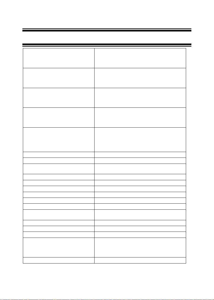
13 SPECIFICATIONS
Dissolved Oxygen
Range
Resolution
Relative accuracy
% Saturation of Oxygen
Range
Resolution
Relative accuracy
Temperature
Range
Resolution
Relative accuracy
Salinity Correction
Range
Resolution
Method
Barometric Pressure Correction (mm
Hg)
Range
Resolution
Method
Probe Galvanic
Response Time 40 seconds to achieve 93% of the reading
No. of Calibration Points Single point at 100% in saturated air or air-
Data Logging 16
HOLD function Yes
Auto-Off function Selectable
Auto Off Time 20 minutes after last key press
Averaging/Stability function Selectable
Display Dual LCD
Power Requirements four 1.5 V AAA-sized batteries (included) or
Battery Life > 50 hours
Temperature Compensation Automatic from 0 to 50 °C
Operating Range 0 to 50 °C
Dimensions Meter: 19.1 cm (L) x 8.9 cm (W) x 4.5 cm (H)
Shipping weight 0.92 kg
0.00 – 20.00 mg/L or ppm
0.01 mg/L; 0.01 ppm
± 1.5% of Full Scale
0.0 – 200.0 %
0.1 %
± 1.5% of Full Scale
0.0 – 50.0 °C
0.1 °C
± 0.3 °C
0.0 – 50.0 ppt
0.1 ppt
Manual input and automatic correction
555 to 808 mm Hg or 74 to 108 kPA
1 mm Hg or 0.1 kPA
Manual input and automatic correction
saturated water
AC adapter 110 or 220 VAC to 9 VDC (optional)
Boxed: 23.3 cm (L) x 21.6 cm (W) x 7.0 cm (H)
Probe: 173 mm (L) x 32 mm (Diameter), with 3m cable
51
Page 56
Instruction Manual DO 100
14 ACCESSORIES
Replacements and accessories
Eutech Instruments
DO 100 Hand-held Dissolved Oxygen Meter complete with one Submersible
Dissolved Oxygen probe with 3-meter (10-ft) cable (EC-DOHANDYNEW), one
assembled membrane cap housing (15X241402) and one 50ml electrolyte
(01X211226).
Submersible Dissolved Oxygen probe with 3-meter (10-ft) cable. EC-DOHANDYNEW
AC / DC Power Adapter (120 VAC / 9 VDC) EC-120-ADA
AC / DC Power Adapter (220 VAC / 9 VDC) EC-220-ADA
Hard carrying case for meter EC-WPDRYKIT
Soft carrying pouch for meter EC-POUCH-02
Membrane installation tool 15X241502
Membrane & O-ring (pack of 5) 01X241603
Replacement Membrane Housing Cap with Membrane and O-ring pre-installed 15X241402
Electrode Guard Removal Tool 15X241504
DO Refilling Electrolyte (50ml) 01X211226
Item Eutech Instruments
Ordering Code
EC-DO100/01
52
Page 57

Instruction Manual DO 100
Oakton Instruments
Item Oakton Instruments
Ordering Code
DO 100 Hand-held Dissolved Oxygen Meter complete with one Submersible
Dissolved Oxygen probe with 3-meter (10-ft) cable (EC-DOHANDYNEW), one
assembled membrane cap housing (15X241402) and one 50ml electrolyte
(01X211226).
Replacement submersible Dissolved Oxygen probe with 3-meter (10-ft) cable. 35640-50
Submersible DO probe with 25-ft cable 35640-52
Submersible DO probe with 50-ft cable 35640-54
Submersible DO probe with 100-ft cable 35615-56
AC / DC Power Adapter (120 VAC / 9 VDC) 35615-07
AC / DC Power Adapter (220 VAC / 9 VDC) 35615-08
Hard carrying case for meter 35632-98
Soft carrying pouch for meter 35615-75
Replacement membrane assembly with membrane lock, O-ring and cap. 35640-72
Replacement HDPE membranes, pack of 5. 35640-74
Replacement HDPE membranes, pack of 25. 35640-75
Membrane installation tool 35640-79
DO kit includes hard carrying case, and 35640-80 membrane kit (meter not
included).
Replacement membrane housing kit comes with two membrane housings with
pre-installed membrane and a bottle of premixed electrolyte.
35640-00
35640-60
35640-80
Solutions
Item Oakton Instruments
Ordering Code.
Zero oxygen solution, 500 mL 00653-00
Premixed electrolyte solution, 500 mL 35640-71
Electrolyte power (58.5 g) 35640-70
53
Page 58

Instruction Manual DO 100
15 WARRANTY
This meter is supplied with a three -year warranty, six-month warranty for probe agai nst signific ant
deviations in material and workmanship.
If repair or adjustment is necessary and has not been the result of abuse or misuse within the
designated period, please return – freight pre-paid – and correction will be made without charge.
Eutech Instruments/ Oakton Instruments will determine if the product problem is due to deviations or
customer misuse.
Out of warranty products will be repaired on a charged basis.
Exclusions
The warranty on your instrument shall not apply to defects resulting from:
• Improper or inadequate maintenance by customer
• Unauthorised modification or misuse
• Operation outside of the environment specifications of the products
16 RETURN OF ITEMS
Authorisation must be obtained from our Customer Service Department or authorised distributor
before returning items for any reason. A “Return Goods Authorisation” (RGA) form is available
through our authorised distributor. Please include data regarding the reason the items are to be
returned. For your protection, items must be carefully packed to prevent damage in shipment and
insured against possible damage or loss. Eutech Instruments/ Oakton Instruments will not be
responsible for damage resulting from careless or insufficient packing. A restocking charge will be
made on all unauthorised returns.
NOTE: Eutech Instruments Pte Ltd/ Oakton Instruments reserves the right to make improvements
in design, construction, and appearance of pr oducts without notice.
54
Page 59

Page 60

For more information on Eutech Instruments/ Oakton Instruments’ products, contact
your nearest distributor or visit our website listed below:
Oakton Instruments
P.O Box 5136,
Vernon Hills, IL 60061, USA
Tel: (1) 888-462-5866
Fax: (1) 847-247-2984
E-mail: info@4oakton.com
Web-sites:
www.4oakton.com
www.oaktoninstruments.com
Eutech Instruments Pte Ltd.
Blk 55, Ayer Rajah Crescent,
#04-16/24 Singapore 13 9949
Tel: (65) 6778 6876
Fax: (65) 6773 0836
E-mail: marketing@eutechinst.com
Web-site: www.eutechinst.com
Distributed by:
 Loading...