

Page 1
Instruction Manual
CyberScan CON 10/100/200
Hand-held Conductivity/TDS/Temperature Meter
68X075513
09/2001 Rev 3
Technology Made Easy ...
Page 2

Preface
This manual serves to explain the use of the CyberScan series Conductivity meters. The
models covered are the CyberScan CON 10, CyberScan CON 100 and CyberScan CON 200
portable conductivity and total dissolved solids meters.
This manual functions in two ways: first, as a step by step guide to help the user operate the
meter; second, it serves as a handy reference guide.
This manual is written to cover as many anticipated applications of the CyberScan
Conductivity meters as possible. If there are doubts in the use of the CyberScan Conductivity
meters, do not hesitate to contact the nearest Eutech Instruments Authorized Distributor.
Eutech Instruments cannot accept any responsibility for damage or malfunction to the meter
caused by improper use of the instrument. Remember to fill in the guarantee card and mail it
back to your authorized distributor or Eutech Instruments Pte Ltd.
The information presented in this manual is subjected to change without notice as
improvements are made, and does not represent a commitment on the part of Eutech
Instruments Pte Ltd.
Copyright © 1998 Eutech Instruments Pte Ltd. All rights reserved.
Revised in September 2001.
Page 3

TABLE OF CONTENTS
1 INTRODUCTION 1
2 DISPLAY AND KEYPAD FUNCTIONS 2
2.1 Display 2
2.2 Keypad 3
3 PREPARATION 5
3.1 Inserting the Batteries 5
3.2 Attaching the electrode holder onto the meter 7
3.3 Attaching the electrode onto the electrode holder 8
3.4 Connecting the A.C. adapter 8
3.5 Connecting the RS 232C cable (only for CyberScan CON 200) 9
4 CALIBRATION 12
4.1 Standard solutions for calibration 12
4.2 Preparing the meter for calibration 12
4.3 Calibration procedure 13
5 MEASUREMENT 19
5.1 Automatic Temperature Compensation 19
5.2 Manual Temperature Compensation 20
5.3 Taking measurements 21
6 MEMORY FUNCTIONS (IN CYBERSCAN CON 100 & 200 ONLY) 22
6.1 Data Input 22
6.2 Memory Recall 22
6.3 Memory Clear 23
7 PRINT FUNCTION (IN CYBERSCAN 200 ONLY) 24
7.1 Printing data 24
7.2 Printing errors 25
7.3 Sending data to the computer 25
7.4 Printing measurement data 25
7.5 Printing data from memory 25
8 SETTING UP THE CYBERSCAN (FOR CYBERSCAN CON 100/200 ONLY) 27
8.1 SETUP program 27
8.2 Program 1: Common functions 28
8.3 Program 2: Instruments Setup 30
8.4 Program 3: TDS Setup (in CyberScan CON 200 only) 33
8.5 Program 4: Communication Setup (in CyberScan CON 200 only) 35
9 CYBERCOMM POTRABLE - DATA ACQUISITION SOFTWARE (DAS FOR
CYBERSCAN CON 200 ONLY) 38
9.1 System Requirements 38
9.2 Loading CYBERCOMM PORTABLE 38
9.3 Running CyberComm Portable 44
9.4 Capturing And Printing Data Into Computer Using CyberComm Portable 48
9.5 Trouble-shooting Guide 49
10 TROUBLESHOOTING & ELECTRODE CARE 50
10.1 Troubleshooting 50
10.2 Electrode Care 52
11 ADDITIONAL INFORMATION 53
12 ACCESSORIES AND CALIBRATION BUFFER SOLUTIONS 55
12.1 Replacement Meter and Meter Accessories 55
12.2 Calibration Solutions 56
13 SPECIFICATIONS OF CYBERSCAN CON 10/100/200 57
14 WARRANTY & RETURN OF ITEMS 58
Page 4

1 INTRODUCTION
Thank you for selecting Eutech Instruments portable meter. This meter is a microprocessorbased instrument that is designed to be handy, user-friendly and capable of allowing one-hand
operation. It has a large customized LCD for clear and easy reading. It also has user-friendly
features, all of which are accessible through the membrane keypad. It is a unique and
intelligent instrument that has capability to cater to the preferences of the discerning individual.
You have one of three models:
•
CON 10 meter:
•
CON 100 meter:
•
CON 200 meter
Your meter includes a conductivity electrode (cell constant K = 1.0) with built-in temperature
sensor (Order Code: EC-CONSEN41B for CON 10, EC-CONSEN21B for CON 100/200), and
batteries. Please read this manual thoroughly before operating your meter.
1
Page 5
2 DISPLAY AND KEYPAD FUNCTIONS
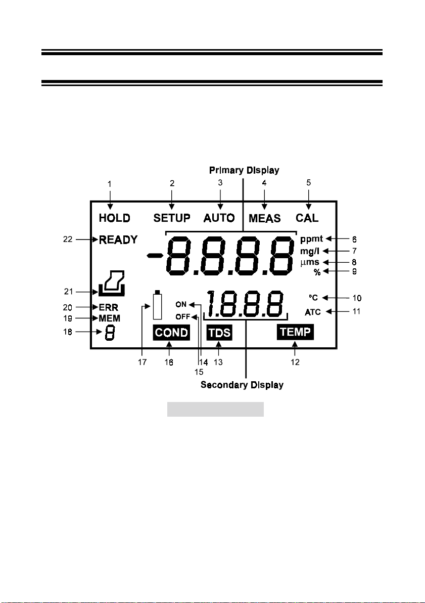
2.1 Display
The LCD has a primary and secondary display. The primary display shows the measured
conductivity or TDS reading. The secondary display shows the measured temperature. The
display also shows error messages, keypad functions and program functions. See Figure 1.
Figure 1: Full LCD Screen
1. HOLD indicator 9. Temperature coefficient in % 16. CONDuctivity mode indicator
2. SETup mode indicator 10. Temperature indicator 17. Low battery indicator
3. AUTO indicator 11. Automatic Temperature
4. MEASurement mode indicator 12. TEMPerature mode indicator 19. MEMory recall mode indicator
5. CALibration indicator 13. TDS mode indicator 20. ERRor indicator
6. parts per thousand or parts per million
indicator (for CON 10 & 200 meters
only)
7.milligrams per liter or grams per liter
indicator (for CON 10 & 200 meters
only)
8. microsiemens or millisiemens indicator
Compensation indicator
14. ON/OFF indicator - option is
turned on
15. ON/OFF indicator - option is
turned off
18. Index number of the memory
recalled or stored (except CON 10)
(except CON 10)
21. Printer indicator (for CON 200
only)
22. READY indicator
2
Page 6
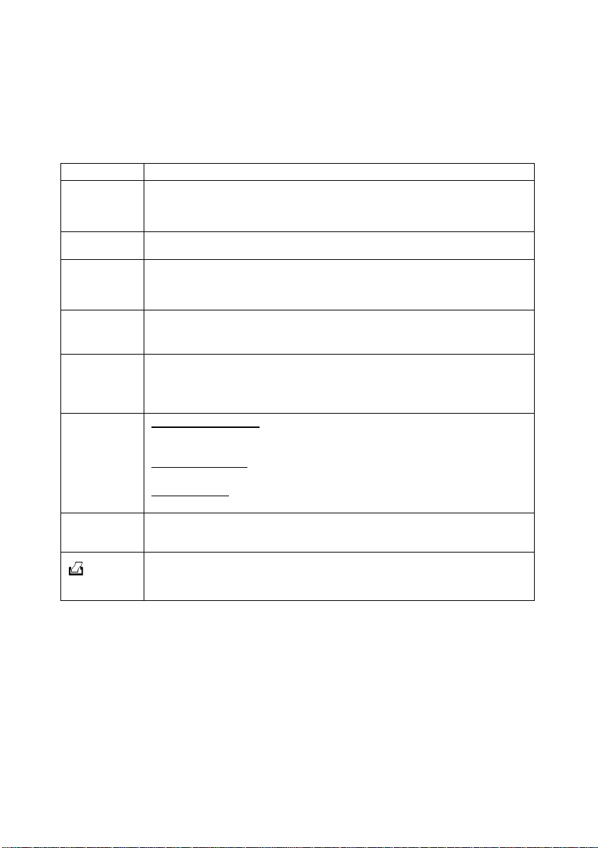
2.2 Keypad
The large membrane keypad makes the instrument easy to use. Each button, when pressed,
has a corresponding graphic indicator on the LCD. See Figure 2. Some buttons have several
functions depending on its mode of operation.
Key Function
Powers on and shuts off the meter. When you switch on the meter, the meter starts
ON/OFF
HOLD
MODE
CAL/MEAS
ENTER /
RANGE
MI/
& MR/
!!!!
(CyberScan CON
100/200)
&
!!!!
""""
(CyberScan CON
10)
SET
(CyberScan CON
100/200 only)
up in the mode that you last switched off from. For example, if you shut the meter off
in TDS measurement mode (only in CON 10 & CON 200 meters), the meter will be in
TDS measurement mode when you switch the meter on.
Freezes the measured reading. To activate, press HOLD while in measurement
mode. To release, press HOLD again.
Selects the measurement parameter.
CON 10 meter
~
CON 100 meter
~
CON 200 meter
~
Toggles between Calibration and Measurement mode.
NOTE
: Temperature calibration is available from conductivity calibration mode; see
section 4.3 for directions.
ENTER function:
selections in SETUP mode.
RANGE function:
The MEAS indicator blinks while in manual ranging function.
In Measurement mode:
""""
Press MI
in the memory. Press MR (memory recall) to retrieve data from memory.
In Calibration mode:
Press to scroll through calibration values.
In SETUP mode:
Press to scroll through the setup subgroup programs.
Takes you into the SETUP mode. This mode lets you customize meter preference
and defaults, and view calibration, electrode offset data and select cell constant.
: Toggles between conductivity, TDS and temperature.
: Toggles between conductivity and temperature.
: Toggles between conductivity, TDS and temperature.
Press to confirm values in Calibration mode and to confirm
Press to enter manual ranging function.
/
!!!!
(memory input) to store values with its corresponding temperature values
(CyberScan CON
200 only)
Sends the displayed data through the RS 232C connector to the peripheral device
(computer or printer).
3
Page 7
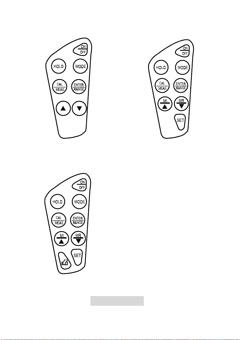
CyberScan CON 10 CyberScan CON 100
CyberScan CON 200
Figure 2: Keypad
4
Page 8
3 PREPARATION
3.1 Inse rting the Batteries
Four AAA batteries are included with your meter.
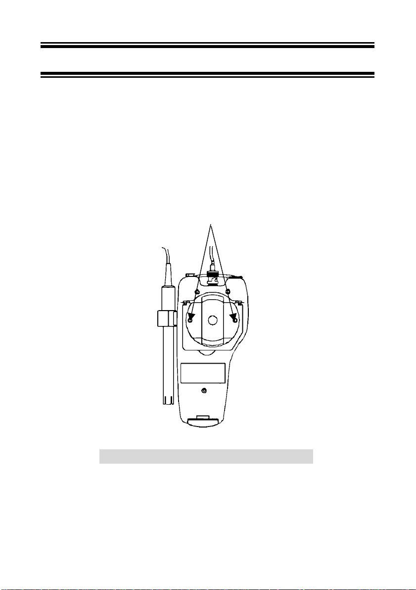
1. Use a Philips screwdriver to remove the two screws holding the battery cover. See Figure
3 below.
2. Lift meter stand to expose battery cover. Remove battery cover.
3. Insert batteries. Follow the diagram inside the cover for correct polarity.
4. Replace the battery cover into its original position using the two screws removed earlier.
Remove Screws
Figure 3: Back panel of meter showing battery compartment
5
Page 9
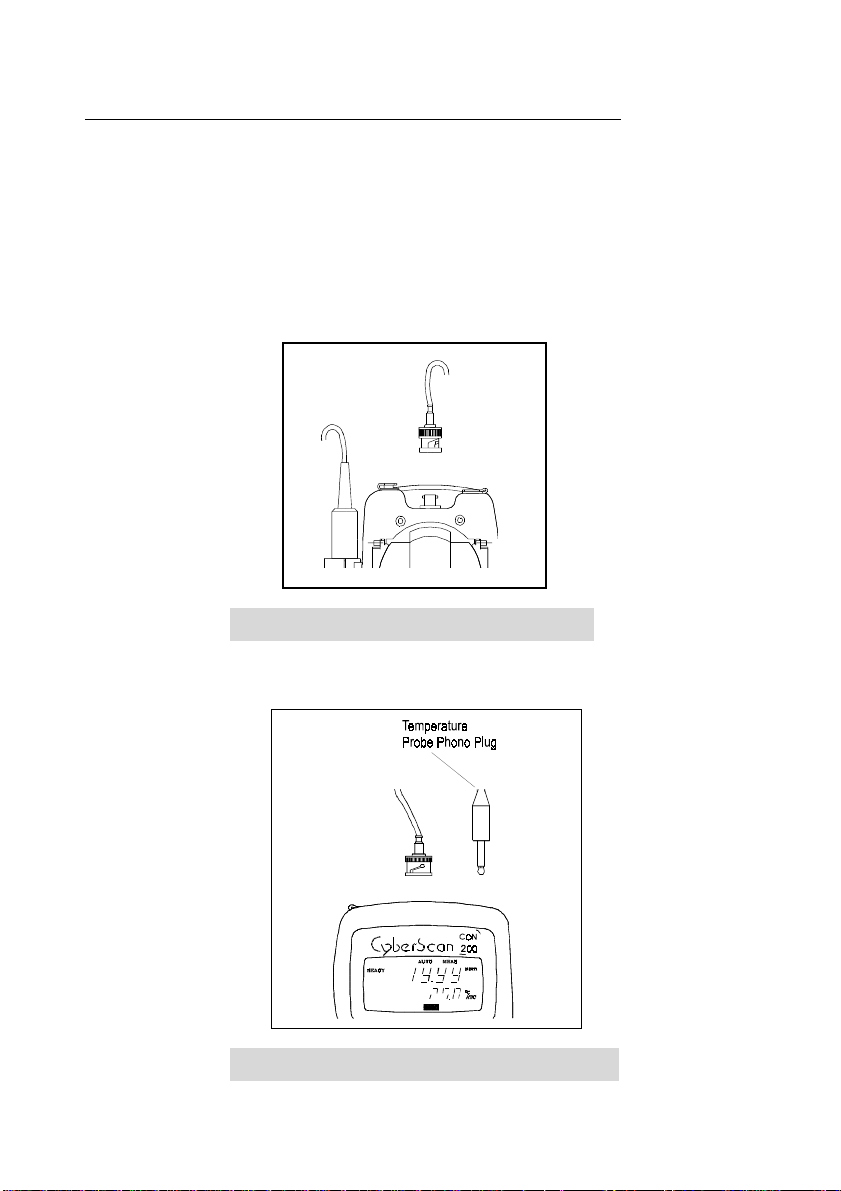
To connect the Conductivity/TDS electrode with built-in temperature sensor:
a) During this operation, it is important that water does not get onto the BNC connector.
Also avoid touching the connector with soiled hands.
Slide the electrode connector of electrode over the socket of the meter (BNC connector).
Ensure that the slot of the connector is inline with the protrusions of the socket.
Rotate the connector clockwise until it locks. Be careful not to use excessive force in this
operation.
Figure 4: Connecting the Conductivity /TDS probe
b) The built-in temperature probe uses a phono jack to connect with the socket on the
meter. Insert the jack into the socket as shown in Figure 5.
Figure 5: Connecting the built-in temperature sensor
6
Page 10
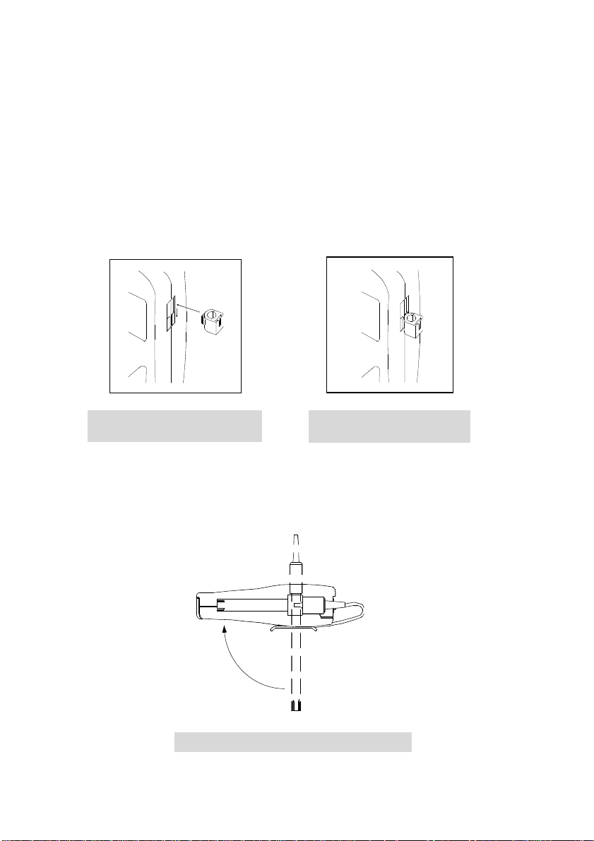
3.2 Attaching the electrode holder onto the meter
The meter has a slot on the side for the attachment of the electrode via the electrode holder.
a) The meter provides a slot on the side of the instrument for the electrode holder. Hold the
electrode holder over the slot of the meter. Ensure the flange of the electrode holder is
facing the slot. Note the orientation to make sure that it is the orientation that you desire
(see figure below).
b) Gently slide the flange of the electrode holder into the slot. Ensure that the electrode
holder is fixed properly into the slot.
Figure 6: Attaching the electrode
holder to the meter
Figure 7: Sliding the electrode
holder into the slot
3.2.1 Special Features
The electrode holder can be attached in different positions (multi-position) as shown. This
allows you the flexibility in measurement and storage.
Figure 8: Multi-position of the electrode holder
7
Page 11

3.3 Atta ching the electrode onto the electrod e holder
Your meter comes complete with an electrode holder. It is designed for easy use and
installation. Care must always be taken to avoid use of excessive force in the process of
attaching these components.
a) Align the end of the electrode (sensor side) with the hole of the holder. Note that the top
side of the holder is where the slot begins.
b) Always ensure that the diameter of the electrode you intend to use is 12 mm. Otherwise,
the electrode may not fit properly.
c) Insert the electrode into the hole of the holder until the top housing of electrode touches
the top of the holder. Remember not to force the electrode into the holder.
3.4 Connecting the A.C. adapt er
The CyberScan CON 10/100/200 meter has the flexibility of operating from an A.C. powe r
source. This is extremely useful if you have an A.C. source available near the meter (e.g.
Laboratory).
1. Before plugging in the A.C. adapter, switch off the meter and the po wer source of the
A.C. adapter. This is a safety precaution that should be adhered to safeguard your meter.
2. The A.C. adapter should have the following settings:
Output Voltage: 9 V D.C.
Current: 500 mA
NOTE: Ensure that the input mains voltage (110/220/240 V) matches your adapter
requirements.
3. Insert the D.C. jack into the socket of the meter as shown in Figure 9.
4. Switch on the power to the adapter, followed by the meter.
8
Page 12
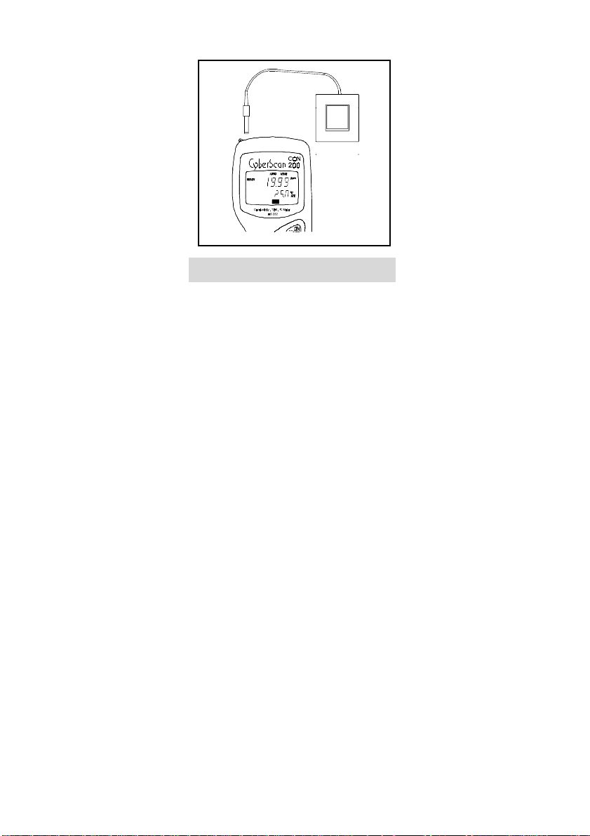
Figure 9: Inserting the A.C. power adapter
3.5 Connecting the RS 232C cable (only for CyberScan CON 200)
The CyberScan Conductivity CON 200 meter provides an RS 232C output for you to transmit
the reading either to a printer or a computer. This is extremely useful in instances where the
meter is used for continuous monitoring of a certain process or experiment. The data output to
the printer or computer can be then evaluated.
The data is output in the ASCII format. This format allows the data to be imported by a wide
variety of software that read ASCII data (e.g. LOTUS 123 C, Microsoft Excel, etc.).
Eutech Instruments also provides software that can capture the data transmitted into an ASCII
file for later use.
a) Open the communication port cover located at the bottom of the meter as shown in
Figure 10. Do not use excessive force when doing this.
b) Noting the orientation of the RS 232C connector, plug the RS 232C male connector into
the RS 232C port of the meter.
c) Fasten the connector by fastening the two screws at the side of the male connector.
9
Page 13
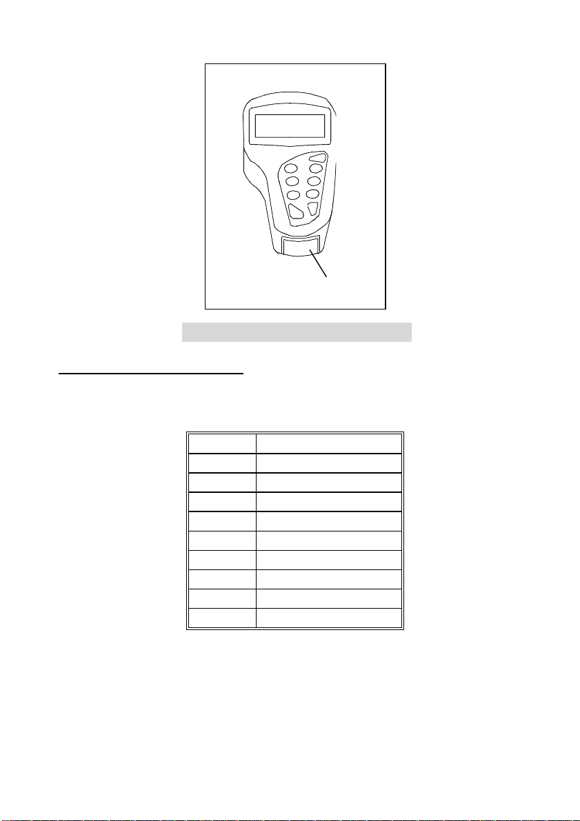
Location of
RS 232 port
Figure 10: The CyberScan CON 200 RS 232 port
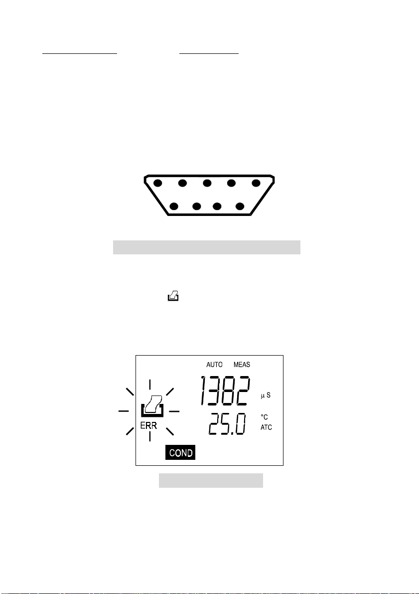
3.5.1 RS 232C Configuration
The CyberScan CON 200 meter has a 9-pin female RS 232C connector with the following pinout:
PIN NO DESCRIPTION
12 Transmit Data
34 DSR (Data Set Ready)
5GND
67 CTS (Clear to Send)
89-
A one-is-to-one connection can be made with a 9-pin RS 232C port of the computer.
In case the meter output has to be sent to a 25-pin RS 232C connector, the following cable
configuration may be used:
10
Page 14
CyberScan CON 200 25-pin connector
g
2 (TxD) --------------------------------------- (RxD) 3
4 (DSR) -------------------------------------- (DTR) 20
5 (GND) -------------------------------------- (GND) 7
7 (CTS) --------------------------------------- (RTS) 4
Refer to Figure 11 for the pin number position.
5432 1
987 6
Figure 11: Pin number position of the 9-pin RS 232 port
The meter uses hardware handshake i.e. the meter expects both DSR and CTS lines to be
active before it sends data. If the
key is pressed while the printer is not ready or if the
printer is off, the meter displays error by blinking the printer and the ERR annunciators
alternately, and waits for the printer to be ready. While the meter is displaying printer error, the
user may press the CAL/MEAS key to return to the measurement (MEAS) mode.
Figure 12: Error in printin
11
Page 15

4 CALIBRATION
4.1 Stand ard solutions for calibrat ion
Select conductivity or TDS calibration solution (available from the distributor) which is close to
the expected conductivity of the sample that you want to measure. Ensure that the calibration
solution which you use comes with a “Temperature vs Conductivity” or a “Temperature vs
TDS” label on it. This information is required during calibration.
NOTE: Eutech’s calibration solutions are supplied in shatterproof bottles of 480 ml. Refer to
section 12 for Ordering Information and details for other accessories.
In CON 100 meter, calibration is only done in the conductivity (COND) mode. The CON 10
and CON 200 meters allow calibration either in the conductivity range or the TDS range but
not both. As such, a calibration in the TDS mode of a particular range will replace a prior
calibration in the conductivity mode if both ranges are the same (i.e. Range 2 in COND and
Range 2 in TDS).
In general, it is recommended that calibration be performed around a point close to 2/3 of f ull
scale. For better accuracy, perform a calibration close to the expected measurement range
prior to the measurement.
Corresponding TDS values are obtained by multiplying the recommended conductivity values
by the TDS factor. The default TDS factor is 0.5.
4.2 Prep aring the meter for calibration
Before starting calibration, make sure you are in the correct measurement mode. When you
switch on the meter, the meter starts up in the measurement mode you shut it off in previously.
For example, if you shut the meter off in COND measurement previously, the meter will come
back into COND measurement when you switch the meter on.
Before calibrating, select the correct mode by pressing the MODE key. There are 3 modes:
COND for conductivity measurements,
TDS for total dissolved solids (TDS) measurements,
TEMP for temperature measurements.
12
Page 16
4.3 Calibration procedure
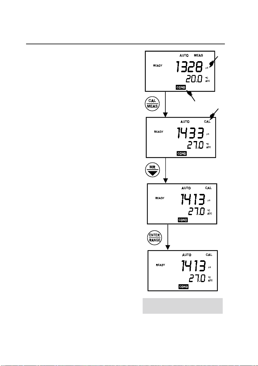
4.3.1 Procedure for conductivity calibration (CyberScan CON 10/100/200)
1. If necessary, press the MODE key to select
COND mode. The µs indicator appears in the
upper right hand corner of the display.
2. Rinse the probe thoroughly with de-ionized
water or a rinse solution.
3.
Dip the probe into the buffer solution. The
end of the probe must be completely
immersed into the buffer solution. Stir the
probe gently to create a homogeneous
sample. Agitate the probe in the solution to
dislodge air bubbles that are trapped in the
probe.
4. Press the CAL/MEAS key to enter the COND
calibration mode. The CAL indicator will be
shown. The primary display will show the
measured reading.
5. Use the ! or " key for CON 10, or MI/! or
MR/" key for CON 100/200, to adjust the
measured value to that of the standard
solution.
6. Wait for the measured conductivity value to
stabilize. See Figure 13 for the conductivity
calibration procedure.
NOTE: To exit without confirming the
calibration, press the CAL/MEAS key.
For calibration in the other ranges (maximum:
5 ranges, repeat steps of the procedure, this
time using a solution with a conductivity of a
different range).
13
Figure 13: Conductivity calibration
procedure
Page 17

4.3.2 Procedure for TDS calibration (CyberScan CON 10/200 only)
Two methods are available for TDS calibration. The first method (Method 1) applies to both
CyberScan CON 10 and 200 meters. Method 1 relies on the availability of a table that shows
the TDS values of the TDS calibration buffer solution at various temperatures. The second
method (Method 2) relies on the availability of conductivity-to-TDS conversion factors at
standard temperature such as at 25 °C. Method 2 applies only to CyberScan CON 200 meter.
The advantage of Method 1 is that it is simpler to perform than Method 2. However, one
should note that much of calibration buffer solutions do not reference the TDS values at
temperatures other than 25 °C, and that without the use of proper conductivity-to-TDS
conversion factor, this calibration may not be as accurate over a wider range of measurement.
Also, in some cases, the meter may not accept the TDS value input into it giving an error
message because the calibration value exceeds the allowable slope adjustment limits of the
meter when using a default conductivity-to-TDS conversion factor such as 0.50.
Method 2 overcomes the shortcomings of Method 1 by ensuring the TDS measurement
accuracy over a broader range of TDS measurements around the calibration value. The meter
will virtually accept any TDS calibration input from virtually any commonly used TDS
calibration buffer solution. The only requirement is that the buffer solution indicates the TDS at
a standard temperature such as 25 °C.
NOTE: It is important to have knowledge of the conductivity-to-TDS conversion factor or the
factor can be calculated using the formula below:
Factor =
TDS
Conductivity
14
@ 25°C
Page 18
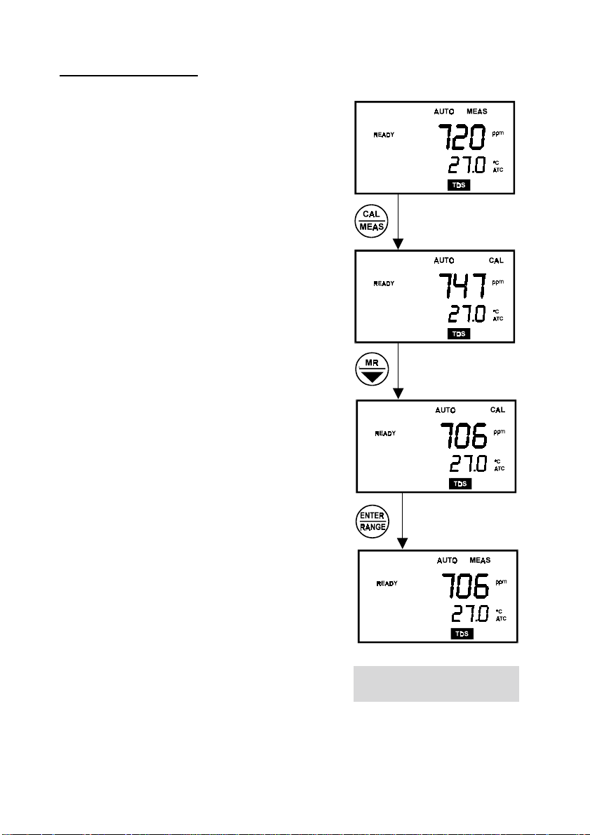
TDS calibration: Method 1
1. Select the TDS standard solution with a value that
is closest to the measurements expected in the
sample (in this manual, the KCI standard solution
1413 µS is about 706.5 ppm).
Check this number by multiplying the conductivity
reading by the factor and the result should be the
TDS in equivalent units.
2. First, pour enough of the selected sample into two
separate clean containers so as to allow the
probe to be immersed up to the bleed hole.
3. Rinse the end of the probe into one of the
containers by gently stirring it in the standard
solution. This helps remove contaminants that
offset the calibration and introduce error.
4. Dip the rinsed probe into the other container
containing the unused solution.
5. Allow the probe some time to stabilize to the
solution temperature.
6. Select the TDS mode using the MODE key. Note
the temperature of the calibration solution and
find the corresponding TDS value of the
calibrating solution at that temperature.
For example, the meter displays the temperature
of 27 °C, and a TDS value of 720 ppm (when
normalized to 25 °C) with the uncompensated
value at 27 °C should be 733 ppm.
7. Upon pressing the CAL/MEAS key, the CAL
annunciator on the screen will blink, indicating the
calibration mode is on. The LCD displays the
uncompensated TDS value.
15
Figure 14: TDS calibration
procedure Method 1
Page 19

8. Use the ! or " key for CyberScan CON 10, or MI/! or MR/" key for CyberScan 200 to
scroll up or down respectively to the value of the standard solution at 25 °C.
9. Press the ENTER/RANGE key to confirm the calibration. The CAL indicator will stop
flashing and remains on the screen for 3 seconds. Then the meter switches back into the
measurement mode and the calibrated value, compensated to the current temperature, is
shown on the display.
The display will now show 706 ppm that is the correct value of the standard solution at 27
°
C. Measurements can be performed now.
10. To exit from this process without confirming the calibration, press the CAL/MEAS key.
For calibration in the other ranges (maximum: 5 ranges for CON 200 only) repeat steps of the
procedure as outlined in Method 1, this time using a solution with a TDS of a different range.
Error upon confirmation
If an ERR error message appears, it probably means that the meter does not allow the slope
adjustment that has been made via the calibration procedure given the value of the
conductivity-to-TDS conversion factor currently in the memory.
If you are using CyberScan CON 200 meter, consider Method 2 of the TDS calibration. Press
the CAL/MEAS key to escape the ERR message and abort the calibration attempt.
Inaccuracies after calibration
If the TDS value is not within 2 digits of the TDS standard solution value at 25 °C or 20 °C
(depending upon which value was selected in the SETUP), an adjustment of either of the
following is required.
•
Temperature coefficient
•
Calibration
•
Conductivity-to-TDS conversion factor (see Method 2)
16
Page 20

TDS calibration: Method 2 (for CyberScan CON 200 only)
1. Select the TDS standard solution with a value
that is closest to the measurements expected in
the sample (in this manual, the KCI standard
solution 1413 µS is about 706.5 ppm at 25 °C).
2. Pour about 3 cm of the selected sample into two
separate clean containers.
3. Rinse the end of the probe into one of the
containers by gently stirring it in the standard
solution. This helps remove contaminants that
offset the calibration and introduce error.
4. Dip the rinsed probe into the other container
containing the unused buffer solution.
5. If the Eutech standard solution is used, the correct
Conductivity-to-TDS conversion factors are given
for KCI, NaCI & 442 natural water formulation at
25 °C under the “Multiply By:” on the label. If
another brand of TDS calibration is used, refer to
the formula:
Press ENTER key
repeatedly until you
come to P3.0.
Factor =
Select the correct factor according to the protocol
of the method, or that is closest to the solution to
be measured.
6. Enter into the SETUP mode by pressing the SET
key (note that this mode can be entered only from
the MEAS mode).
Press the ENTER/RANGE key repeatedly until Program 3.0 (TDS factor) is shown.
TDS
Conductivity
@ 25 °C
17
Figure 15: TDS calibration
procedure Method 2
Page 21

7. Using the MI/! or MR/" key, adjust the value of the primary display until it is the same
or close to the selected/calculated value.
Confirm the selected value by pressing the ENTER/RANGE key.
8. Exit the SETUP mode and return to the MEAS mode by pressing the CAL/MEAS key
upon completion of step 7. Press the MODE key until the TDS mode is entered. The TDS
value will be the buffer solution value for the type of TDS solution selected. The value will
also be temperature compensated and the conductivity-to-TDS conversion input will
ensure greater accuracy over a broader range of TDS curves used.
18
Page 22

5 MEASUREMENT
This meter is capable of taking measurements with automatic or manual temperature
compensation. Automatic temperature compensation only occurs when a temperature sensor
is plugged into the meter. If there is no temperature sensor plugged into the meter, the default
manual temperature setting is automatically 25 °C. You can manually set the temperature to
match your working conditions using a separate thermometer.
5.1 Auto matic Temperature Compensation
For automatic temperature compensation (ATC) simply plug the built-in temperature sensor
probe into the meter. The ATC indicator will light up on the LCD (see figure 16).
Figure 16: Automatic Temperature Compensation
(ATC) indicator
19
Page 23

5.2 Manual Temperature Compensation
IMPORTANT: For manual compensation, you must disconnect the temperature probe. The
ATC annunciator will disappear from the LCD.
1. Press the MODE key to select TEMP mode.
2. Press the CAL/MEAS key to enter
Temperature calibration mode. The CAL
indicator will appear above the primary
display.
3. The primary display shows the current
conductivity/TDS reading and the
secondary display shows the default
temperature value 25 °C.
4. Check the temperature of your sample
using an accurate thermometer.
5. Press the ! or ", or MI/! or MR/" key to
set the temperature to the measured value
obtained in step 4. To confirm, press
ENTER/RANGE key.
6. Press the CAL/MEAS key to exit and return
to conductivity measurement mode.
NOTE: To exit this program without confirming
the manual temperature compensation value, DO
NOT press ENTER/RANGE in step 5. Press
CAL/MEAS instead.
20
Figure 17: Setting the Temperature
Compensation manually
Page 24

5.3 Taking measurements
To take readings
1. Rinse the probe with de-ionized or distilled water before use to remove any impurities
adhering to the probe body.
2. Press ON/OFF key to switch on the meter. The MEAS annunciator appears on the top
center of the LCD. The ATC indicator appears in the lower right-hand corne r to indicate
Automatic Temperature Compensation.
3. Dip the probe into the sample.
4. When dipping the probe into the sample, the sensor of the electrode must be completely
immersed into the sample. Stir the probe gently in the sample to create a homogeneous
sample. Agitate the probe in the sample to dislodge air bubbles that are trapped in the
probe.
5. Allow time for reading to stabilize. Note the reading on the display.
21
Page 25

6 MEMORY FUNCTIONS (IN CYBERSCAN CON 100 &
200 ONLY)
6.1 Data Input
Press the MI/! key in the measurement (MEAS) mode, to input any data into the memory.
The meter will automatically store the displayed data into the memory.
Model Parameters
CON 100 Conductivity & temperature
CON 200 Conductivity & temperature and/or TDS & temperature
A total of 16 sets of data can be stored into the memory of the meter. The memory stored is
identified by the memory number (in hexadecimal numbering format, i.e. from 0 to 9 followed
by A to F) as displayed at the bottom left corner of the screen. The Last-In-First-Out (LIFO)
method of memory management is used. See section 7.5 (Printing data from Memory) for
illustration.
If the memory is full, the first memory contents (i.e. memory #1) will be erased. Memory #2 is
reassigned #1 and so on, leaving the last space #F free to receive the latest input.
To store the value of the measurement into the
memory of the meter, press the MI/! button. This
will store both the parameter (conductivity or TDS)
and the temperature into the memory. The MEM
annunciator will be displayed briefly to indicate that
the data has already been stored into memory. The
memory number indicator, at the bottom left hand
corner, will flash the number of memory stored.
Figure 18: Data input to the
memory
6.2 Memory Recall
Memory recall is invoked to recall the data sets
stored in memory. Memory recall is activated in the
following sequence:
22
Figure 19: Memory Recall
Page 26

1. Press the MR/" once to recall the last data set.
NOTE: Memory Recall (MR) is only accessible in the MEAS mode. Press CAL/MEAS key
to return to the measurement mode.
2. Press the MR/" key again to recall the next latest data set stored.
NOTE: Memory data is retained even if the power of the unit is switched off (even with
the batteries removed). Memory is erased when using Program 1.0 of SETUP (see
section 8.2.1).
6.3 Memory Clear
Under normal operating conditions, fresh data sets will automatically be stored at the expense
of data sets stored earlier. The instrument holds up to a maximum of 16 sets of data. The
meter also has a feature that enables easy but safe clearing of memory facilities. The process
to be followed in clearing the memory is outlined in SETUP (see section 8.2.1). The
accessibility of this function through the SETUP mode is to limit accidental clearing of memory
from the measurement mode.
23
Page 27

7 PRINT FUNCTION (IN CYBERSCAN 200 ONLY)
7.1 Printing data
The CyberScan CON 200 meter is equipped with a key that facilitates the printing of data
into the computer in the form of a data file.
Using the CyberScan CON 200 meter with the printer
1. To use the CyberScan CON 200 meter directly with a printer, the printer should have
either a 9-pin or a 25-pin RS 232 serial port.
2. Printer dip switches should match with the meter communication setup. The printer
should have options to receive 8 data bits, even (2), odd (1) or none (0) parity bit and one
(1) or two (2) stop bits. These parameters are standard printer options.
3. Use the cable provided to connect the meter to the printer. If the printer has a 25-pin
connector, use a 9 to 25-pin converter (if available) or make your own cable taking note
of the connection parameters as described in Section 3.5 (Connecting the RS 232 cable).
4. Set the dip switch of the printer to accept serial data. This is required if the printer has
both serial and parallel interfaces. Set the dip switch to accept 8 data bits.
5. Switch on the meter.
6. Change the CON 200 meter setup parameters for the proper baud rate, parity and stop
bits. Ensure that these parameters are identically set on both the printer and the meter.
7. Insert the paper and switch the printer on.
8. To send data to the printer, press the
key.
24
Page 28

7.2 Printing errors
The meter displays an error by blinking the printer
and error annunciators if the printer is not ready to
receive data or if the printer is off. As soon as the
printer is ready, the error display will automatically go
off. While the meter is displaying the printer error, the
user may press the CAL/MEAS key to go back to the
measurement mode.
7.3 Sending d ata to the computer
To send data to the computer, connect the RS 232C
cable from the base of the meter to the COMM port 1
of the computer. Load and run the CYDATA data
acquisition program ensuring that the parameters of
the settings in the meter and the CYDATA are
identical.
Figure 20: Display of printing
error
To send data to the computer, press the
key.
Figure 21: Sending data to the
computer
7.4 Printing measurement data
To print any data that is currently being measured, press the key. Note that the printing
capability is available for the COND, TDS and TEMP modes.
The data will be printed onto the printer paper or the screen of the CYDATA program
automatically as illustrated in Page 26.
7.5 Print ing data from memory
The CyberScan CON 200 meter can print data that is stored in the memory. Firstly, ensure
that the cables are properly connected to either the printer or the computer and the units are
configured to receive the data from the meter.
Change the mode to the mode of measurement from
which data needs to be printed.
Scroll to the data that needs to be printed by pressing
the MR/" key. To print, press the
displayed will then be sent to the printer or the computer.
An example of the printout is shown in Page 26.
key. The data
Figure 22: Printing data from
memory
25
Page 29

An example of a printout for Printing Measurement Data:
Cond: 1.00 mS Temp: 33.2 Date: 07-30-96 Time: 14 : 00 : 09
Cond: 100 uS Temp: 33.2 Date: 07-30-96 Time: 14 : 00 : 11
Cond: 10.0 uS Temp: 33.2 Date: 07-30-96 Time: 14 : 00 : 14
Cond: 1.00 uS Temp: 33.2 Date: 07-30-96 Time: 14 : 00 : 24
Cond: 199.9 uS Temp: 33.2 Date: 07-30-96 Time: 14 : 00 : 28
Cond: 1999 uS Temp: 33.2 Date: 07-30-96 Time: 14 : 00 : 30
Cond: 19.99 uS Temp: 33.2 Date: 07-30-96 Time: 14 : 00 : 32
Cond: 199.9 uS Temp: 33.2 Date: 07-30-96 Time: 14 : 00 : 34
TDS: 0.00 ppm Temp: 33.2 Date: 07-30-96 Time: 14 : 00 : 59
TDS: 0.64 ppm Temp: 33.2 Date: 07-30-96 Time: 14 : 01 : 32
TDS: 10.0 ppm Temp: 33.2 Date: 07-30-96 Time: 14 : 01 : 38
TDS: 10.0 ppm Temp: 33.2 Date: 07-30-96 Time: 14 : 01 : 40
TDS: 0.00 ppt Temp: 33.2 Date: 07-30-96 Time: 14 : 01 : 59
TDS: 0.00 ppt Temp: 33.2 Date: 07-30-96 Time: 14 : 02 : 02
TDS: 1.05 ppm Temp: 33.2 Date: 07-30-96 Time: 14 : 01 : 06
An example of a printout for Printing Data from Memory
Mem: 7 Cond: 13.21 mS Temp: 25.0 Date: 07-30-96 Time: 14 : 00 : 52
Mem: 6 Cond: 199.9 mS Temp: 25.0 Date: 07-30-96 Time: 14 : 00 : 55
Mem: 5 Cond: 1999 uS Temp: 25.0 Date: 07-30-96 Time: 14 : 00 : 57
Mem: 4 Cond: 14.52 uS Temp: 25.0 Date: 07-30-96 Time: 14 : 00 : 59
Mem: 3 Cond: 14.52 uS Temp: 25.0 Date: 07-30-96 Time: 14 : 01 : 06
Mem: 2 T DS: 0.06 ppm Temp: 25.0 Date: 07-30-96 Time: 14 : 02 : 11
Mem: 1 T DS: 0.06 ppm Temp: 25.0 Date: 07-30-96 Time: 14 : 02 : 13
Mem: 0 T DS: 0.06 ppm Temp: 25.0 Date: 07-30-96 Time: 14 : 00 : 15
26
Page 30

8 SETTING UP THE CYBERSCAN (FOR CYBERSCAN
CON 100/200 ONLY)
8.1 SETUP program
In the SETUP mode in CyberScan CON 100/200 meter, there are four main programs. Each
has been divided into several options. The programs and options are elaborated under the
following sections:
PROGRAM DESCRIPITION SECTION
1 Common functions 8.2
2 Instruments setup 8.3
3 TDS units and factor 8.4
4
To enter the SETUP mode, press the SET key from either the µS or ppm measurement MEAS
mode. The meter automatically enters Program 1, Option 0 (P1.0). The meter prompts you
with the program numbers in the secondary field of the display.
NOTE: Entry to SETUP is only accessible from the MEAS mode.
Selection of the ENTER/RANGE key confirms selection of the options chosen. The instrument
then automatically scrolls to the next program. Within each program, you can use MI/! or
MR/" key to make appropriate selections. There are some options that permit the viewing of
data and are useful for diagnostic purposes.
Communication
parameters
8.5
Ensure that the ENTER/RANGE key is pressed to confirm your option in each program.
To exit from the program after the confirmation of choice or to abort from the SETUP mode,
press the CAL/MEAS key to return to the MEAS mode.
NOTE: You may press the CAL/MEAS key to exit SETUP mode at any time.
To exit SETUP
27
Page 31

8.2 Prog ram 1: Common functions
y
The following 3 options are commonly used:
8.2.1 P1.0: Memory Clear
16 sets of readings can be stored in the meter. Both
conductivity and temperature or TDS and temperature
readings are stored.
ON Clears all values stored in memory
OFF Memory values remain in storage
Activation of this option by selecting ON and confirmation of
memory clears all memory values. This is done by toggling
the annunciator to ON using the MI/! or MR/" key, and
pressing ENTER/RANGE to confirm the selection.
8.2.2 P1.1: %Temperature coefficient
adjustment
The amount of change in conductivity per degree centigrade
is referred to as the Temperature Coefficient, expressed in
%/°C at a particular temperature. The meter provides the
options of selecting the appropriate temperature coefficient,
from 0.0 to 10.0 %/°C, depending on the type of solution
measured.
The primary display indicates the temperature coefficient in
%/°C. You can use the MI/! or MR/" key to scroll to a
required value from 0.0 to 10.0 %/°C. Once you have made
your selection, press ENTER/RANGE key to confirm the
value.
The program will automatically scroll to the next SETUP
parameter. Under default condition, the temperature
coefficient is set to 2.0%/°C.
28
Figure 23: Memory clear displa
Figure 24: Temperature
coefficient adjustment setup
Page 32

8.2.3 P1.2: Calibration Status Display
y
The meter can be used to a maximum of five different calibrations in its five ranges of
measurement. This SETUP program not only allows you to see if a particular range has been
calibrated, but indicates the calibrated value. The secondary value shows P1.2. The range
number (i.e. 1, 2, 3, 4 & 5) is indicated in the left corner of the display. While in P1.2, you can
press MI/! or MR/" key which will scroll from range number 1 to 5 to display all the
calibration status of the five ranges shown in the primary display. On pressing ENTER/RANGE
key, the meter scrolls into the next SETUP parameter.
The meter will display the calibrated value in each range and the units (ppt/ppm/µS/mS)
depending upon which modes were used during calibration. This allows a greater ease of use.
NOTE: The meter stores a maximum of five calibration values per range i.e. one calibration
value per range. See Section 4 on Calibration. If the TDS factor (see Program 3.0) is changed,
all previous TDS calibration values will not have a meaningful relationship to physical
parameters and the meter displays “-- -- -- --“ for all TDS calibration values.
This indicates that the meter is not calibrated in any of the five ranges using the new TDS
factor.
NOTE: The previous calibration status would not be restored if the previous TDS factor were
re-entered.
It is, therefore, necessary to calibrate the meter once the TDS factor is changed. Then, the
SETUP mode will show the status of the five calibration ranges, indicating the TDS values in
which you have calibrated with the respective range numbers.
Figure 25: Calibration status displa
Otherwise, the meter will continue to function with the previous calibration values and the new
TDS factor, unless calibration is specifically reset by the SETUP option P2.2.
29
Page 33

8.3 Prog ram 2: Instruments Setup
8.3.1 P2.0: Ready selection
Activation of the READY option ensures that the READY
indicator is displayed when the electrode reading
stabilizes. READY options can be switched on or off by
pressing the MI/! or MR/" key as indicated by ON or
OFF in the display, followed by ENTER/RANGE key.
Under factory default, the option is ON.
READY annunciator appears when variation is
ON
within 1 LSD (Least Significant Digit)
OFF READY annunciator will not appear
8.3.2 P2.1: Auto-Off
To conserve the power, the meter has an AUTO-OFF
feature. Activation of the auto-off option will automatically
power off the instrument 20 minutes after the last key
selection. This feature is useful for conserving battery
power. If this feature is not required, it can be switched off
by using the MI/! or MR/" key, and pressing
ENTER/RANGE key.
Figure 26: READY option
Under default condition, the option is activated.
ON
Meter switches off automatically 20
minutes after the last key operation
Meter will operate continuously until
OFF
switched off manually using the
ON/OFF key
Figure 27: Auto-Off option
30
Page 34

8.3.3 P2.2: Calibration Reset
P2.2 provides the option to reset all user selectable
functions to the default settings. If you toggle the
annunciator to ON using the MI/! or MR/" key, and press
ENTER/RANGE key, all data will be reset.
RESET clears
all calibration data in memory (of both conductivity
and TDS)
. You need to power ON the instrument before
proceeding with any other functions.
Under default condition, RESET option is OFF.
NOTE: Data cannot be selectively deleted.
ON Reset all calibration points
OFF Reset off
8.3.4 P2.3: Temperature Normalization
The ATC (Automatic Temperature Compensation)
function automatically compensates for the variation
caused by temperature difference during measurement
and at the standard temperature (20 or 25 °C) and gives
the corrected read-out of the equivalent conductivity of
the solution. Hence, the conductivity/TDS can be
normalized to display the equivalent conductivity/TDS at
either 20 or 25 °C.
Figure 28: The RESET option
Normalization temperature can be selected between 20 &
25 °C using the MI/! or MR/" key. The primary display
shows normalization temperature. Pressing
ENTER/RANGE key registers the selected temperature at
which the conductivity/TDS value is normalized. Default is
at 25 °C.
31
Figure 29: The Temperature
Normalization option
Page 35

8.3.5 P2.4: Cell Constant Selection - 0.1 / 1.0 / 10.0
This option allows you to select the cell constant of the
electrode supplied has a nominal cell constant of 1.0. This
option is important to obtain optimal readings in the various
ranges of measurement. A table is shown below for K value
selection of electrodes.
Ranges available K=0.1 K=1.0 K=10.0
0.00 -19.99 µS**
0.0 -199.9 µS**
0 - 1999 µ S*
0.00 - 19.99 mS * *
0.0 - 199.9 mS * *
In Program 2.4, use the MI/! or MR/" key to select the
required cell constant and confirm by pressing
ENTER/RANGE. The display then shows the selected cell
constant.
Figure 30: The cell constant selection
32
Page 36

8.4 Prog ram 3: TDS Setup (in CyberScan CON 200 on ly)
p
8.4.1 P3.0 TDS factor
The TDS factor for a particular standard solution is a
multiplication factor which relates the measurement of
conductivity in µS/cm to its equivalent reading in
ppm/mg/l. This factor is unique for each solution.
This option allows the selection of the TDS factor for the
solution to be measured. The TDS factor is shown on the
primary display. Toggle the MI/! or MR/" key to select
the exact TDS factor. The range of values is from 0.4 to
1.0. Any values less than 0.4 or more than 1.0 would
cause an error. Press the ENTER/RANGE key to confirm
the TDS factor selected. Under default conditions, the
TDS factor is set to 0.5.
Figure 31: The TDS setu
33
Page 37

8.4.2 P3.1: TDS units
In default, the meter shows TDS measurement unit in
ppm. To select the TDS measurement in mg/l, toggle the
TDS units using the MI/! or MR/" key. Press enter key
to confirm the selection, and the meter scrolls into P4.0.
Figure 32: Selecting the TDS unit
34
Page 38

8.5 Prog ram 4: Communication Setup ( in CyberScan CON 200
only)
This program allows you to set up the instrument’s communication parameters of the
CyberScan CON 200 meter to enable proper communication with the printer or computer of
choice.
8.5.1 P4.0: Baud Rate
You can select a baud rate of 2.4, 4.8, 9.6 or 19.2 kbps
(kilo bits per second). Under default conditions, the baud
rate is set to 9.6 kbps (9600 bps).
1. From COND or TDS measurement mode, press
SET key.
2. Press ENTER/RANGE key until P4.0.
3. Use the MI/! or MR/" key to change different baud
rate.
4. Press ENTER/RANGE key to confirm and continue
to set Parity in P4.1.
See figure 33.
Figure 33: The Baud Rate option
35
Page 39

8.5.2 P4.1: Parity
Parity check allows the receiving unit to monitor the
integrity of the data that the meter transmits. To
accommodate for the variances in standards used, three
different parity checks have been provided. They are as
shown in the table below. The default parity is even (2).
Value Parity
0 No parity
1 Odd parity
2 even parity
Figure 34: The Parity Check option
36
Page 40

8.5.3 P4.2: Stop Bit
The Stop Bit allows the selection of the proper stop bit when transmitting to other pe ripheral
devices (such as printers). You can select the stop bit to be 1 or 2 depending upon the model
and make of the peripheral device (the instruction manual of the peripheral device should
indicate the number of stop bits used). Under default conditions, the stop bit is 2.
Figure 35: The Stop Bit option
At this point, if the ENTER/RANGE key is pressed, the unit reverts to its measurement mode.
37
Page 41

9 CYBERCOMM POTRABLE - DATA ACQUISITION
SOFTWARE (DAS FOR CYBERSCAN CON 200
ONLY)
The CyberComm Portable software is designed for Eutech’s CyberScan pH 100 and Con 200
meters to allow you a convenient means of capturing data for future analysis using other
software program such as LOTUS 123, EXCEL or DBASE in Windows
cumbersome to record and transfer data from one media to another before the required
processing can be done. With the CyberComm Portable, this redundant processing can be
eliminated or reduced.
9.1 System Requirements
To run the CyberComm Portable program, the following is required:
1. PC - IBM Compatible XT and above with CD-ROM Drive
2. EGA Monitor and above
3. Windows
4. Connecting communication RS232C cable
©
Operating System ’95 and above
9.2 Loading CYBERCOMM PORTABL E
©
. Often one finds it
Figure 36: Insert Eutech Instruments' CD-ROM containing Data Acquisition Software
(DAS) into your CD-ROM drive and click on START button and RUN command.
38
Page 42

Figure 37: Click on 'Browse' button and locate CD-ROM drive
Figure 38: Locate the CyberComm Portable Setup program in the CD-ROM under
"CyberComm Portable" sub-directory.
39
Page 43

Figure 39: Select "Setup" program and click the OPEN button.
Figure 40: InstallShield Wizard dialog box appears.
Figure 41: Click on Next button.
40
Page 44

Figure 42: Key in your name and company name and click NEXT button.
Figure 43: To select another Destination Directory to install the program, click on
BROWSE button. Otherwise, click NEXT button.
41
Page 45

Figure 44: Creating a new program folder. Click on NEXT button.
Figure 45: Click on NEXT button.
42
Page 46

Figure 46: The CyberComm Portable DAS program is fully installed. Click on FINISH
button to end installation.
43
Page 47

9.3 Running CyberComm Portable
Before running the CyberComm Portable program, please ensure that the RS232 cable is
connected between the computer’s serial port and the meter’s port.
A 1-meter RS232 cable, 9-pin male to 9-pin female connector (order no. EC-CA01M09F09) is
supplied with the CyberScan CON 200 meter.
For additional information on the connection, please refer to section 3.5 “Connecting the
RS232C cable (only for CyberScan Con 200)”.
Figure 47: Run the CyberComm Software program
44
Page 48

Figure 48: The opening screen will appear as above.
BUTTONS & CHECK-BOX
Enable Connection
•
– Click this button to enable communication between
meter and computer
Clear Readings
•
Save Readings
•
Time Stamp
•
– To clear all data and start all over again
– To save all data displayed in either *.dat or *.txt format.
– To include Time and Data stamp when collecting the data. Time
and date information comes from the computer.
45
Page 49

Figure 49: Under File Menu setting, you can change various parameters. Under ABOUT menu,
details of Eutech Instruments' contact information, email address and updates are shown.
MENU
Communication Settings
•
– To set communication port number, baud rate
speed, parity and stop bits protocol
Open
•
•
•
•
– To open previously saved data file
Save
– To save current data captured
Save As
Exit
– To save current data set in another format such as *.dat or *.txt
– To exit from CyberComm DAS program
46
Page 50

Figure 50: Communication Settings for computer's Com port. It must match with COM port settings on
CyberScan CON 200 meter. Please refer to Section 3.5.1 “RS232C Configuration” for the settings.
COMMUNICATION SETTINGS
Connecting Use
•
•
Baud Rate
- To select communication port, 1 or 2.
- To select different baud rate, 2400, 4800, 9600 or 19200 bps (bits per
second).
Parity
•
•
- To select different parity, Even, Odd or None.
Stop Bits
- To select different stop bits, 1 or 2.
Figure 51: Under SAVE AS menu, you can save your data as *.dat or *.txt formats
47
Page 51

9.4 Captu ring And Printing Data Into Computer Using
CyberComm Portabl e
After matching the Communication Settings between your computer using CyberComm DAS
and the CyberSCan CON 200 meter, you can now capture data into your computer for
analysis and storage purposes.
1. Ensure the 1-meter RS232 communication cable (supplied with the meter) is connected
between the computer and the CyberScan CON 200 meter’s Com port. Refer to section
3.5 “Connecting the RS232C Cable (Only For CyberScan CON 100)” for connection
procedure.
2. Switch on the CyberScan CON 200 meter and run the CyberComm DAS software as
indicated in Figures 47 and 48.
3. Click “ENABLE CONNECTION” button.
4. With the CyberScan CON 200 meter switched on, press the PRINT key to send data to
the computer. See Figure 52 below.
5. You can use MODE key on the meter and change to other parameter such as mV or Rel
mV and print data accordingly.
6. You can also check off the Time Stamp function, so as to print without the Time a nd Date
information.
7. You can click Clear Readings button to begin another set of measurements, or click Save
Readings to store readings for future retrieval.
Figure 52: A set of data print in CyberComm Portable DAS
48
Page 52

9.5 Trouble-shooting Guide
a) Problem: Unable to PRINT
When press PRINT key on the CyberScan CON 200 meter, the “Print” and “Err” annunciators
blink on the meter’s LCD screen as shown in Figure 53.
Figure 53: "Print" and "Err" icons blinking
POSSIBLE CAUSES SOLUTIONS
You have not "ENABLE CONNECTION" in the
CyberComm DAS program.
The "Communication Settings" in the CyberComm
DAS program is different from meter's setup.
The COM port number in the CyberComm DAS
program is wrong.
Your computer's COM port setting may be wrong. Check your computer's hardware settings (through
You may use the wrong communication cable. Make sure you use the RS232C cable supplied
Click on "ENABLE CONNECTION" in the CyberComm
DAS program.
Match the COM port number, baud rate, parity and
stop bits information between the CyberComm DAS
program and the meter.
Change the COM port number (1 or 2) in the
CyberComm DAS program.
Windows OS, BIOS, or any other OS) and refer to
computer's manual or consult with the computer's
manufacturer.
together with the meter (Part No. EC-CA01M09F09).
Check the RS232C configuration as described in the
meter's instruction manual.
b) Problem: Unusual characters appear in data
When press PRINT key on the CyberScan CON 200 meter, additional characters such as the
following appear.
06/18/2001 1:48:38 PM? Cond? -900? Temp: ?22.6
POSSIBLE CAUSES SOLUTIONS
The Baud rate, parity or stop bit information
are not matched.
To report any bugs, please e-mail to techsupport@eutechinst.com
Check the communication setup for both CyberComm DAS
program and meter and ensure both are the same.
49
Page 53

10 TROUBLESHOOTING & ELECTRODE CARE
10.1 Troubleshooting
ERROR
MESSAGE
(BLINKING)
ERR
ERR
CAL + ERR
PRINTER +
ERR
Unable to
switch on
INDICATES PROBABLE CAUSE CORRECTIVE ACTION
Invalid key
sequence
Upper/lower limit
reached
Unable to accept
calibration
Printing error
Battery problem
Wrong key press. Select correct key
INC/DEC keys presses
beyond the allowable limits.
1. Incorrect solution
conductivity/TDS value
entered.
2. Incorrect TDS factor
entered.
1. Printer is not ready or
unable to receive data.
2. Printer is improperly
connected.
1. Batteries not in place.
2. Incorrect battery
orientation.
3. Weak batteries.
Reselect parameter
within limits
1. Enter the correct
TDS or conductivity
value (note the
temperature of the
calibration
solution).
2. Enter the correct
TDS factor.
1. Ensure that printer
is set to receive
information. Check
also the SETUP
data
communication
settings.
2. Check the RS
232C port cable
connection.
1. Insert batteries.
2. Place the batteries
at the correct
orientation.
3. Replace with fresh
batteries or use
A.C. adapter.
50
Page 54

ERROR
MESSAGE
(BLINKING)
Incorrect
readings
Not
responding to
key press
Err 1 Memory write error
Err 2 Memory read error
Err 3 A/D error
Err 4 Keypad error
Err 5
INDICATES PROBABLE CAUSE CORRECTIVE ACTION
EEPROM read
error
1. Incorrect calibration.
2. Wrong temperature
coefficient %.
3. Wrong TDS factor.
4. Dirty electrode.
1. HOLD mode selected.
2. Internal program error.
1. Reset calibration
and re-calibrate
with correct
parameters.
2. Reset Temperature
compensation %.
3. Reset TDS factor.
4. Clean electrode in
isopropanol. If
electrode is coated
with contaminants,
clean using soft
tissue and recalibrate.
1. Cancel HOLD
mode.
2. Re-insert batteries.
Return to distributor for
repair or replacement.
Return to distributor for
repair or replacement.
Return to distributor for
repair or replacement.
Return to distributor for
repair or replacement.
Return to distributor for
repair or replacement.
51
Page 55

10.2 Electrode Care
The most important rule to follow is to always keep the electrode clean to ensure accurate
measurements. Always take care not to damage the cell.
For general cleaning, the use of de-ionized water will be sufficient. Rinse the electrode
thoroughly in the de-ionized water. After cleaning, wipe the electrode dry. Never touch the
sensors.
For intensive cleaning, when the electrode is contaminated, wash it carefully with isopropanol,
after which wash thoroughly with de-ionized water. Always ensure that there is no blockage of
the electrode cavity. If there is, use a gentle jet of water to dislodge any particles that may
have been stuck there.
Important
Never leave the electrode immersed in dilute or concentrated acids after taking
measurements. Quickly remove the electrode and rinse with de-ionized water thoroughly.
Short period storage:
it in a cool place.
Long period storage:
Disconnect the electrode from the meter and store it in a cool place.
For storage of electrode over short periods, dry the electrode and store
Clean the electrode thoroughly with de-ionized water and dry it.
52
Page 56

11 ADDITIONAL INFORMATION
What is Conductivity?
In general, conductivity is a value that represents how easily electrical charges can be
transported through a conductor. Conductors are substances that permit the movement of
electrical charge with relative ease.
Figure 39 shows a conductivity cell. It is an electrochemical cell for measuring the conductivity
of an electrolyte solution. This cell consists of two electrodes; an anode and a cathode,
separated by an electrolyte solution. The two electrodes are in the shape of plates of identical
size, both having an identical surface area of A cm
separated by the distance, L. The space between them is filled completely with water-soluble
electrolyte solution. Alternating current flows through both electrode plates.
2
. They are aligned parallel and are
Figure 54: Conductivity cell. An electrochemical cell for
measuring conductivity.
The negatively charged ions (anions) in the electrolyte migrate towards the anode and the
positively charged ions (cations) move towards the cathode. The result is the flow of electrical
current by ion movement.
The resistance to the movement of the charge between the two electrodes is inversely
proportional to their surface area and in direct proportion to their surface and also in direct
proportion to the distance between them. This is true for both electron movements in the metal
electrodes and ion movement in electrolytes. This relationship may be expressed by the
equation below.
R = r. (L/A) = r.k
Equation 1
53
Page 57

Where
= the resistance in ohms (Ω)
R
= the resistivity (Ω-cm)
r
= the surface area of the electrode (cm
A
= the distance between the electrodes (cm)
L
= the cell constant (cm
k
-1
)
2
)
The resistivity r is the index of how difficult it is for the current to flow through the solution. This
is a constant, determined for each electrolyte. The reciprocal of r is called the conductivity, C,
where
C=1/r
.
(In electrochemical terms, the conductivity is proportionally constant of the electrolyte, which is
an intrinsic property of the solution; and C is the conductance, the inverse of resistance for a
certain segment of the electrolyte).
However, we can use the terms conductance and conductivity interchangeably as an index of
how easily current can flow through an electrolyte, and C will be referred to as the
conductivity. This is an accepted general practice.
-1
is expressed in units of Siemens (S ohms
C
) per cm (S/cm). Using C, equation1 can be
reformulated as equation 2.
From equation 2, it is clear that we have a conductivity cell with a cell constant, k of 1 (i.e. 1
-1
), then the inverse of the electrode resistivity, R, (in ohms) will be the conductivity, C, in
cm
Equation 2
R=k/C
S/cm.
A conductivity cell with a cell constant of 1 is defined as an electro-chemical cell where each of
the electrode plates has a surface area of 1 cm
2
and the electrodes are aligned in parallel and
separated by a distance of 1 cm.
Conductivity can be defined in this way; however, since it will fluctuate depending on the
temperature of the electrolyte, in general, conductivity is specified at a standard reference
temperature of 25 °C.
Since the conductivity of the electrolyte is based on ion movement, it is natural that the
concentration of ions in the solution will have a great bearing on this. Therefore, the
conductivity can provide us with valuable indicators in gathering data on the nature of the ions
in the solution. The results of conductivity measurements are widely used in the
electrochemical field.
54
Page 58

12 ACCESSORIES AND CALIBRATION BUFFER
SOLUTIONS
12.1 Replacement Meter and Meter Accessories
Ordering Code No. Item
Deluxe CyberScan CON 200 Portable Conductivity/TDS Meter with RS232C
EC-CON200/03N
EC-CON100/03
EC-CON10/03N
EC-CONSEN21B
(For CyberScan
CON 100/200)
EC-CONSEN41B
(For CyberScan
CON 10)
EC-CONSEN71B
(For CyberScan
CON 100/200)
EC-CONSEN81B
(For CyberScan
CON 100/200)
EC-CAO1M09F09
EC-DA-2000
EC-CONWP-KIT
EC-POUCH-02 Carrying pouch for CyberScan hand-held meters.
EC-120-ADA 120 VAC power adapter (120 VAC/9 VDC, 50/60 Hz), 2-pin type.
EC-220-ADA 220 VAC power adapter (220 VAC/9 VDC, 50/60 Hz), 2-pin type.
Communication Interface and 16 memory (µS/cm, mS/cm; ppm, ppt, °C)
complete with 1 pc of conductivity electrode (EC-CONSEN21B), 1 pc of electrode
holder (15X000700), 1 pc of communication cable (EC-CAO1M09F09) and 1 pc of
Data Acquisition Software in CD-ROM (EC-DA-2000).
Standard CyberScan CON 100 Portable Conductivity Meter with 16 memory
(µS/cm, mS/cm; °C) complete with 1 pc of conductivity electrode (ECCONSEN21B) and 1 pc of electrode holder (15X000700).
Basic CyberScan CON 10 Portable Conductivity /TDS Meter (µS/cm, mS/cm;
ppm, ppt, °C) complete with 1 pc of conductivity electrode (EC-CONSEN41B) and
1 pc of electrode holder (15X000700).
Epoxy body conductivity electrode (k=1.0) with 2 platinum rings and built-in
temperature sensor, 1 m cable length.
Epoxy body conductivity electrode (k=1.0) with 2 stainless steel pins and built-in
temperature sensor, 1 m cable length.
Epoxy body conductivity electrode (k=0.1) with 2 platinum rings and built-in
temperature sensor, 1 m cable length.
Epoxy body conductivity electrode (k=10.0) with 2 platinum rings and built-in
temperature sensor, 1 m cable length.
CyberScan to PC communication cable - 9-pin male to 9-pin female connector, 1
m cable length.
©
DAS (Windows
200 & DAS for Bench meters.
Conductivity Kit for CON 10/100/200 Meter - Plastic Carrying Case comprises of 1
x 1413 µS, 12.88 mS KCl and 3000 ppm442 standard solutions (60 ml) and 1 x
rinse/waste water bottle (480 ml – empty).
version – CyberComm Portable) for CyberScan pH 100 & CON
55
Page 59

12.2 Calibration Solutions
Ordering Code No. Item
EC-CON-100BT 100 µS KCI Calibration Solution *, 480 ml bottle.
EC-CON-500BT 500 µS KCI Calibration Solution, 480 ml bottle.
EC-CON-1413BT 1413 µS KCI Calibration Solution, 480 ml bottle.
EC-CON1288BT 12.88 mS KCI Calibration Solution, 480 ml bottle.
EC-CON2764BT 2764 µS KCI Calibration Solution, 480 ml bottle.
EC-442-50BT 50 ppm 442 Calibration Solution *, 480 ml bottle.
EC-442-300BT 300 ppm 442 Calibration Solution, 480 ml bottle.
EC-442-1000BT 1000 ppm 442 Calibration Solution, 480 ml bottle.
EC-442-3000BT 3000 ppm 442 Calibration Solution, 480 ml bottle.
EC-CON-447BS 447 µS conductivity Sachets, 20 ml x 20 pcs.
EC-CON-1413BS 1413 µS Conductivity Sachets, 20 ml x 20 pcs.
EC-CON-2764BS 2764 µS Conductivity Sachets, 20 ml x 20 pcs.
EC-CON-15000BS 15000 µS Conductivity Sachets, 20 ml x 20 pcs.
Note: Shelf Life for Calibration Solutions is 3 years (otherwise 1 year as marked *)
56
Page 60

13 SPECIFICATIONS OF CYBERSCAN CON 10/100/200
Models CON 10 CON 100 CON 200
0 to 19.99, 199.9,
Conductivity range
Accuracy
Resolution 0.05% of Full Scale
TDS range
Resolution
Temperature range 0.0 to 100.0 °C
Accuracy
Resolution 0.1 °C
TDS factor 0.5
No. of calibration
points
Auto-ranging
capability
Averaging/stability Yes
Auto-off Yes
Memory 16 sets
User customization Yes
HOLD function Yes
Cell constant 1.0 0.1, 1.0 & 10.0
Temperature
coefficient
Temperature
compensation
Display Custom LCD
Inputs BNC, phono, power jack
Printing option Yes
Outputs RS 232 port/printer
Power 4 AAA batteries; 9 V DC adapter
Battery life > 200 hours
1999 µS/cm;
19.99 mS/cm
0 to 9.99, 99.9,
999 ppm; 9.99 ppt
0.01, 0.1, 1 ppm;
0.01 ppt
4, maximum 1 per
range
2 % per °C 0.0 to 10 % per °C (selectable)
Auto/manual (from 0 to 80 °C)
0 to 19.99, 199.9, 1999 µS/cm;
19.99, 199.9 mS/cm
±
1% Full Scale
0 to 9.99, 99.9,
999 ppm;
9.99, 99.9, 199 ppt
0.01, 0.1, 1 ppm/ppt
±
0.5 °C
5, maximum 1 per range
Yes
0.40 to 1.00
(selectable)
57
Page 61

14 WARRANTY & RETURN OF ITEMS
Eutech Instruments warrants this meter to be free from significant deviations in material and
workmanship for a period of three years from date of purchase. Eutech Instruments warrants
this probe to be free from significant deviations in material and workmanship for a period of six
months from date of purchase. Each instrument will have a warranty card with a specific serial
number. The warranty card must be endorsed by the Authorized Distributor at the point of
sale.
If repair or adjustment is necessary and has not been the result of abuse or misuse within the
designated period, please return – freight pre-paid – and correction will be made without
charge. Eutech Instruments alone will determine if the product problem is due to deviations or
customer misuse.
Out of warranty products will be repaired on a charged basis.
Exclusions
The warranty on your instrument shall not apply to defects resulting from:
•
Imprope r or inadequate maintenance by customer
•
Unauthorized modification or misuse
•
Operation outside of the environment specifications of the products
Return of items
Authorization must be obtained from our Customer Service Department or authorized
distributor before returning items for any reason. A “Return Goods Authorization” (RGA) form
is available through our authorized distributor. Please include data regarding the reason the
items are to be returned. For your protection, items must be carefully packed to prevent
damage in shipment and insured against possible damage or loss. Eutech Instruments will
not be responsible for damage resulting from careless or insufficient packing. A restocking
charge will be made on all unauthorized returns.
NOTE: Eutech Instruments Pte Ltd reserves the right to make improvements in design,
construction, and appearance of products without notice.
58
Page 62

For more information on Eutech Instruments products, contact your nearest Eutech Instruments
distributor or visit our website listed below:
Manufactured by:
Eutech Instruments Pte Ltd.
Blk 55, Ayer Rajah Crescent,
#04-14/24 Singapore 139949
Tel: (65) 6778 6876
Fax: (65) 6773 0863
E-mail: marketing@eutechinst.com
Web-site: http://www.eutechinst.com
Distributed by:
 Loading...