

Page 1
p
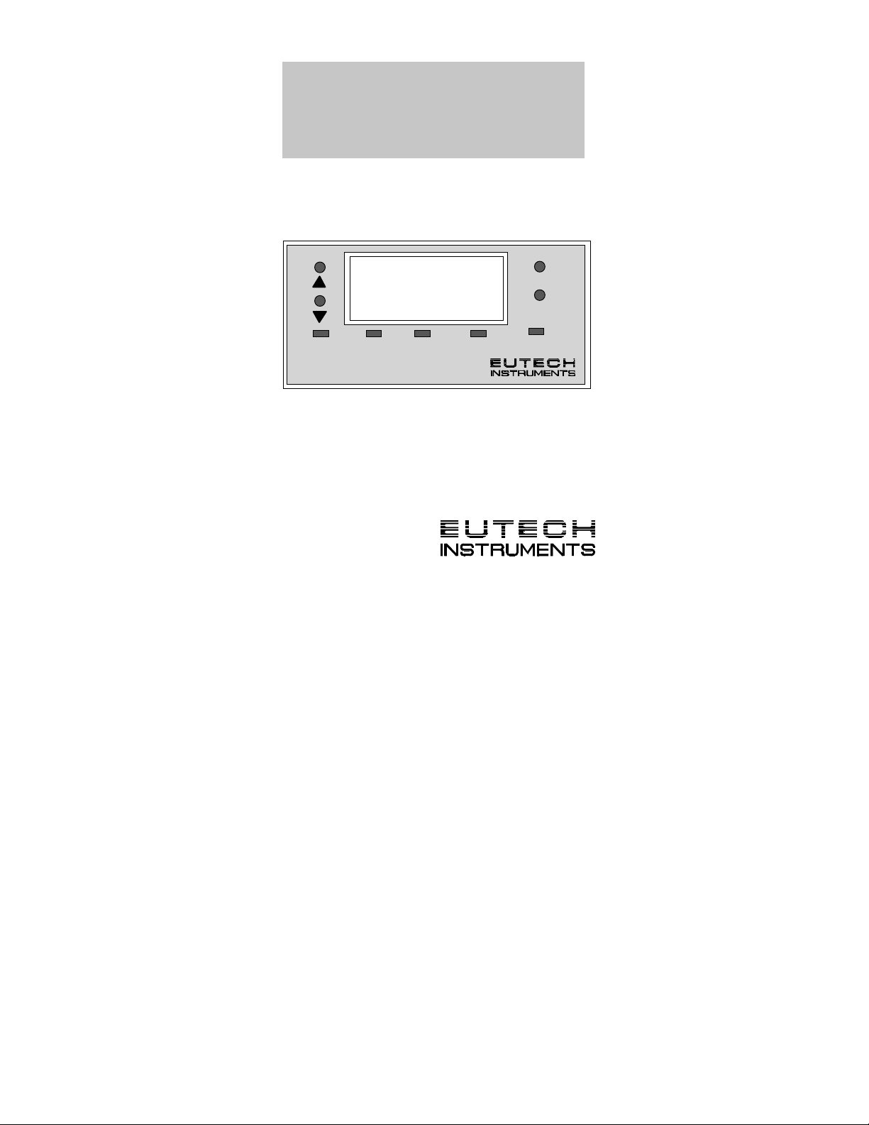
Alpha pH 100 C/CX
pH/ORP
Controller / Transmitter
INSTRUCTION MANUAL
MODE
H/OR
7.0
o
SETU
C
Technology Made Easy ...
READY
ENTER
RELAY
Page 2

Preface
This manual serves to explain the use of the Alpha pH
100 pH/ORP Controller/Transmitter. The units covered
are Alpha C and CX pH/ORP Controller/ Transmitter.
The instruction manual functions in two ways: first, as a
step by step guide to help you operate and understand
the operation of the unit and second, as a handy
reference guide.
The information presented in this manual is subject to
change as improvements are made, and does not
represent a commitment of Eutech Instruments Pte Ltd.
This instruction manual is written to cover as many
anticipated applications of the Alpha pH 100 C/CX
pH/ORP Controller/Transmitter as possible. If there are
doubts in the use, please do not hesitate to contact the
nearest Eutech Instruments’ Authorized Distributor or us
at (65) 778-6876.
Eutech Instruments cannot accept any responsibility for
damage or malfunction of the unit due to improper use
of instrument.
Copyright 1994 Eutech Instruments Pte Ltd.
Version 1.0
1
Page 3

TABLE OF CONTENTS
1. Introduction------------------------------------------------------------ 3
2. Getting Acquainted--------------------------------------------------4
2.1 Front Panel.............................................................4
2.2 Back Panel............................................................. 5
2.3 Selecting pH/ORP Measurement Mode..................6
2.4 Wiring.....................................................................6
3. Operating the Controller -------------------------------------------7
3.1 The Main Display.................................................... 7
4. Setting Up the Controller ------------------------------------------ 8
4.1 Setting and Changing the Password....................... 8
4.1.1 Setting New Password.........................................................8
4.1.2 Changing the Password.......................................................9
5. Calibrating the Controller---------------------------------------- 10
5.1 The Lower Level Menus........................................10
5.2 Calibrating for pH Measurement........................... 10
5.2.1 The CAL PH menu.............................................................10
5.3 Changing the Offset..............................................11
5.4 Calibrating for ORP Measurement........................12
5.5 Calibrating for Temperature Measurement ...........12
5.5.1 The CAL °C Menu..............................................................12
5.5.2 ATC ON/OFF.....................................................................13
5.6 Setting the Alarm Feature ...................................15
5.6.1 The Hi SET Menu ..............................................................15
5.6.2 The Hi HYS Menu..............................................................16
5.6.3 The Lo SEt Menu...............................................................17
5.6.4 The Lo HYS Menu .............................................................18
6. Using the Controller Current Loop for Datal oggi ng (for
Transmitter Model Only)------------------------------------------------- 19
7. Additional Information-------------------------------------------- 20
8. Appendix 1 - Jumper Positions (I nside Controller) ------- 21
9. Appendix 2A - Jumper Positions (pH) ----------------------- 23
10. Appendix 2B - Jumper Positions, ORP --------------------- 24
11. Appendix 3 - pH Offset / Slope-------------------------------- 25
12. Technical Specifi cations ---------------------------------------- 26
2
Page 4

1. Introduction
The alpha pH 100 series pH/ORP Controller/ Transmitter is the
latest innovation of process controllers from Eutech
Instruments. Incorporated with the ASIC (Applic ation Specific
Integrated Circuit) m i croprocessor technology, thi s panelmounted on-line controller provi des many user-friendly features
desirable in pH/ORP controll ers.
This versatile pH/ORP unit can be used either for measuring
and monitoring pH or ORP values at one time. It cannot be
used for measuring both parameters simultaneous l y. When
shipped, it will be set internally to the pH mode by means of an
internal jumper. This jumper can be reset by you to select
between the pH and ORP mode.
Some of the features of this Controller are :
• Automatic temperature compensation (with PT 100)
• Manual temperature compensati on setting without the
temperature probe
• Push button calibration up to 3 points
• Offset adjustment
• High and low alarm triggering relays
• User-defined password feature to prevent unauthorized
entry to change the calibration data, hysteresis function,
high and low setpoints information
• Alarm and operational message annunciators
• Hysteresis function t o prevent chattering of relays around
the setpoint
• High-end transmitter model with 4-20 mA current output
for datalogging purposes (pH CTP0100 only)
• Built-in memory backup to ensure that calibration and
other information will not be erased if power supply fails
• Switchable mains voltages of 110 VAC or 220 VAC via
user selectable internal j umper
3
Page 5

2. Getting Acquainted
SETU
Y
Y
2.1 Front Panel
The front panel consists of a 3 digit LED display together with 5
LED annunciators. There are also 4 k eys as shown below.
MODE
8 8 8
pH/ OR
The keys available are the ▲ (UP/INCREMENT), ▼
(DOWN/DECREMENT), MODE and ENTER keys.
The annunciators are pH/ORP, °C, SETUP, READY, and
RELAY. The function of the annunciator is to provide additional
information, for exampl e, the pH/ORP annunciator lights up i n
pH/ORP measurement mode. The READY annunciator lights
up when the pH/ORP stabilizes. RELAY lights up when any of
the HI SET or LO SET relays i s activated.
The MODE key allows you to select between pH or ORP
display, the temperature display or the SETUP menu di splay.
While in one of the SETUP menus, it als o functions as an
ESCAPE key. For example, while setting the Hi SET point, you
can press MODE key if you change your mind about changing
this information.
You can confirm changes or to enter into further levels of the
lower menu by pressing the ENTER key. The ▲
(UP/INCREMENT) and ▼ (DOWN/DECREMENT) keys allow
you to change information or t o select between different menus .
Holding down the key increases the scrolling speed, i.e.
changeover of 1st digit (ones) t o 2nd (tens) and then 3rd digit
(hundreds).
o
REA D
P
RELA
4
Page 6

2.2 Back Panel
The back panel consists of t wo connectors . The f irs t one is a 4way screw terminal and the second is a 12-way screw term inal.
Refer to the label on top of the unit for diagram.
The connection for the 4-way screw termi nals are (from the left
to right):
1. PT 100 connection
2. PT 100 connection
3. No connection
4. No connection
The connections for the 12-way screw term inals are (from left
to right),
5. Low Set Relay deactivated posit i o n
6. Low Set Relay center pole
7. Low Set Relay activated position
8. High Set Relay deactivat ed position
9. High Set Relay center pole
10. High Set Relay activat ed position
11. 4-20 mA - ve connection (for transmitter m odel s only)
12. 4-20 mA + ve connection (for transmitter m odel s only)
13. Protective earth
14. Protective earth
15. Neutral
16. Live
5
Page 7

2.3 Selecting pH/ORP Measurement Mode
You can set the appropriate pH/ORP measurement mode from
the jumper. See Appendix 1 for details on the jumper positions
for pH mode and Appendix 2 for jumper positions for ORP
mode.
2.4 Wiring
Connect the power supply to the GND (EARTH) - 13 or 14,
NEUTRAL - 15 and LIVE - 16 screw terminals. Make sure that
the power supply jumper setting matches the mains voltage
(110 VAC or 220 VAC). See Appendix 2 for the jumper setting
for the voltage selecti on.
Connect the pH electrode to the B NC connector at the back
panel. Wire up the P T 100 t emperature probe to the PT 100
connections (see back panel connections).
Power on the controller and the display automatically shows the
pH/ORP reading. The pH/ORP annunciat or l i ghts up. Once the
reading is stable, the READY annunciator lights up. However, if
the PT 100 temperature probe is not connected, automati c
temperature compens ation does not function. You c an set the
temperature at a select ed val ue. The temperature is set t o
factory default at 25.0
NOTE : Eutech Instrum ent s will not be responsible for
incorrect application of the controller using improper
voltage sources or wrong jumper set t ings.
o
C.
6
Page 8

3. Operating the Controller
R
o
R
R
3.1 The Main Display
Press MODE key to switch to three
main displays - the pH/ORP
display, the temperat ure display
7.4
pH/ORP
MODE
ENTE
and “SEt” display.
Press MODE key once to get into
the temperature meas urement.
The °C annunciator lights up when
you are measuring temperature.
24.0
C
MODE
ENTE
The display shows current
measured temperature (with A T C)
or the temperature that was set i n
MTC mode. Press MODE key
again and the display toggles to
SEt
MODE
ENTE
SETUP
the “SEt” for SETUP menu.
Press ENTER key to go into the lower-level setup menus while
the display shows "SEt". These lower-level menus allow
calibration of pH/ORP, Temperature and other parameters
including set password, Hi or Lo S et poi nts, and Hi or Lo
Hysteresis values.
7
Page 9
4. Setting Up the Controller
R
R
R
R
R
4.1 Setting and Changing the Password
4.1.1 Setting New Password
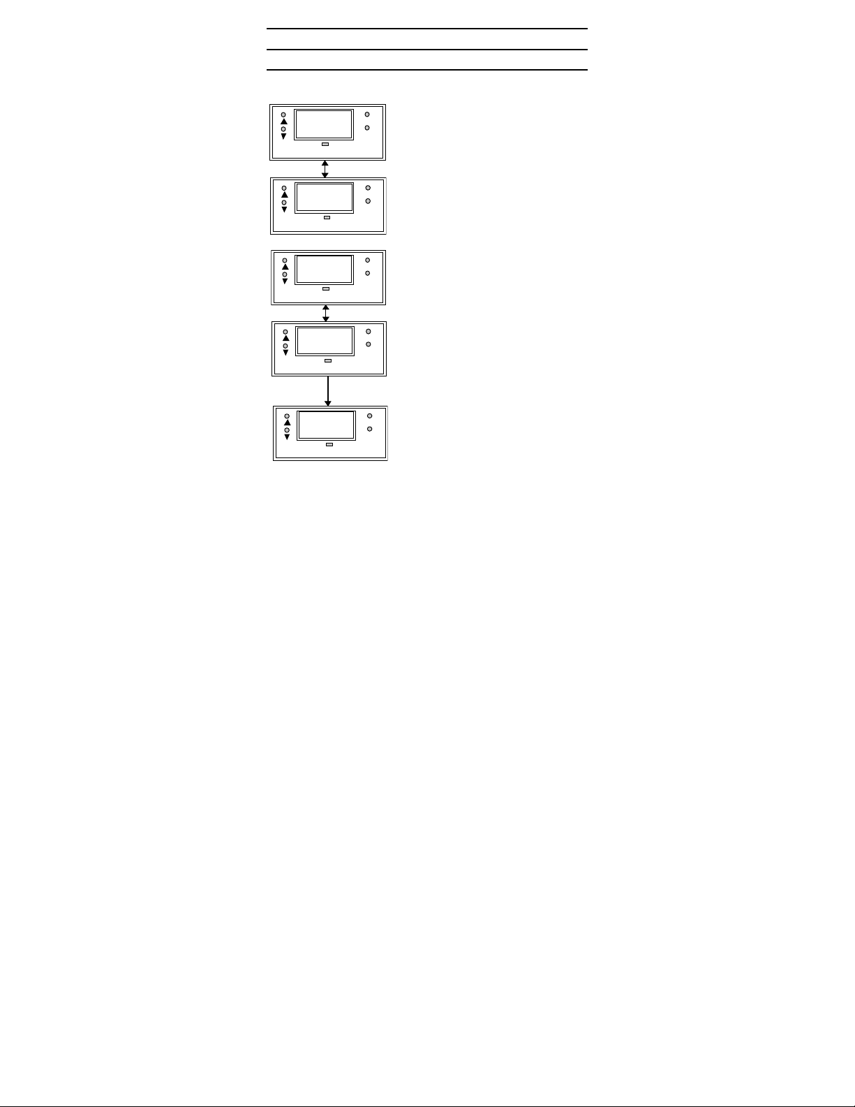
To set a password, press MODE key
MODE
CAL
SETUP
PH
SETUP
SEt
SETUP
id
SETUP
123
SETUP
menu, press ENTER and set your desired password by
following the above steps.
until the “SEt” is displayed.
ENTE
1. Press ENTER key and the
display shows "CAL” and “PH”
alternately. Press ▲ key once
and the display shows “SEt”
MODE
ENTE
“id”.
2. Press ENTER to enter your
desired password. Follow the
steps below (e.g. using a
password “123”).
MODE
1. Initially, the display shows "000"
ENTE
with the first digit blinking.
2. Use ▲ (UP/INCREMENT) key
to enter “1” on the 1st digit of
the password. Press ENTER
MODE
ENTE
once and the second digit will
blink. Similarly, enter the
second digit of the pass word “2”
and press ENTER key again.
Repeat with the third digit
accordingly.
3. Press ENTER key and the
MODE
ENTE
display shows “CAL” and ”PH”
alternately. Use ▲ or ▼ key to
get into the “SEt” and “id”
1. Once completed, press ENTER
to confirm and then press
MODE key to return to the pH
display.
8
Page 10

To calibrate the controller at any time, you may have to enter
the password that you set, in order t o access the calibration
mode. Once you have entered the pass word correctly, the
display shows "CAL PH” indicating that you are i n one of the
lower-level SETUP menus.
If you enter the wrong password, the display revert s back to the
pH display. Alternatively, if you prefer no password protection,
set the password to “000”, "CAL PH" immediately displays aft e r
you press ENTER key while you are in the "SEt" menu.
NOTE : The user set password is a protec tion code. Thus, it is
very important to keep thi s password strictly confi dential to
authorized personnel. You are advised to remember the
password that you have set, in order to prot ect the controller
settings and prevent any unauthorized tampering to the
system!
IMPORTANT : In case the password set is forgotten, use
the master password “555”.
4.1.2 Changing the Password
Enter the Set id menu with already set password or “555”.
Change a new password as per steps mentioned for setting the
password.
9
Page 11
5. Calibrating the Controller
5.1 The Lower Level Menus
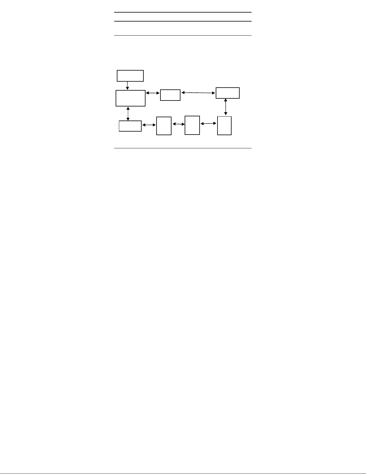
The "CAL PH/CAL OrP" display is the first menu seen upon
entering the lower-level menus, depending on which mode is
set. Press ▲ or ▼ key to display the various menus as shown
in the figure below. Press ENTER key to go to the lower level
menus.
START
CAL pH /
SEt id
Lo Hys
CAL OrP
CAL oC
Hi
SEt
Hi
Hys
Lo
SEt
5.2 Calibrating for pH Measurement
5.2.1 The CAL PH menu
1. Enter this menu by pressing t he MODE key twice to the
“SEt” display if you are in measurement mode.
2. Press ENTER key. If the password has been s et earlier,
key in the password using the m ethod des cribed in s ect ion
4.1. Press ENTER once to confirm. After you set the
correct password, you can see the “CAL” and “PH”
displays, blink al ternately.
3. Press ENTER key to enter i nto the pH calibration mode.
Dip both the pH electrode and temperature probe in the
standard solution for a few mi nutes.
4. When “CAL PH” displays, press ENTER key. The current
measured value (7 ±0.3 pH) will be displayed. Once the
reading stablizes, press ENTER to confirm.
5. Use ▼ keys to scroll to the other buf fer values “PH4” and
“PH10”, in that sequence. Press ENTER to confirm and
10
Page 12
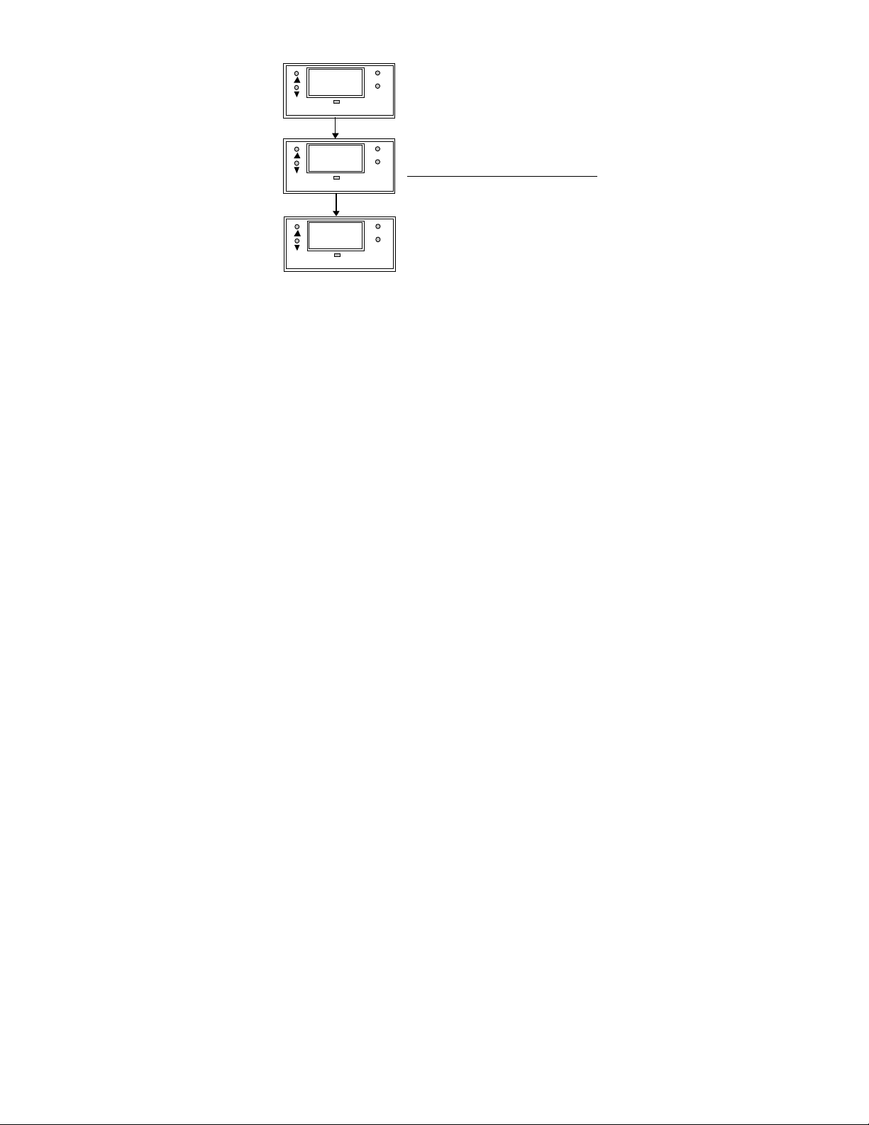
complete the pH cali brat i on, as fo pH 7.0. Press MODE
R
R
R
key to return to measurement mode.
Note : If the pH value is not near
CAL
SETUP
MODE
ENTE
to any buffer, pressing ENTER will
not calibrate the controll er. If at
any point, you decide not to
calibrate, you can return to the
previous mode by pressing the
MODE key.
Changing the Offset
5.3
If the controller cali bration has
PH
SETUP
MODE
ENTE
drifted, you can reset the of fset of
controller. First, go to the
7.0
SETUP
MODE
ENTE
calibration mode. Press ENTER
when pH7 is being displayed and
the present pH value is shown
(blinking). Using the ▲ or ▼ key,
change the current pH to 7.0. Press ENTER to confirm, and it
resets the pH calibrati on curve completely.
NOTE : Gently stir the electrode in a container f illed with buffer
solution to create a hom ogenous sample. Remem ber to rinse
the electrode before calibrati ng t o the next solution. Minimum
two points calibration is rec ommended. For full range accuracy,
three points calibration i s advised.
This is useful for on-line operations. For example, the
controller while in use shows a reading of pH 8.4. Using a
pre-calibrated portable meter, a measurement is made and
the reading shows pH 8.6. The offset of controller can be set
to 8.6 by going into the CAL m ode. While the controll er
displays “PH7”, press ENTER. The current reading will be
displayed. Using the ▲ or ▼ key, change the reading to pH
8.6 to reset the offset. Press ENTER to confirm offset setting.
Press MODE key returns to the controller back to the
measurement m ode. This allows a one-point calibration to be
made while the controller is still in operation to adjust f or
slight drifts of t he controller. For details, prefer to Appendix 3.
11
Page 13
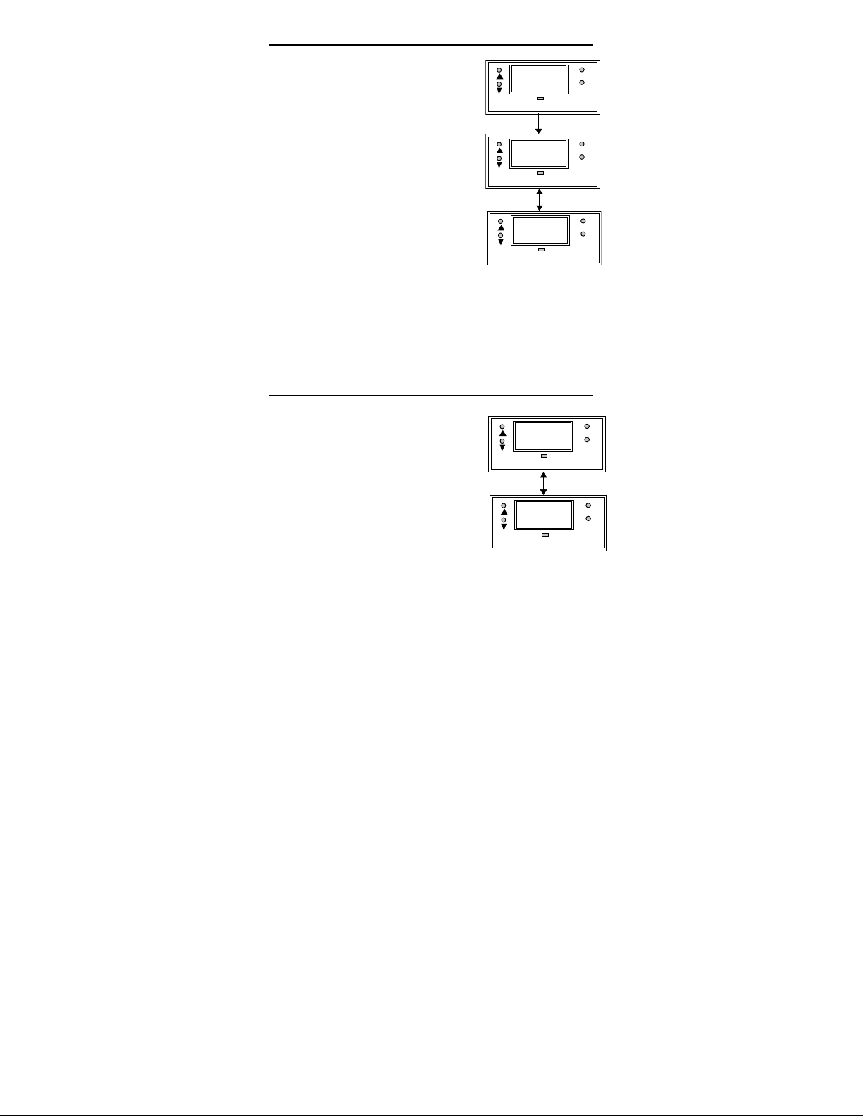
5.4 Calibrating for ORP Measurement
R
R
R
R
R
1. Make sure that the ORP mode is
set before calibration.
2. Enter this menu by pressing
MODE key twice to the “SEt”
SEt
SETUP
display if you are in meas urement
mode.
3. Press ENTER key. If the password
has been set earlier, key in t he
password using the method
described in section 4.1. Press
CAL
SETUP
ENTER once to confirm. After you
set the correct password, you can
see the “CAL” and “OrP” displays
blink alternately.
4. Press ENTER key to enter into the
ORP calibration mode. Di p both
OrP
SETUP
the ORP electrode and temperat ure probe i n the standard
solution for a few minutes .
5. When “CAL OrP” displays, you can see the present mV
value blinking, press ▲ or ▼ key to adjus t the mV value.
To confirm press ENTER key.
6. Press MODE key to return the controller to its
measurement m ode.
5.5 Calibrating for Temperature Measurement
5.5.1 The CAL °°°°C Menu
1. Enter this menu by pressing MODE
key twice to the “SEt” display if you
are in measurement mode.
1. Press ENTER key. If the password
has been set earlier, key in t he
password using the method
described in section 4.1. Press
ENTER once to confirm. After you
set the correct password, you see
CAL
SETUP
o
C
SETUP
MODE
ENTE
MODE
ENTE
MODE
ENTE
MODE
ENTE
MODE
ENTE
12
Page 14
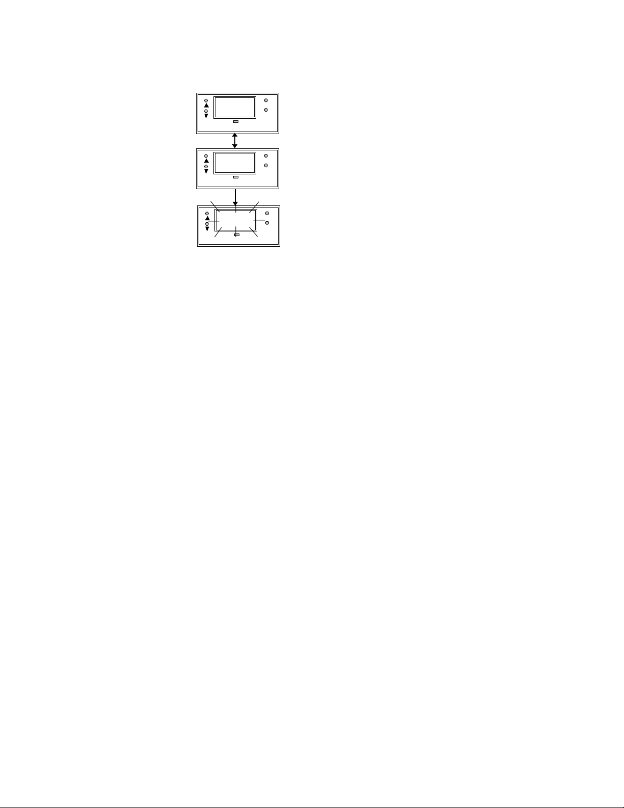
the “CAL” and “PH” display blinks alternatively. P ress ▼
R
A
R
R
key once, the display s hows “CAL”“
o
C” blinking.
2. Press ENTER and the display alternatively shows “Atc”
and “On” or “Atc” and “OFF”. Use ▲ and ▼ keys to
choose between both ATC ON and ATC OFF.
5.5.2 ATC ON/OFF
tc
SETUP
On
SETUP
23.5
SETUP
MODE
ENTE
MODE
ENTE
MODE
ENTE
ATC ON : If a PT 100 is connected,
use ▲ and ▼ keys to adjust the
temperature offset of the PT 100 by
± 5 °C. Dip the temperature probe
into the sample liqui d. Mak e sure
that the display is s et to ATC ON,
press ENTER and the display now
shows the actual temperat ure
reading (blinking).
Use ▲ and ▼ keys to adjus t the
reading to its actual temperature as measured by an external
thermometer. Onc e done, press
ENTER key and the display will
flash “CAL” “PH” alternatively.
13
Page 15

R
A
tc
R
R
SETUP
OFF
SETUP
MODE
ENTE
MODE
ENTE
ATC OF F : If a PT 100 i s not used,
then the ATC should be set to
OFF. In step 3 above, choose by
pressing ▲ and ▼ keys to select
ATC OFF. Then press ENTER.
The display will now show the
default of 25
o
C or the last set
value (blinking). Use ▲ and ▼ keys
to set your desired value. Pres s
ENTER to confirm and the display
shows “CAL” “Con”.
mode.
25.0
SETUP
MODE
ENTE
Note : For ATC OFF, you can
adjust the set temperature values
from 0.0 to 99.9
o
C. This value will
be used for its temperature
compensation e.g. pH i n the MTC
14
Page 16
5.6 Setting the Alarm Feature
R
R
R
T
This menu allows you to change the High and Low Set poi nt and
Hysteresis values. See Section 8 for hysteresis applications.
IMPORTANT : When SETUP mode is entered, the 4-20 mA
output (only for transmi tt er CX model) freezes and t he relay deactivates (if it was in an al arm condition).
5.6.1 The Hi SET Menu
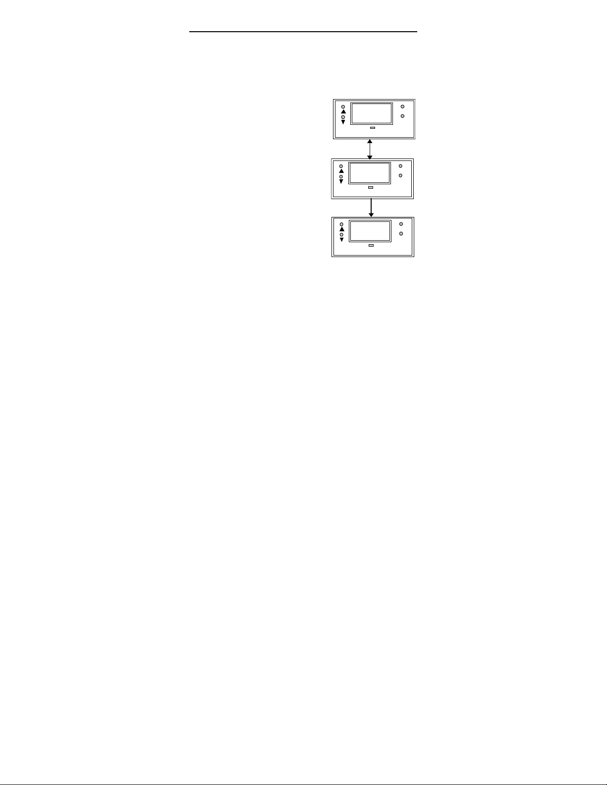
1. Enter this menu by pressing
MODE key twice to the “SEt”
display if you are in
measurement m ode.
2. Press ENTER key. If the
password has been set earlier,
key in the password using the
method described in sec tion
4.1. Press ENTER once to
confirm.
3. After you set the correc t
password, you see the “CAL”
and “PH” display blinks
alternately. Press ▼ key twice,
the display shows “Hi” “SEt”
blinking alternately.
1. Press ENTER key to access the
Hi SET menu and the displ ay
shows the last Hi SET value.
Use ▲ and ▼ keys to change
the value of the Hi SET point.
2. Press ENTER to confirm the
value of the Hi SET point.
3. Press MODE key to exit to the
measurement m ode. You can
E : The Hi SEt relay
activates if the c urrent
pH/ORP reading
exceeds Hi SET point
+ ½ Hi HYS value.
The Hi SET value
cannot be lower than
the Low SET value.
press MODE key (as an
ESCAPE key) to revert to the
measurement value if ENTER is
not pressed; the set value i s not stored into memory.
SEt
SETUP
Hi
SETUP
8.5
SETUP
MODE
ENTE
MODE
ENTE
MODE
ENTE
15
Page 17
5.6.2 The Hi HYS Menu
R
R
R
HYS
SETUP
Hi
SETUP
0.2
SETUP
MODE
ENTE
MODE
ENTE
MODE
ENTE
NOTE : The
maximum value of
Hysteresis is 0.2 pH
to 2.0 pH or 20 mV to
200 mV. The HI HYS
hysteresis is spread
equally on either side
of the Hi SET point.
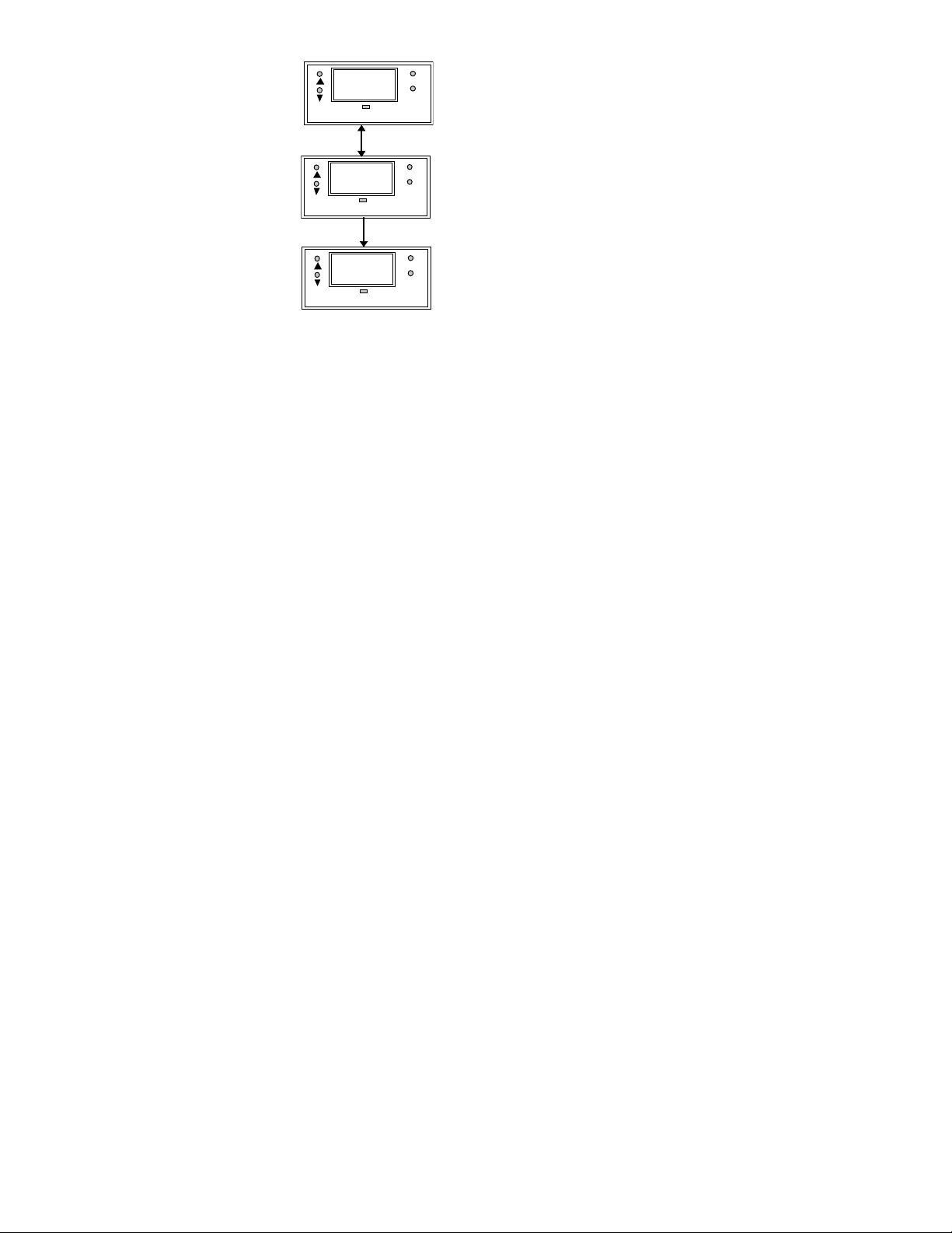
1. Enter this menu by pressing the
MODE key to the “SEt” display
if you are in the measurem ent
mode.
2. Press ENTER key. If the
password has been set earlier,
key in the password using the
method described in sec tion
4.1. Press ENTER once to
confirm. After you set the
correct password, you see the
“CAL” and “PH” display blinks
alternatively. Press ▼ key
thrice, the display shows “Hi”
“HYS” blinking.
1. Press ENTER key to access
the Hi HYS menu and the
display shows the last Hi HY S
value. Use ▲ and ▼ keys to
change the value of the Hi HYS
point.
2. Press ENTER to confirm the
value of the Hi HYS.
3. Press MODE key to exit to
measurement m ode. You can
press MODE key (as an
ESCAPE key) to revert to the
measurement value if ENTER is
not pressed; the set value i s not
stored into mem ory.
16
Page 18

5.6.3 The Lo SEt Menu
R
R
R
1. Ent er this menu by pressi ng
MODE key twice to the “SEt”
display if you are in
measurement mode.
2. Press ENTER key. If the
password has been set
earlier, key i n the password
using the method described in
section 4.1. Pr ess ENTER
once to confirm.
3. Af ter you set the corr ect
password, you see the “CAL”
and “PH” display blinks
alternately. Press ▼ key four
times, the display shows “Lo”
“SEt” blinking alternately.
1. Press ENTER key to access
the Lo SET menu and the
display shows the l ast Lo SET
value. Use ▲ and ▼ keys to
change the value of the Lo
SET point.
2. Press ENTER to confirm the
value of the Lo SET point.
3. Press MODE key to exit to
measurement mode. You can
press MODE key (as an
ESCAPE key) to revert to the
measurement value if ENTER
is not pressed; the set value is
not stored into memory.
SEt
SETUP
Lo
SETUP
5.0
SETUP
MODE
ENTE
MODE
ENTE
MODE
ENTE
NOTE : The Lo SEt
relay activates if the
current pH/ORP
reading exceeds Lo
SET point - ½ Lo
HYS value. The Lo
SET value cannot be
higher than the Hi
SET value.
17
Page 19
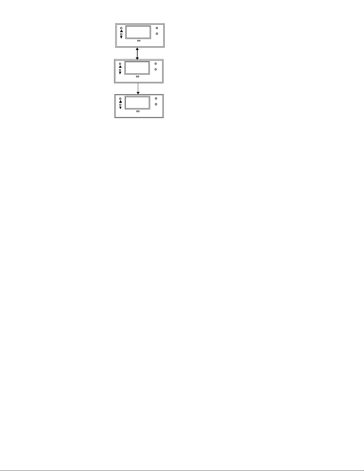
5.6.4 The Lo HYS Menu
R
R
R
HYS
SETUP
Lo
SETUP
0.2
SETUP
MODE
ENTE
MODE
ENTE
MODE
ENTE
NOTE : The maximum
value of Hysteresis is
0.2 pH to 2.0 pH or 20
mV to 200 mV. The Lo
HYS hysteresis is
spread equally on
either side of the Lo
SET point.
1. Ent er this menu by pressi ng
the MODE key to the “SEt”
display if you are in the
measurement mode.
2. Press ENTER key. If the
password has been set earlier,
key in the password using the
method described in s ection
4.1.
3. Press ENTER once to confirm.
After you set the correct
password, you see the “CAL”
and “PH” display blinks
alternatively. Press ▼ key five
times, the display shows “Lo”
“HYS” blinking alternately.
1. Press ENTER key to access
the Lo HYS menu and the
display shows the l ast Lo HYS
value. Use ▲ and ▼ keys to
change the value of the Lo
HYS point.
2. Press ENTER to confirm the
value of the Lo HYS. Press
MODE key to exit to the
measurement mode. You can
press MODE key (as an
ESCAPE key) to revert to the
measurement value if ENTER
is not pressed; the set value is
not stored into memory.
IMPORTANT : The Lo SET + ½ Lo HYS should be less
than Hi SET - ½ Hi HYS i.e. Hi SET and Lo SET value (in
consideration of the hysteresis band) can never overlap. Lo
HYS and Hi HYS can be set independent of each other; this
allows non-symmetrical hysteresis option.
18
Page 20

6. Using the Controller Current Loop for
Datalogging (for Transmitter Model Only)
The 4-20 mA Current Loop
A 4-20 mA current loop can be connected if a remote data
logging is required. The current will be proportional to the
pH/ORP displayed on the panel displ ay. The 4-20 m A current
loop can drive a load resistance of no more than 200Ω.
If the pH is less than 0.0 pH, the current s ignal will be set to
approximately 0 mA. If the pH is great er than 14.0 pH, it will be
set to approximately 21 mA . I n thi s way, the remote data logger
can detect when out of range conditions aris e. Pleas e note that
the 4-20 mA loop is not galvani cally isolated from the s ource.
19
Page 21
7. Additional Information
A
A
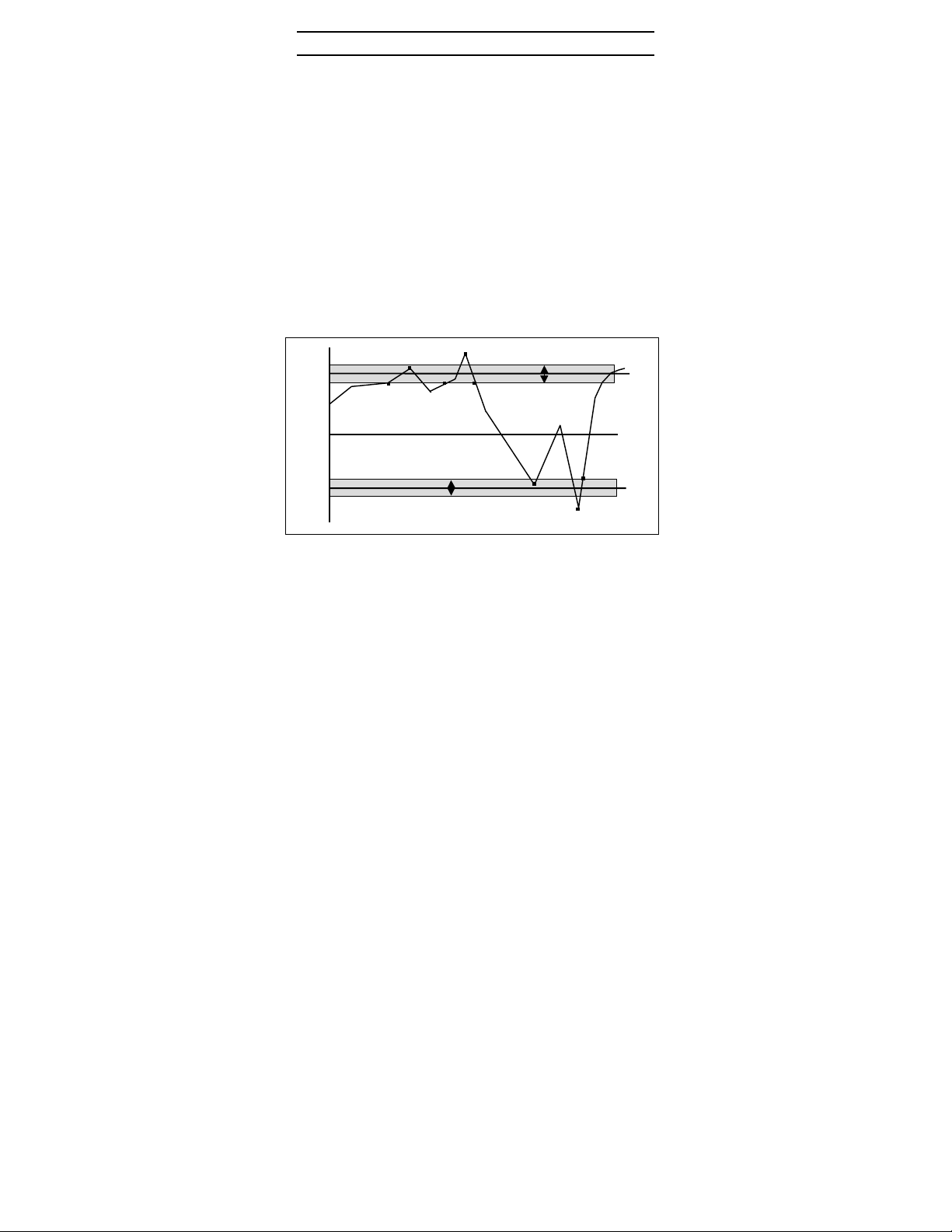
The controller allows you to set High and Low alarm s that
switch on or off relays, and ac tivating or deactivating devices
linked to the controller. In cases where the pH/ORP values
fluctuate close t o the high or low setpoints, the relays will
continuously switch on/off very quickly and may cause
problems to the linked devi ces. The hysteresis band all ows you
to set an allowable range of fluctuations to prevent the relays
from activating and deac tivating too quickly. S ee bel ow.
It is not possible to set the high set point lower than the l ow set
point and vice versa (taking t he hysteresis band into
consideration). For example, when the high set point is 8.50
pH and the high hysteresis band is set at 0.40 pH, then the low
setpoint cannot be set at higher than 8.50 - ½ Hi HYS.
NOTE : The shaded area indicates the hys teresis band.
D
Hi
Hys
B
C
Hysteresis Band
E
ctual
pH
Hi
Set
Lo
Hys
Hysteresis Band
F
H
Lo
Set
G
20
Page 22

Explanation of the diagram in the previous page
F
A - Reading reaches (Hi SET - ½ HI HYS), the Hi-Set relay
remains inactivat ed.
B - Reading reaches above High Setpoint but below (Hi SET +
½ Hi HYS), Hi-Set relay remains inactivated.
C - Reading reaches between (Hi SET - ½ Hi HY S), the Hi-Set
relay remains inacti vated.
D - Reading reaches above (Hi SET + ½ Hi HYS), and t he Hi-
Set relay is activated.
E - The Hi-Set relay is inac tivated only when the reading falls
below (Hi SET - ½ Hi HYS).
F - Reading reaches between (Lo SET - ½ Lo HYS), the Lo-
Set relay remains inactivated.
G - Reading reaches below (Lo SET - ½ Lo HYS), the Lo-Set
relay is activated.
H - The Lo-Set relay remains activated until the reading goes
above the (Lo SET + ½ Lo HYS)
Appendix 1 - Jumper Positions (Inside Controller)
21
Page 23

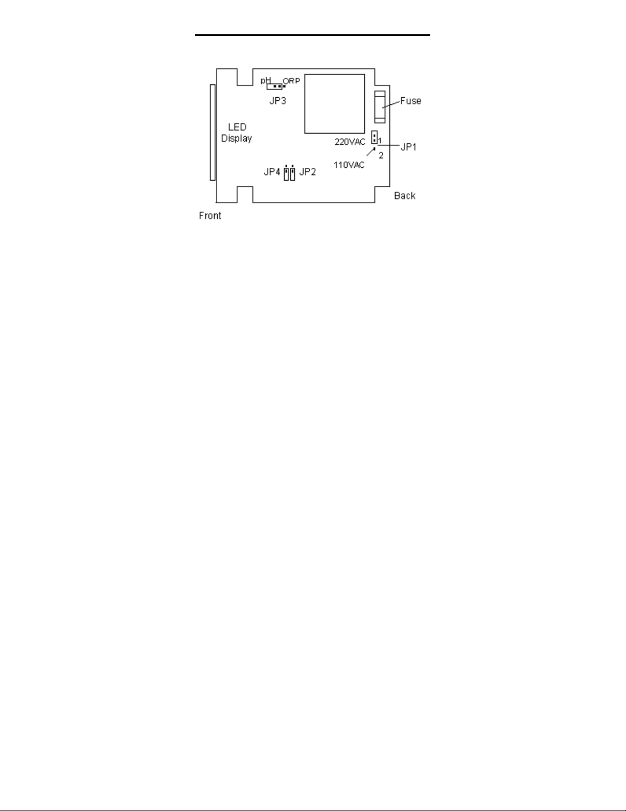
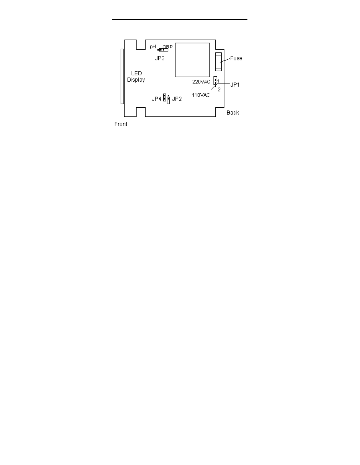
JP1 Selects the input voltage between 110
VAC or 220 VAC
JP3 & JP4 Selects for pH or ORP mode. Please
refer to Appendix 2A and 2B for the
diagrams
JP2
OPEN
SHORT
(DEFAULT)
Terminals 5 & 6,
8 & 9
6 & 7,
9 & 10
5 & 6,
8 & 9
6 & 7,
9 & 10
Power On OPEN CLOSE CLOSE OPEN
pH within
OPEN CLOSE CLOSE OPEN
setting
pH
CLOSE OPEN OPEN CLOSE
exceeding
setting
Fuse Note that there is a fuse internal to the
controller. Before opening the unit,
ENSURE that the power cable is
physically separ ated from the mains
supply. Replace the fuse with the one
recommended by the manufacturer.
22
Page 24
Appendix 2A - Jumper Positions, pH
Jumper Positions - inside the Controller
23
Page 25
Appendix 2B - Jumper Positions, ORP
Jumper Positions - inside the Controller
24
Page 26

Appendix 3 - pH Offset / Slope
A
mV Axis
Current pH curve
pH Axis
25
4.5
djusted pH curve
7.0
7.5
10.0
10.5
Page 27

8. Technical Specifications
pH Range 0.0 to 14.0 pH
Resolution 0.1 pH
Relative Accuracy +/- 0.1 pH
mV Range -1250 to +1250 mV
Resolution 10 mV
Relative Accuracy +/- 10 mV
Temperature
Compensation
Temperature 0 to 100 oC
Resolution 0.1 oC
Relative Accuracy +/- 0.5 oC
Sensor PT 100
Calibration Push-bush 1 to 3 points
Calibration Options pH 4.0, 7.0 and 10.0
Output 4-20 mA, screw terminals (non-isolated);
Display LED, 3 digits
Inputs BNC, screw terminals
Input Impedance
Input Bias Current 50 pA max. at 25 oC
Recommended Input
Cable Length
Relays
No. Of Relays
Maximum Voltage
Maximum Current
High Hys. Band
Low Hys. Band
Power Requirements 110 VAC or 220 VAC (Jumper selectable)
Environmental
Requirements
Operating
Storage
Humidity Limits
Storage Temp. Range 0 to 50 oC
Dimensions 1/8 DIN size; 96 (L) x 48 (H) mm (Front panel)
Automatic / Manual (0 to 100.0 oC)
Max. load 200 Ω
10 ^ 12 Ω
Less than 5 meters
2 - High set & Low set SPDT
240 VAC
0.2 to 2.0 pH or 20 to 200 mV
0.2 to 2.0 pH or 20 to 200 mV
10 to 95% RH (non condensing)
3A
0 to 50 oC
-10 to 60 oC
26
Page 28

NOTES
27
 Loading...