

Page 1

200 Mbps HomePlug® AV
To Fast Ethernet Adapter
UPL5500-201(K) User Manual
Copyright EUSSO Technologies, Inc. All rights reserved.
Page 2

FCC Warning
This equipment has been tested and found to comply with the
regulations for a Class B digital device, pursuant to Part 15 of the
FCC Rules. These limits are designed to provide reasonable
protection against harmful interference when the equipment is
operated in a commercial environment. This equipment generates,
uses, and can radiate radio frequency energy and, if it’s not installed
and used in accordance with this user’s guide, may cause harmful
interference to radio communications. Operation of this equipment in
a residential area is likely to cause harmful interference, in which
case the user will be required to correct the interference at his own
expense.
CE Mark Warning
This is a Class B product. In a domestic environment, this product
may cause radio interference, in which case the user may be
required to take adequate measures.
Rev.A1-02
Page 3

Table of Contents
TABLE OF CONTENTS........................................................................I
INTRODUCTION.................................................................................. 1
ABOUT THE 200M HOMEPLUG® AV TO FAST ETHERNET ADAPTER ..... 1
TERMS/USAGE ..................................................................................... 1
PRODUCT FEATURES............................................................................. 1
IDENTIFYING EXTERNAL COMPONENTS................................... 2
LED INDICATORS ................................................................................. 2
QUICK SETUP BUTTON ......................................................................... 3
INSTALLATION.................................................................................... 3
CONNECTING TO NETWORK .................................................................. 4
CONFIGURATION UTILITY ............................................................. 5
INSTALL CONFIGURATION UTILITY....................................................... 5
USING THE HOMEPLUG AV UTILITY..................................................... 6
Device Information.........................................................................7
Network Information....................................................................... 7
QoS................................................................................................. 8
Network ID ................................................................................... 10
Upgrade.........................................................................................11
About............................................................................................. 12
SPECIFICATIONS..............................................................................13
Page 4

1
INTRODUCTION
Thanks for purchasing of the 200M HomePlug® AV to Fast Ethernet
Adapter. This Adapter will allow your Ethernet device to connect to
other Ethernet devices through AC power line.
About the 200M HomePlug® AV to Fast Ethernet Adapter
The 200M HomePlug® AV to Fast Ethernet Adapter allows user to
connect with other Ethernet enabled devices through AC power line
at home or office.
The 200M HomePlug® AV to Fast Ethernet Adapter is designed to
provide the Plug-and-Play installation, user just connected the
Ethernet cable on the Adapter and Ethernet enabled device and
pluged the Adapter to AC outlet.
Terms/Usage
In this guide, the term “the PLC” refers to the 200M HomePlug® AV
to Fast Ethernet Adapter.
Product Features
z Compliant with 200M HomePlug® AV specifications
z Compliant with IEEE 802.3 10BASE-T Ethernet, IEEE 802.3u
100BASE-TX specification
z ANSI/IEEE 802.3 Auto-negotiation and Auto MDI and MDIX
z Powerline speed up to 200Mbps
z 3 LED indicators for Power, HomePlug Activity and Ethernet port
Link/Activity
z Support quickly setup button
Page 5

IDENTIFYING EXTERNAL COMPONENTS
This section identifies all the major external components of the 200M
HomePlug® AV to Fast Ethernet Adapter.
10/100M Fast Ethernet Port
Connect to Ethernet enabled device.
AC Power Plug
Plugging into the AC power outlet.
LED Indicators
LED Display Status description
On
The PLC is connected to the AC power line and operation
normal.
Off The PLC is not connected to the AC power line.
Power
Blinking The PLC is goes to firmware upgrade or on pairing.
On The PLC is the PowerLine addresser.
Off The PCL is not join to PowerLine group
HomePlug
Blinking The PLC is the PowerLine joiner.
On The PLC is connected to the Ethernet network
Off The PLC is not connect to Ethernet network
Ethernet
Blinking
The PLC is on transmission or receives data to/from
Ethernet network.
2
Page 6

3
Quick Setup Button
The button is use to setup the PLC to join into the PowerLine network
group quickly.
Resetting the network ID
Press the Quick Setup button until all LEDs extinguish (more than
10 seconds), the PLC will reset the network ID sett ing and generate
a random network ID. Always reset the network ID before
pairing the PLC.
Pairing the PLC
When new PLC adapters want to join to existing PowerLine Network,
press the Quick Setup button on any exist PLC adapter and press
the new PLC adapter’s Quick Setup button within three seconds at
the same time, the Power LED will start blinking, it means the PLC
adapters goes to pairing process, when finished the pairing, the
Power LED will be steady on.
INSTALLATION
The 200M HomePlug® AV to Fast Ethernet Adapter is designed to be
simple and easy installation.
10/100M Fast Ethernet Port
Connect to Ethernet enabled device.
AC Power Plug
Plugging into the AC power outlet.
LED Indicators
Detailed LED description shows on Page 3.
Quick Setup Button
The button is use to setup the PLC to join into the HomePlug network
group quickly.
Page 7
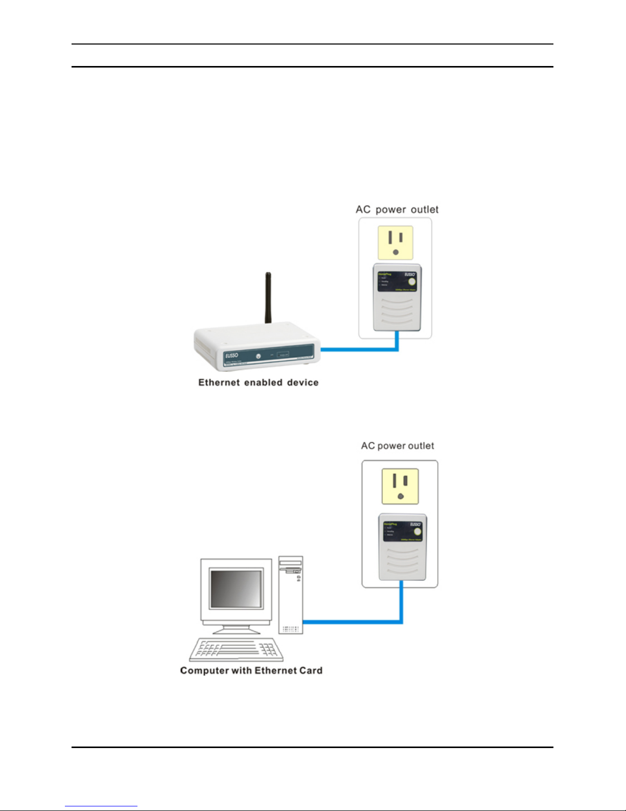
Connecting to network
You can connect the 200M HomePlug® AV to Fast Ethernet Adapter
directly to the PC’s network adapter, switch, or any other Ethernet
enabled device.
Note: The Ethernet port on the Adapter supports 10/100M Auto-MDI/MDIX
function, you can use a straight-through or a crossover Ethernet cable when
connecting to another Ethernet enabled device.)
or
4
Page 8

Configuration Utility
The HomePlug AV Utility for Windows OS enables the users to
identify PLC devices on the power line network, measures data rate
performance, ensures privacy and performs diagnostics by setting
user defined secure power line networks.
Install Configuration Utility
Insert the HomePlug AV utility CD into your CD-ROM drive and the
Auto-run program will appear. Alternatively this can also be done
manually by double clicking the au torun.exe file on the CD.
Click the “Enter” on the menu to open the HomePlug AV Utility, the
install wizard will begin the software installation. Follow the install
wizard instructions completed the HomePlu g AV Utility install.
5
Page 9

Using the HomePlug AV Utility
To start the HomePlu g AV Utility, double cl ick the icon on the
desktop, the Configuration Utility will be executed.
The Configuration Utility was divided into four functions, Device
Information, Network Informat ion, QoS, Security, Upgrade and About,
for details instruction, follow the below sect ion.
6
Page 10

Device Information
The Device Information screen shows the device information
including the MAC address, Firmware Version and the connected PLC
device.
Network Information
The Network Information screen shows all devices that were on the
power line network are listed here. Devices that are active on the
current logical network will show a transfer rate and receiver rate.
7
Page 11
QoS
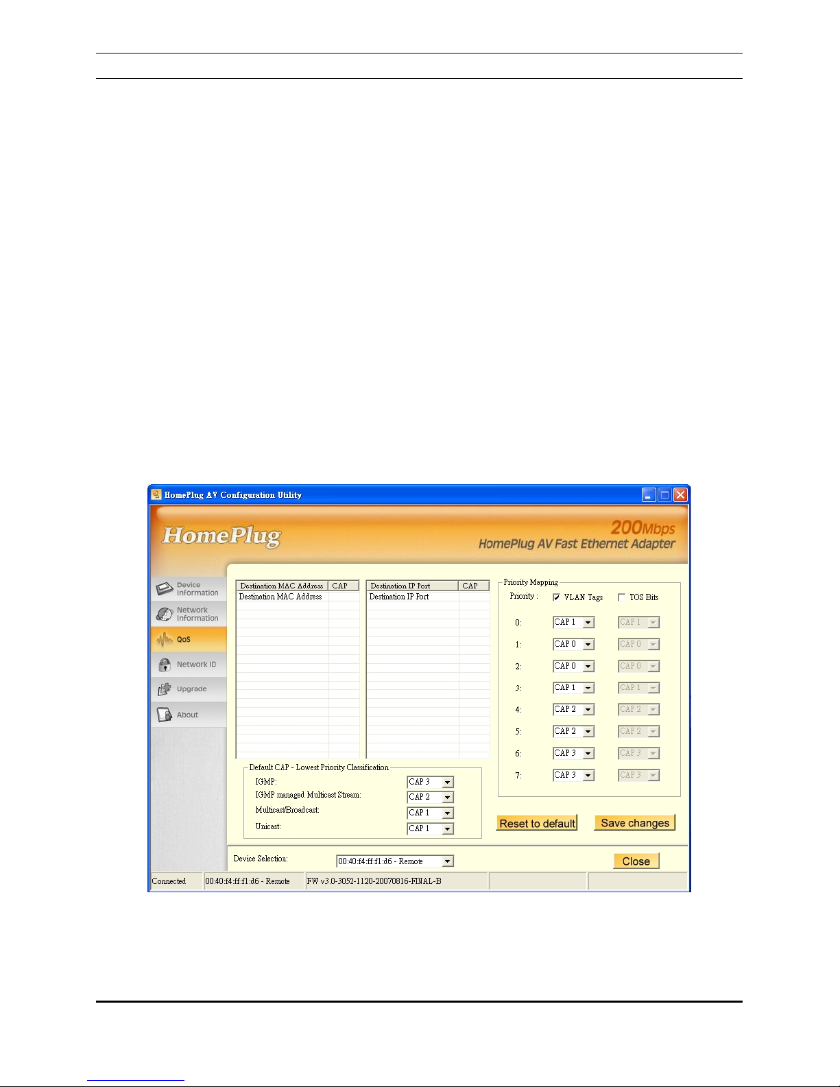
QoS requirements are different for various data types such as
streaming video or music, voice and raw data. To provide higher QoS
for streaming data, priority levels can be set using tags at the
beginning of data frames. Virtual Local Area Network (VLAN) 802.1p
priority tags on Ethernet frames are used to specify 8 (0 – 7) levels
of ‘user priority’.
The 200M HomePlug® AV to Fast Ethernet Adapter allows 4 levels of
Channel Access Priority (CAP (0 – 3)). Therefore, the 8 levels of
VLAN Ethernet tags must be mapped to the 4 levels of CAP priority,
where CAP 3 is the highest priority and CAP 0 is the lowest. CAP 3
priority might be used for voice and network management frames,
CAP 2 is used for streaming video and music while CAP 1 and CAP 0
are used for data. Mapping VLAN tags or TOS bits to CAP levels is
easily done using the VLAN Priority Mappin g function on the QoS tab
window.
8
Page 12

9
Device Selection
Select the device from the drop down list and configure the device
selected.
List View
The QoS tab includes two list views to provide simple channel access
priority (CAP) classification for individual MAC addresses and IP Ports.
There is a collective limit of eight across both lists. No delimiters,
colons, or dashes are allowed in the MAC address format.
Priority Mapping
The ‘Priority Mapping’ group contains both VLAN and TOS Bit
mapping capability. When selected, packets matching the VLAN or
TOS Bit priority will be assigned the Powerline contention priority
(Channel Access Priority, CAP) as set in the corresponding dropdown
box. If a packet has both VLAN and TOS in it, VLAN will override
TOS.
Default CAP
The ‘Default CAP’ group allows for default priority mapping of packets
that do not have a VLAN or TOS bit. Settings are available for Unicast
(directed to a host).
‧ IGMP - (default CAP 3) - sets the channel access priority for IGMP
frames - these are the group management frames, not the
stream data
‧ IGMP managed Multicast Stream (default CAP 2) - sets the
default channel access priority for stream data belonging to a
snooped IGMP multicast group.
‧ Multicast/Broadcast - sets the default CAP1 for multicast frames
not in a snooped group and for broadcast frames.
‧ Unicast - (default CAP 1) - sets the default channel access
priority for unicast frames not matching any other classification
or mapping.
Page 13

Reset to default
Press the Reset to default button to restore the factory default QoS
setting.
Save changes
Press the Save changes button to save and execute the modified
QoS setting.
Network ID
This Network ID window is used to set or change the network group
id.
Device Selection
Select the device form drop down list will be configure.
10
Page 14

Setting the local device Network ID
If the Device Selection is selected to local
device
, enter the network ID in Network ID filed
then click Save changes button to sets the entered Network ID.
If the Device Selection is selected to remote
device
, enter the network ID in Network ID filed
and enter the remote device access key in DAK password field then
click Save changes button to sets the entered Network ID. (The
DAK password is show on each PLC’s device label).
Reset to Default
Press the Reset to Default button to restore the factory default
network id setting for “HomePlugAV”.
Upgrade
Device Selection
Select the device form drop down list will be configure.
Reboot Device
Press the Reboot Device button to reset the node, which will restore the initial factory
configuration.
11
Page 15

Firmware Upgrade
To upgrade the firmware, press the Firmware Upgrade button and
then locate the two firmware files (PIB file *.pib and firmware file
*.nvm), the confirmation window s will pop up, click Yes to start the
firmware upgrade or click No to abort the firmware upgrade.
About
The About screen shows the HomePlug AV Configuration Utility
information including utility version and release date.
12
Page 16

13
SPECIFICATIONS
Standards:
200M HomePlug AV
IEEE 802.3 Ethernet
IEEE 802.3u Fast Ethernet
Data Speed:
Ethernet: 10/100Mbps (Link speed)
PowerLine: Up to 200Mbps
Frequency band:
2MHz ~ 30MHz
Modulation
Technology:
OFDM
Secutiry:
128-bit AES. Link Encryption with Key management
for secure powerline communications
Range Coverage:
Up 300 meters (depends on environment)
LED indicators:
Power, HomePlug, Ethernet
Ethernet port:
1 x 10/100Mbps Ethernet with Auto negotiation and
Auto-MDI/MDIX
EMI Compatibility:
FCC Class B, CE Class B
Safety:
UL, CB
Dimensions:
91.5 x 65 x 40 mm (without AC power plug)
Storage
Temperature:
Storage: -10
o
C ~ 70 oC
Operation: 0
o
C ~ 40 oC
Humidity:
(non-condensing)
Storage: 10% ~ 90%
Operation: 10% ~70%
Power
100 ~ 240VAC, 50 ~ 60Hz
Power
Consumption
4.2 watts. (max.)
Configuration
Utility:
Windows 2000
XP 32bit/64bit
Vista 32bit
 Loading...