

Page 1
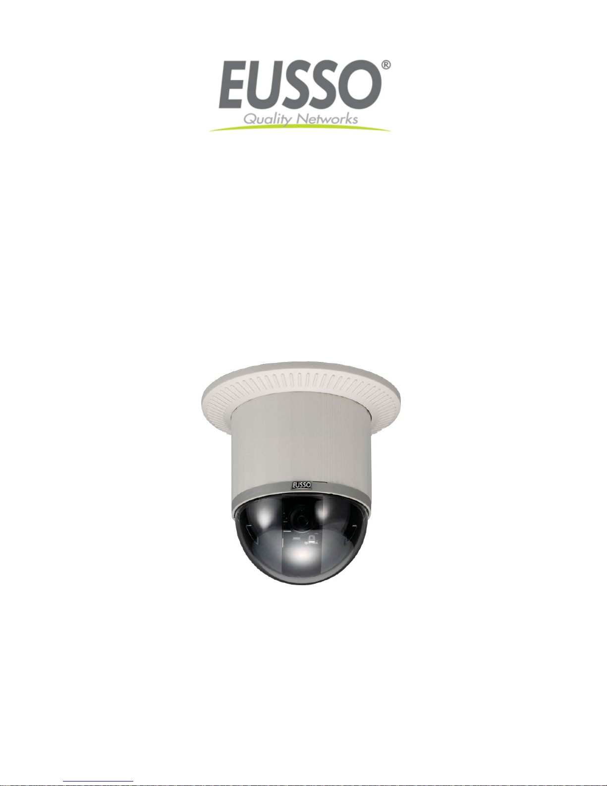
Indoor/Outdoor Dual-Codec
CCD IP Speed Dome Camera
UNC7825-Series User’s Manual
Version: 1.4
Date: 03/26/2008
Copyright EUSSO Technologies, Inc. All rights reserved
1
Page 2

Content
INTRODUCTION ................................................................................................................... ................................................ - 4 -
WHAT IS NETWORK DOME CAMERA?......................................................................................................... - 4 -
FEATURES...................................................................................................................................................................... - 5 -
1 PHYSICAL C ON NECTIONS...........................................................................................................................................- 7 -
1.1 STRUCTURAL ELEMENT................................................................................................................................................. - 7 -
1.2 CONNECTION JACK AND CABLE REQUIREMENT............................................................................................................. - 8 -
1.3 DIP SWITCH SETTING.................................................................................................................................................. - 10 -
1.4 NDC ID ADDRESS SETTING REFER CHART...................................................................................................................- 11 -
2 INSTALLATION..............................................................................................................................................................- 12 -
2.1 INSTALLATION PREVIEW.............................................................................................................................................. - 12 -
2.2 HARDWARE INSTALLATION.......................................................................................................................................... - 13 -
2.3 SOFTWARE INSTALLATION ........................................................................................................................................... - 25 -
2.4 NETWORK CONFIGURATION......................................................................................................................................... - 26 -
3 USAGE OF WEB-BASED USER INTERFACE...........................................................................................................- 30 -
3.1 BROWSE LIVE VIDEO................................................................................................................................................... - 30 -
3.2 VIDEO AND AUDIO RECORDING................................................................................................................................... - 33 -
3.3 VIDEO CONFERENCE.................................................................................................................................................... - 34 -
4 CONFIGURATION OF WEB-BASED USER INTERFACE......................................................................................- 37 -
4.1 CONFIGURATION PREVIEW........................................................................................................................................... - 37 -
4.2 CONFIGURATION OF A/V SETTING............................................................................................................................... - 38 -
4.3 SETTING EXTERNAL SOURCES..................................................................................................................................... - 42 -
4.4 PTZ SETTINGS............................................................................................................................................................. - 43 -
4.5 ON SCREEN DISPLAY................................................................................................................................................... - 48 -
4.6 CONFIGURATION OF NETWORK SETTING ..................................................................................................................... - 49 -
4.7 CONFIGURATION OF SYSTEM ....................................................................................................................................... - 53 -
4.8 CONFIGURATION OF EVENT ......................................................................................................................................... - 57 -
5 ADVANCED SETTINGS FOR UNC7825-O................................................................................................................. - 60 -
5.1 CALL OUT THE OSD SETUP MENU .............................................................................................................................. - 60 -
5.2 SET UP FUNCTIONS...................................................................................................................................................... - 61 -
6 ADVANCED SETTINGS FOR UNC7825-OW............................................................................................................. - 70 -
6.1 CALL OUT THE OSD SETUP MENU .............................................................................................................................. - 70 -
6.2 SPECIAL FUNCTIONS.................................................................................................................................................... - 71 -
6.3 CAMERA SETTINGS...................................................................................................................................................... - 74 -
6.4 LENS CONTROL ........................................................................................................................................................... - 86 -
7 ADVANCED SETTINGS FOR UNC7825-OT..............................................................................................................- 88 -
- 1 -
Page 3

7.1
CALL OUT THE OSD SETUP MENU .............................................................................................................................. - 88 -
7.2 SETUP FUNCTIONS....................................................................................................................................................... - 90 -
8 SURVEILLANCE SYSTEM CONFIGURATION..................................................................................................... - 101 -
8.1 NDC AND KEYBOARD ............................................................................................................................................... - 101 -
8.2 INITIAL POWER UP INSPECTION ................................................................................................................................. - 103 -
8.3 OPERATING NDC WITH KEYBOARD........................................................................................................................... - 103 -
9 SPECIFICATIONS........................................................................................................................................................- 113 -
APPENDIX A. UPGRADING THE SOFTWARE............................................................................................................- 118 -
APPENDIX B. UPGRADE CUSTOM WEB PAGES ......................................................................................................- 121 -
APPENDIX C. EMERGENCY FACTORY DEFAULT...................................................................................................- 123 -
APPENDIX D. QUICK REFERENCE TABLE FOR KEYBOARD CONTROL.........................................................- 124 -
APPENDIX E. TROUBLE SHOOTING...........................................................................................................................- 126 -
- 2 -
Page 4

WARNING and PRECAUTIONS
Please read the manual before attempting installation or operation.
Please be aware of the following:
1. Don't use any chemical detergent to clean the machine surface, use a damp cotton cloth only. Regularly clean the dome
cover to ensure more accurate focusing.
2. Please install the Network Dome Camera in a dry area; water and high humidity may cause damage on internal parts.
External housing should be used for outdoor installations.
3. Please use parts supplied by the manufacturer only, any unqualified part using in the equipment may violate the warranty.
4. Avoid installing the equipment in an unstable surface. Ensure that the equipment is attached to something that is fixed
solidly in place. Falling equipment may injure personnel and damage the equipment.
5. Do not install the equipment near any flammable materials as they may cause a fire or personal injury.
6. Avoid running video cable and signal cable through or passing interference sources such as video waves, broadcast
stations, power generators, elevator motors or high voltage areas, etc. as they may cause interference.
7. Ensure the power cable is properly attached. Improperly attached cables may cause a serious short circuit or fire.
8. Correct cable connection is important. Do not place any object on the connection cable and change the cable if there is
damage on cable. Violation may cause short circuit, fire and injury.
9. Make sure ground is well connected to avoid damage caused by lightning.
10. Do not put any foreign objects inside the equipment and do not spray any liquid on equipment. This will avoid short circuit
damage.
11. Do not touch power connection with wet hands to avoid short circuit or electricity shock.
12. Do not apply smash-force on the equipment. Violation may cause damage.
13. Do not install the equipment in a location that may expose the equipment directly to sunlight. Violation may cause color
fading or damage.
14. Do not install the equipment in high temperature or low temperature environment to avoid damage. The normal
operational temperature is between -5
o
C ~ +50oC.
15. The Network Dome Camera contains high sensitive electric parts inside. Do not try to repair them without qualified
personnel.
16. Turn off the power immediately and contact the technician when the following occurs:
A. Damage on power cable or plug.
B. Water leak into the equipment.
C. The Network Dome Camera can not be operated normally.
D. Equipment falling on ground or damage on external case.
E. Unusual occurrence.
17. Warning: Do not try to repair the equipment. Only a qualified technician may disassemble and repair the equipment. Shut
off the power before disassemble the equipment and don't put power on unless the case is completely assembled.
- 3 -
Page 5
Introduction
What is Network Dome Camera?
The Network Dome Camera (“NDC” here and after) is an Internet-based digital Network Speed Dome Camera, it has
built in Pan/Tilt/Zoom and CCD module to distribute the compressed live video into Intranet/Internet through Ethernet
connection.
NDC can move (Pan/Tilt/Zoom) the view point to get the best monitoring angle easily via standard browser such as
Internet ExplorerTM or NetscapeTM.
NDC is self-contained Web Server. Users could access the Network Dome Camera just like browsing website over
Internet using standard browser such as Internet ExplorerTM or NetscapeTM , and do all the management, configuration,
and monitoring easily.
NDC contains an MPEG-4 image compression chipset capable of delivering streaming, constant or variable bit rate
MPEG-4 video over the network in real-time.
- 4 -
Page 6

Features
There are 3 types of the Network Dome Camera – UNC7825-O (25X Optical Lens) and UNC7825-OW (Wide Dynamic
Range / 25X Optical Lens) UNC7825-OT (Tracking / 25X Optical Lens). The specifications and functions will be
different between these types.
Common Features
z 360
o
continuous rotation
z High speed rotation and tilt, speed range varies from 0.18°/sec ~ 360°/sec
z Up to 128 programmable preset positions
z Preset positions auto scanning
z 6 alarm inputs, 1 alarm output can be set as NO (normally open) or NC (normally close) for each NDC
z Two types of alarm response mode: Lock Mode, Release Mode
z 180° Horizontal Instant Flip
z Built-in 1/4” Interline Transfer CCD
z Automatic / Manual Focus
z Automatic / Manual Iris Control
z Auto Gain Control (Sensitivity adjustable)
z White Balance Control (Auto, Indoor, Outdoor)
z Back Light Compensation
z RS-485 control interface
z Up to 64 NDC configuration
z Compatible with PC control (protocol required)
z 12V DC voltage input (power supply options: AC 90~260V or AC 24V)
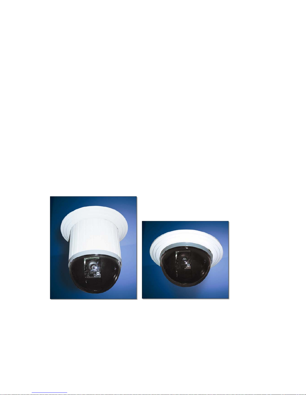
z Flexible Mounting: Indoor-embedded and attached types; Outdoor-with weather resistant housing
UNC7825-O & UNC7825-OW Common Features
z Auto Focus Lens: built-in 25X optical zoom lens with focal length 3.8 ~ 95.0mm
z True Day & Night Camera: Color / Mono Switch (IR Cut Filter)
z 570 TV Lines Mono Resolution, 480 TV Lines Color Resolution
z 0.01 Lux Sensitivity (Mono), 0.1 Lux Sensitivity (Color)
z Auto Focus Modes Selectable
z Manual Iris Speeds Selectable
z Back Light Compensation Zone Selectable
z Gamma Adjustment
z On-Screen Setup Menu
- 5 -
Page 7

UNC7825-OT
z Auto tracking movement.
UNC7825-O
z Aperture Correction Adjustment
UNC7825-OW
z 2.56X Digital Zoom: For a total of 64X combined digital and optical zoom.
z Wide Dynamic Range: Uses two Shutter Speeds in alternative video fields and combines two fields into one
progressive scan frame. As a result, combined field yield a frame of high-quality image.
z Dynamic Privacy Zone: With this function, unwanted or prohibited areas within an image can be masked
appropriately.
z Preset Scene File: Preset setting such as BLC, AE mode, Shutter speed and AF mode can be saved as Scene
File and apply to other presets with similar circumstances to improve efficiency.
z Slow-speed Shutter
z Image Memory Function: Horizontal/Vertical Flip, 180
o
Image Rotation, Field Image Capture.
- 6 -
Page 8
1 Physical Connections
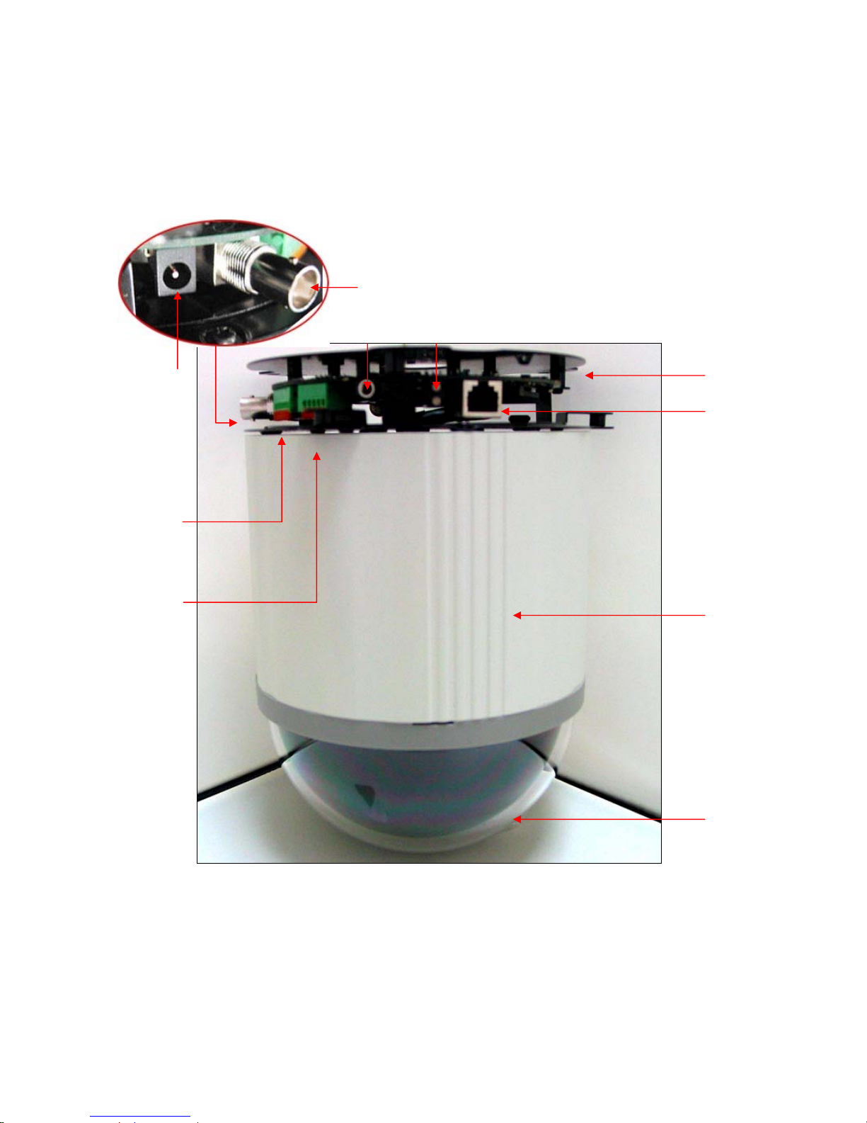
1.1 Structural Element
9
8
7
5
6
4
10
3
2
1
1. Dome Cover 6. Video In /Out Jack
2. Camera Case 7. Power In Jack
3. Ethernet Port 8. Alarm In/Out Jack
4. Power / Network Status LED 9. RS-485 In/Out Jack
5. Audio Line In Jack 10. Camera Base
- 7 -
Page 9
1.2 Connection Jack and Cable Requirement
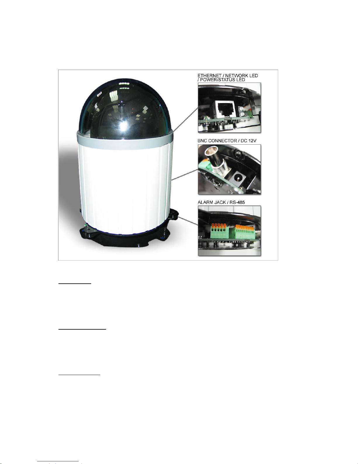
Power In Jack
z DC12V Input Voltage, Power Consumption 1.2Adc, Center Pin 2.0mm
z Require Cable: 18 AWG x 2C
Video Out BNC Jack
z Video Signal Output CVBS 1.0Vpp 75Ω BNC
z Recommend Data Cable:5C2V
Alarm In/Out Jack
z Each NDC contains 6 alarm inputs and 1 alarm output
z Alarm Input Voltage 5.6V max, Output 0.5A 120Vac/ 1A 24Vdc
z Recommend Data Cable: UL 26 AWG 80 C 300V UL 24 AWG 80 C 300V
- 8 -
Page 10
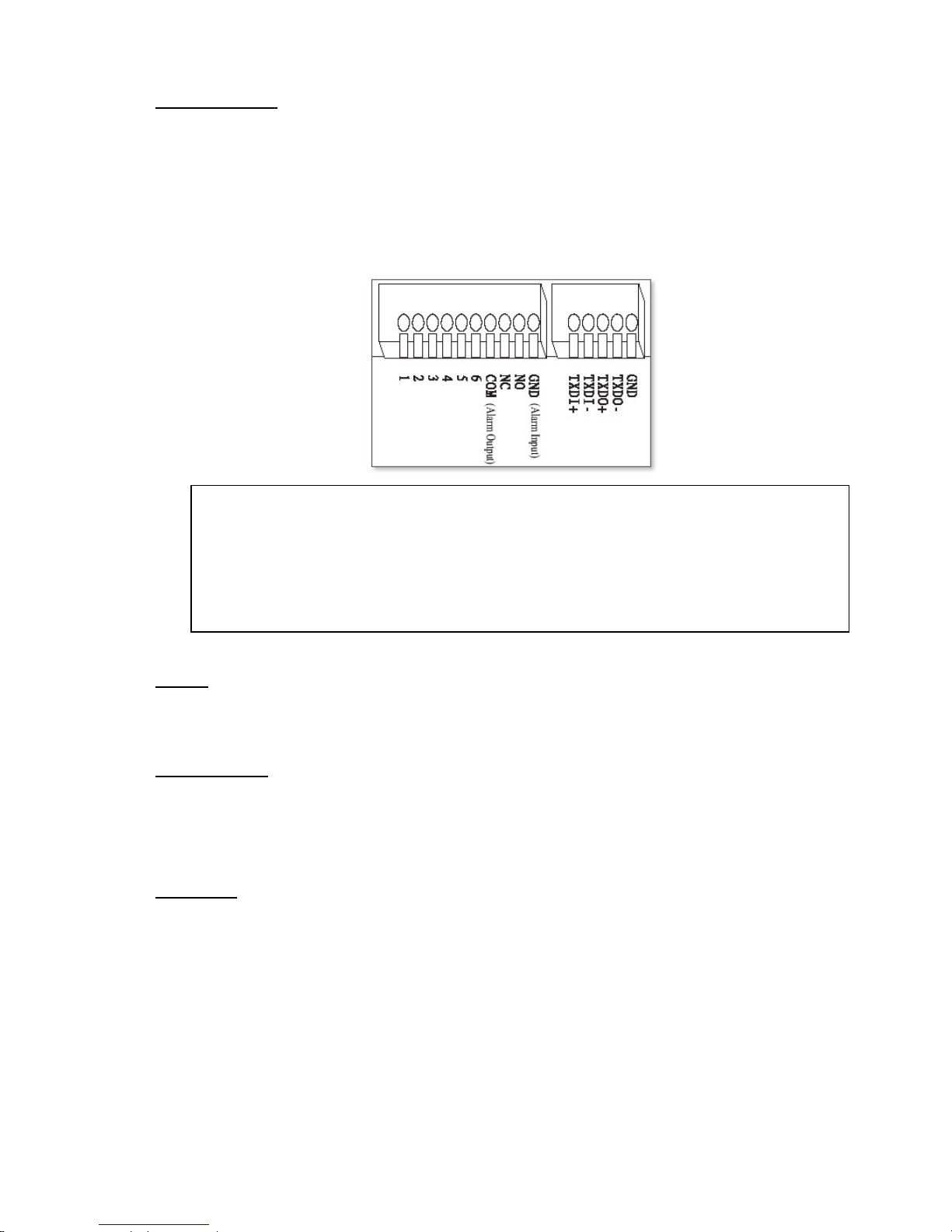
RS-485 In/ Out Jack
z RS-485 Input (TXDI+, TXDI-) to receiver signal from keyboard, matrix, DVR or multiplexer through twisted pair
cable.
z RS-485 Output (TXDO+, TXDO-) sending out signal to next NDC through twisted pair cable.
z Recommend Data Cable: 2547 VW-ISC UL 24 AWG x 2C
z Transmission Distance: Max. 1 Kilometer
* When 24VAC PSU is used, the recommend cables are:
z UL SPT-1 VW-1 18AWG x 2C
z UL SPT-2 VW-1 18AWG x 2C
z UL SUT 105C VW-1 18AWG x 3C
The distance between 24Vac PSU and fast dome cannot exceed 200 meters.
Ethernet
z Standard IEEE 802.3 10 /100 Base-T port
Power/Status LED
z Power On: constant red.
z Emergency factory default (appendix C): Blinking orange (i.e. red mix with green).
Network LED
z Network Link (connected): Constant red.
z Networks have activities: Blink red.
z Data sent out from server: Blink green.
z Network disconnected: Constant slow blinking green.
z Upgrading software (appendix A): Constant slow to fast blinking of orange.
- 9 -
Page 11
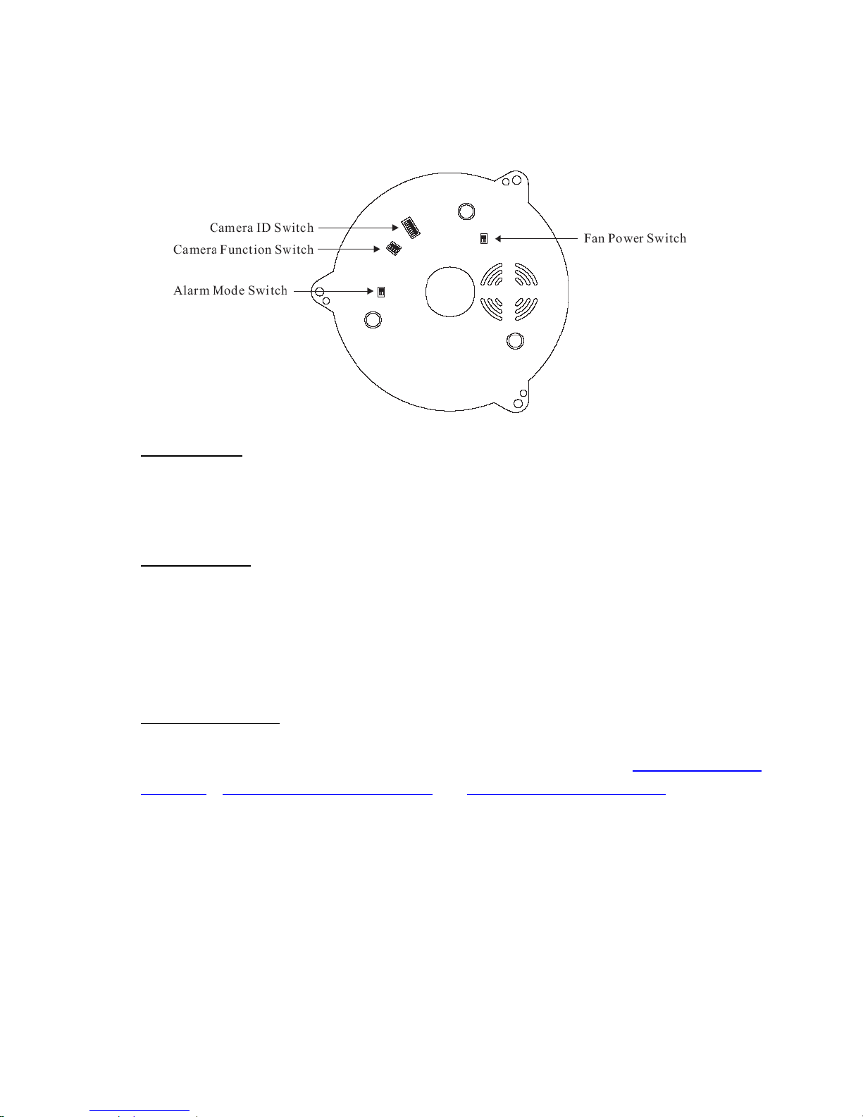
1.3 DIP Switch Setting
Fan Power Switch
Turn the number 2 switch to ON position to activate the internal fan. This will maintain the temperature inside and
make electric parts life.
Alarm Mode Switch
Alarm Mode can be set as Lock or Release mode. Turn number 1 switch to ON position to choose Release mode.
Turn number 1 switch to OFF position to choose Lock mode. The NDC has 6 alarm inputs and 1 output, which
can be set either NC (normally close) or NO (normally open) mode. Turn number 2 switch to NO position to
choose NC mode. Turn number 2 switch to OFF position to choose NO mode.
Camera Function Switch
For UNC7825-O, UNC7825-OW (25X optical lens model) and UNC7825-O T, please refer to “5. Advanced Settings for
UNC7825-O”, “6. Advanced Settings for UNC7825-OW” and “7. Advance Settings for UNC7825-OT” for details.
- 10 -
Page 12
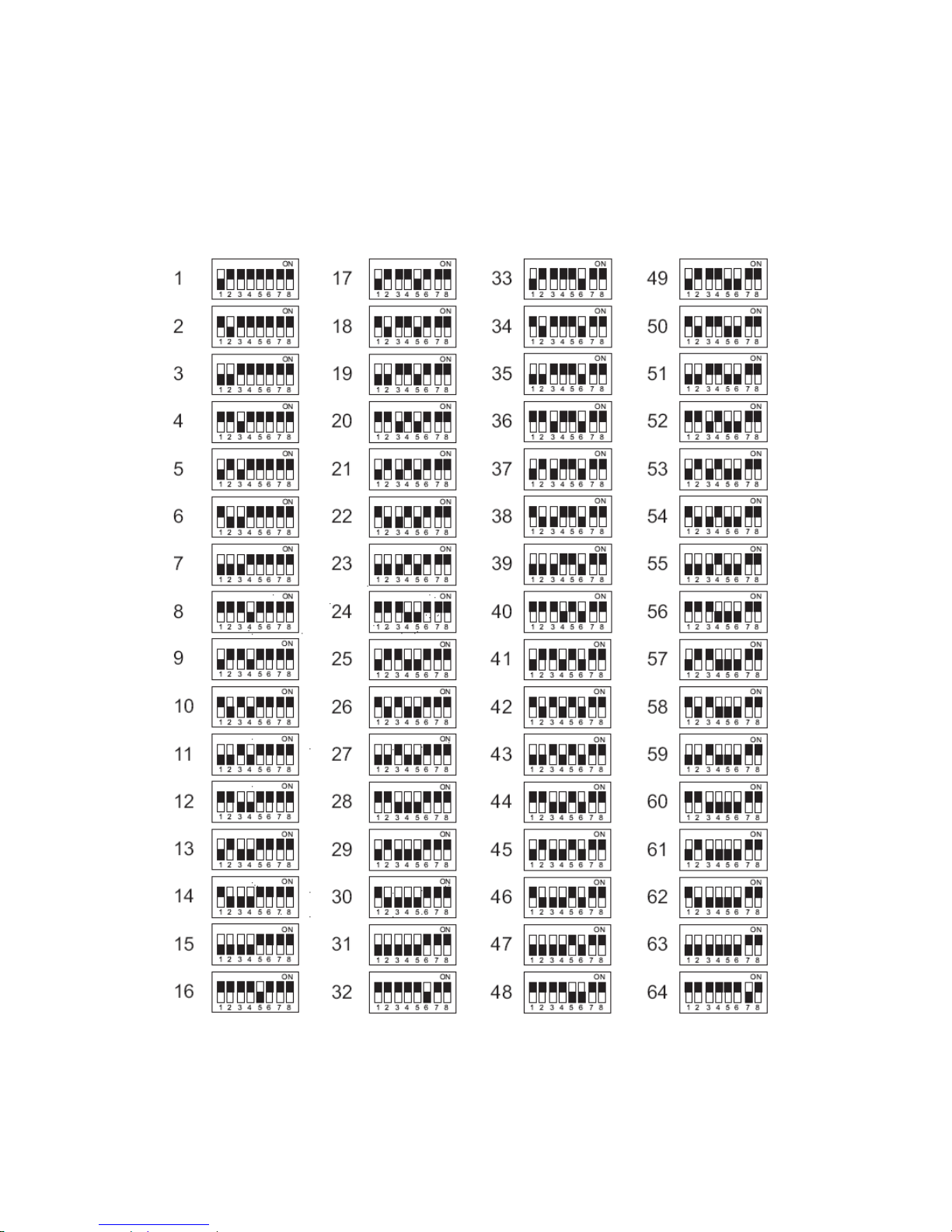
1.4 NDC ID Address Setting Refer Chart
Up to 64 NDC can be serial linking in one system. Therefore each dome is addressing by ID switch located at the base
of the NDC. Below is the address setting for camera 1~64:
- 11 -
Page 13

2 Installation
2.1 Installation Preview
There are 3 mains steps required to perform a successful installation:
z Hardware installation
z Software installation
z Network configuration
Hardware installation consists of connecting cables to the NDC including network, video, and power cables.
Software installation consists of the installation of software that is necessary to properly view the video from the NDC
or to configure the NDC itself. The software includes:
z IP Installer -- a utility for locating devices and configuring network settings on a LAN.
z Component Installer -- installs all ActiveX components used by the device for things such as video display and
configuration.
z Macromedia Flash Player -- necessary for displaying some components of the Web UI.
The following are not necessary, but may be used for convenience:
z Recording Software -- displaying and recording up to 16 channels simultaneously. Both the MPEG-4 and MJPEG
devices are supported.
z Xvid -- a MPEG-4 codec. If no other MPEG-4 codecs (ie. DivX, 3ivX, ffdshow, etc.) are installed on your computer,
the Component installer will install this for you.
z QuickTime or VLC -- though not necessary, this can be used for viewing the MPEG-4 stream without a Web
browser.
Network configuration consists of modifying the network settings for the NDC in order to successfully connect to the
device.
- 12 -
Page 14
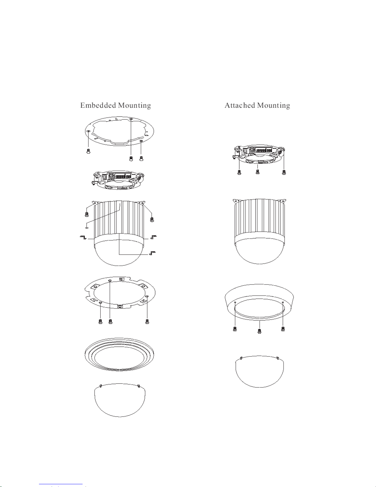
2.2 Hardware Installation
– Indoor Installation Structural Drawing
- 13 -
Page 15
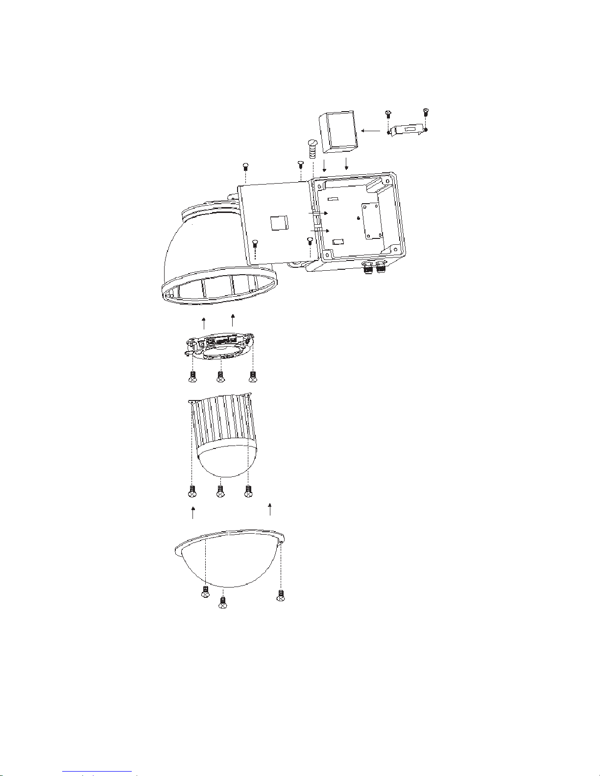
– Outdoor Installation Structural Drawing (Pendant Mounting)
- 14 -
Page 16
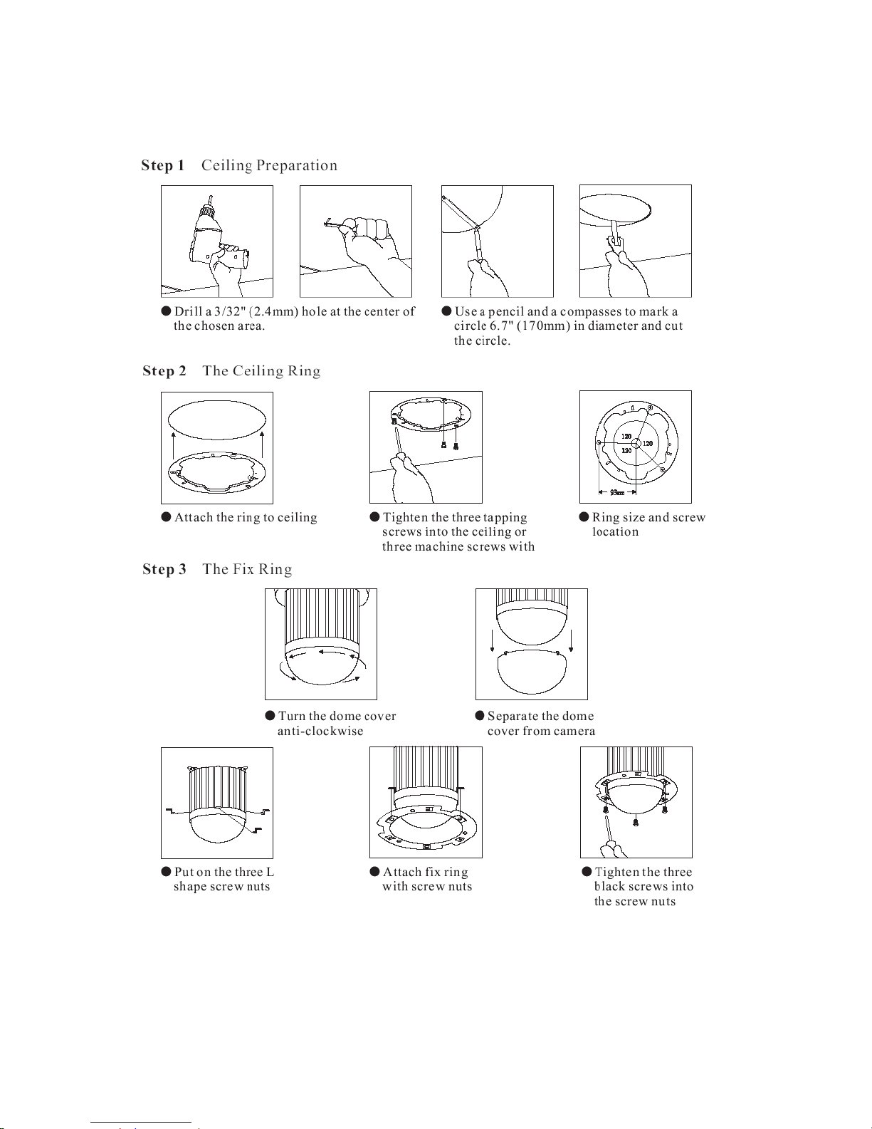
– Embedded Mounting (False Ceiling)
- 15 -
Page 17
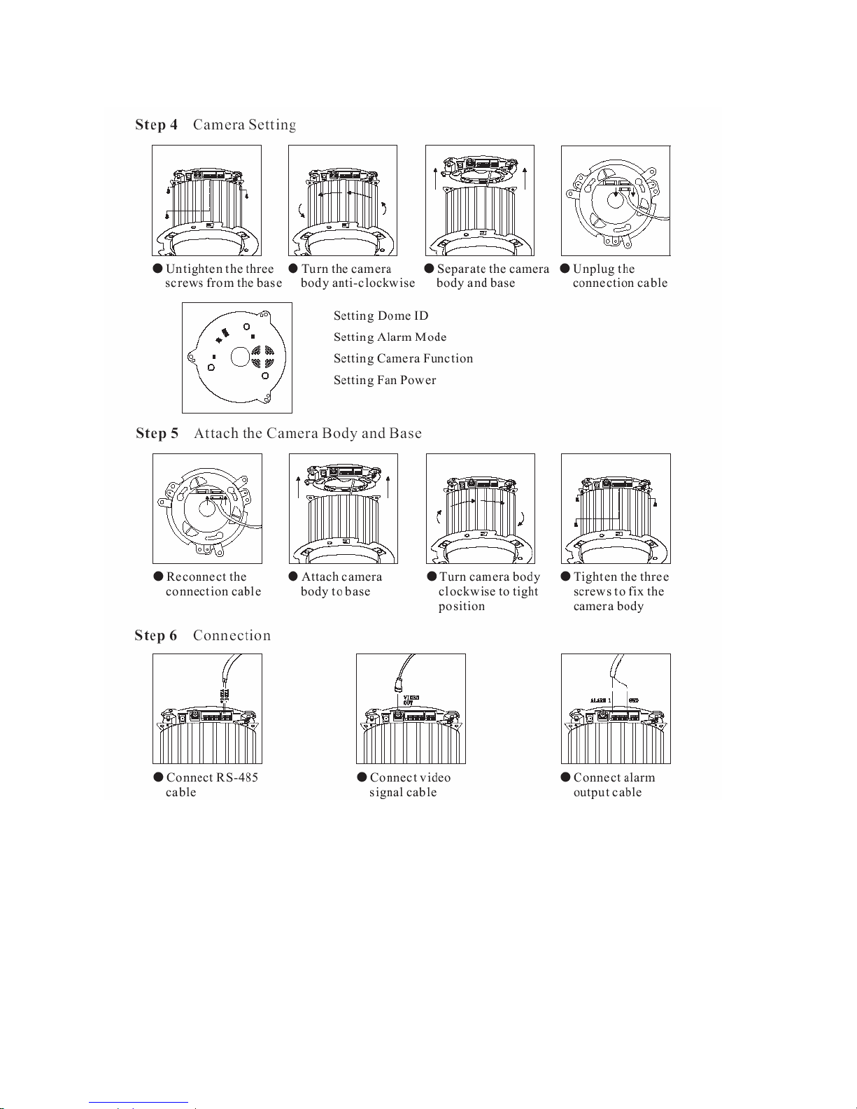
- 16 -
Page 18
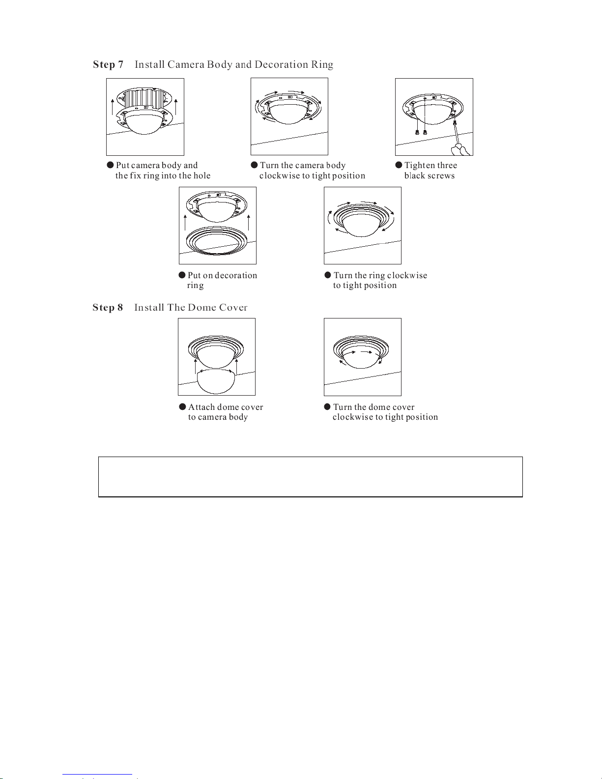
Note: After dome cover is attached, use glass-cleaning cloth to clean dome cover. Unclean dome cover may
affect camera performance.
- 17 -
Page 19
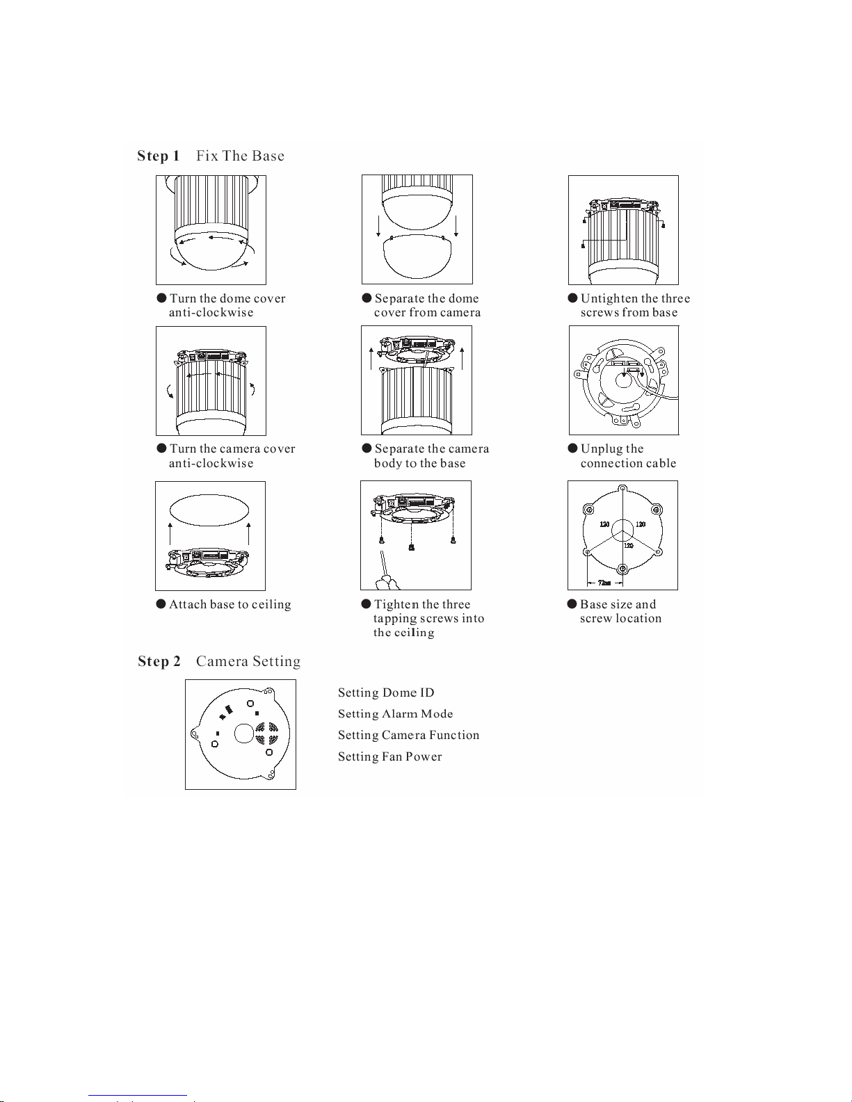
– Attached Mounting (Fixed Ceiling)
- 18 -
Page 20
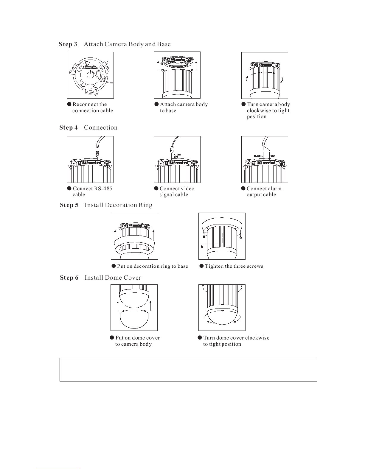
Note: After dome cover is attached, use glass-cleaning cloth to clean dome cover. Unclean dome cover may
affect camera performance.
- 19 -
Page 21
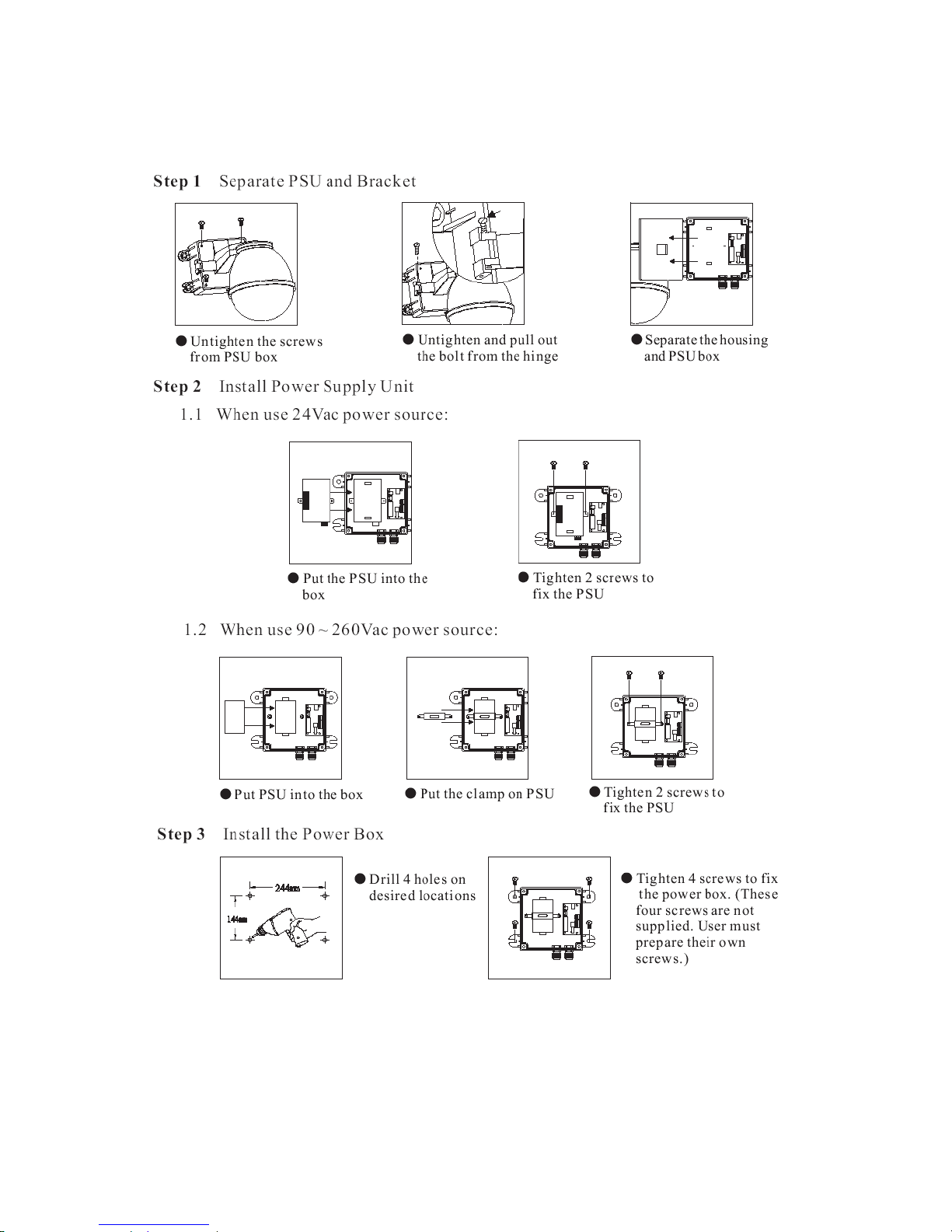
– Pendant Mounting (External Housing)
- 20 -
Page 22
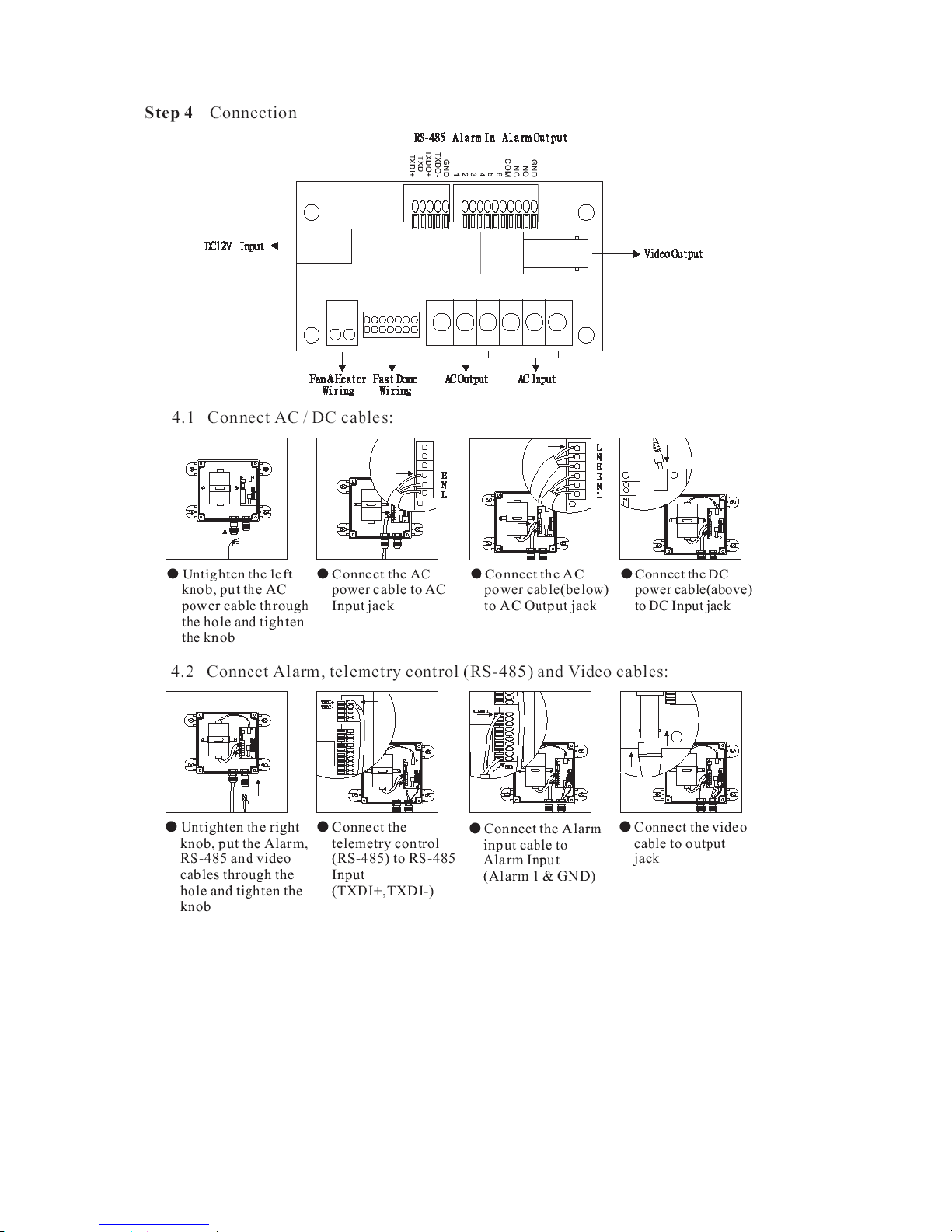
- 21 -
Page 23
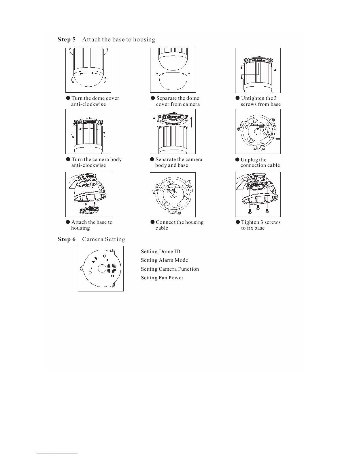
- 22 -
Page 24
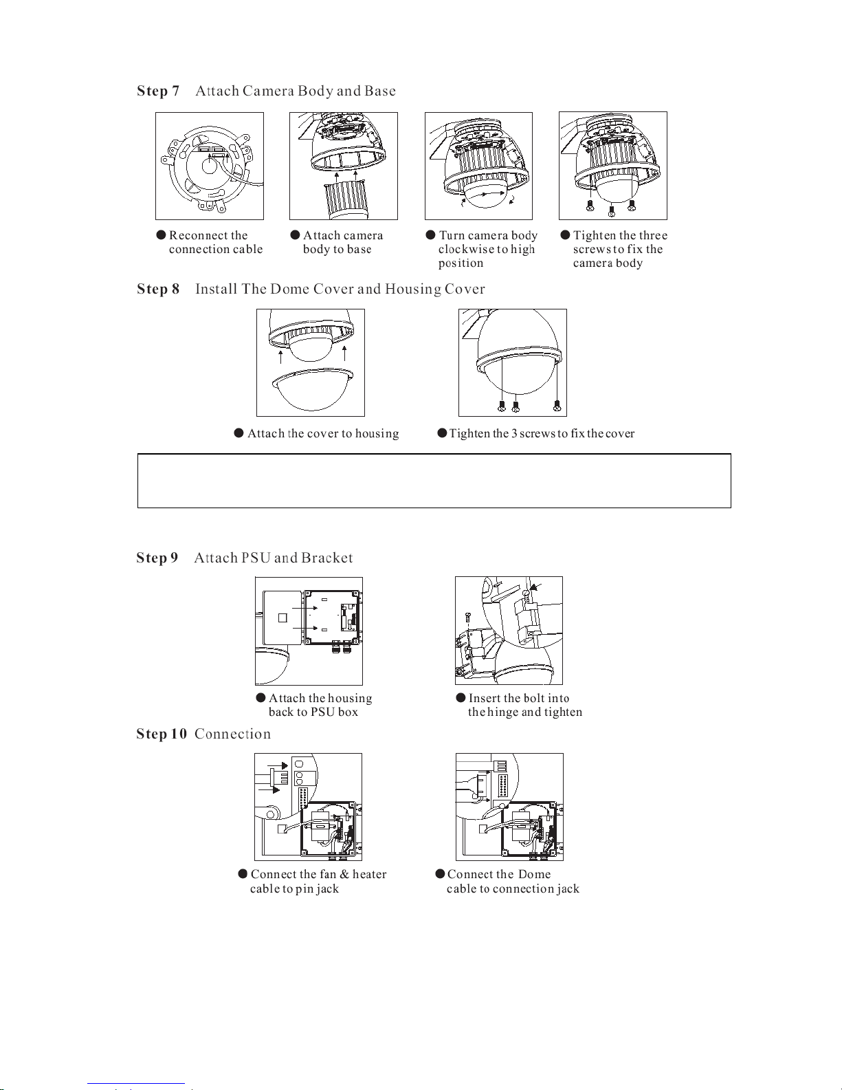
Note: When the NDC is installed inside outdoor housing, please don’t attach dome cover. Violation may affect
camera performance.
- 23 -
Page 25
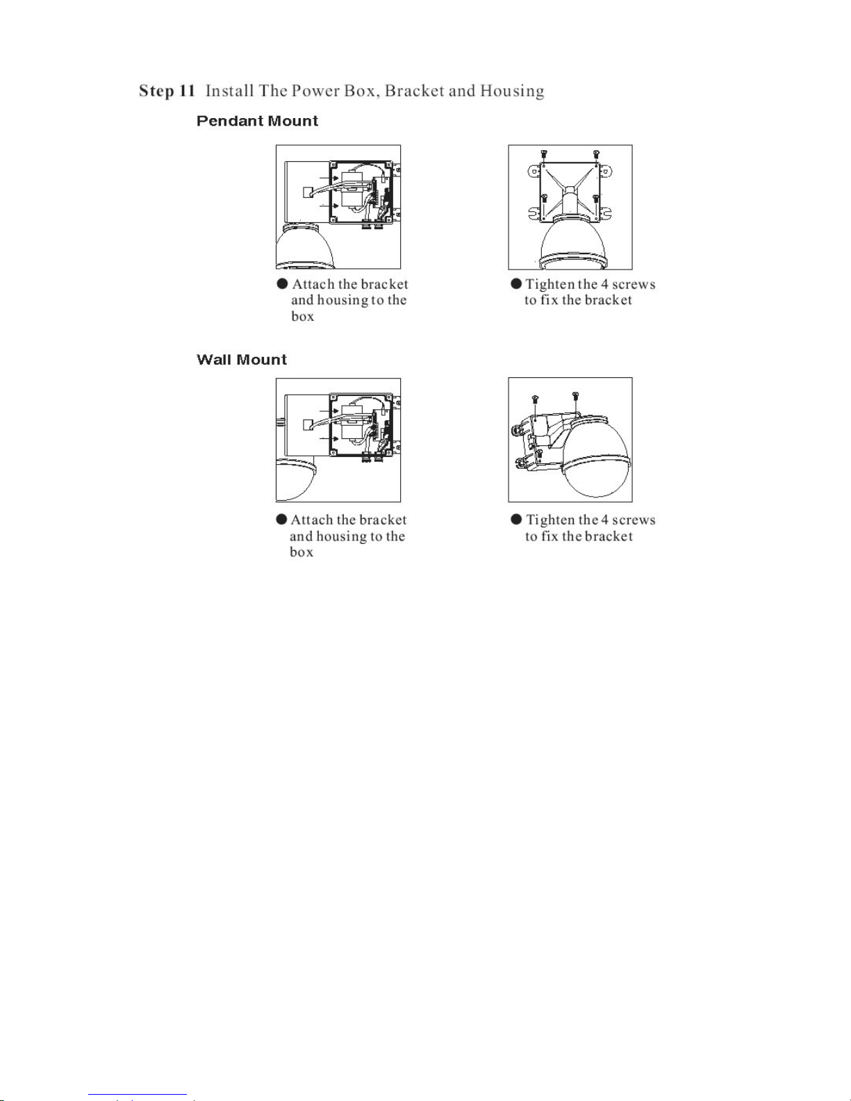
- 24 -
Page 26

2.3 Software Installation
With the exception of the Macromedia Flash Player all the software that is necessary for the proper display and use of
the NDC is available on the included CD or from the Web site. For the following installation procedures it is assumed
that all installation media will be taken from the CD.
IP Installer
The IP Installer is used to locate and configure network cameras and video servers on the LAN. This utility is
useful for conveniently configuring the network settings of the NDC, or for finding a device once the network
settings have been modified.
To install the IP Installer, from the installation CD UI, select IP installer, then follow the on screen instructions.
Component Installer
This will install all ActiveX components used by our devices for video display and device configuration.
Adobe Flash Player
Please visit the Macromedia Web site at http://www.adobe.com/downloads/ to download and install the Flash
Player.
- 25 -
Page 27
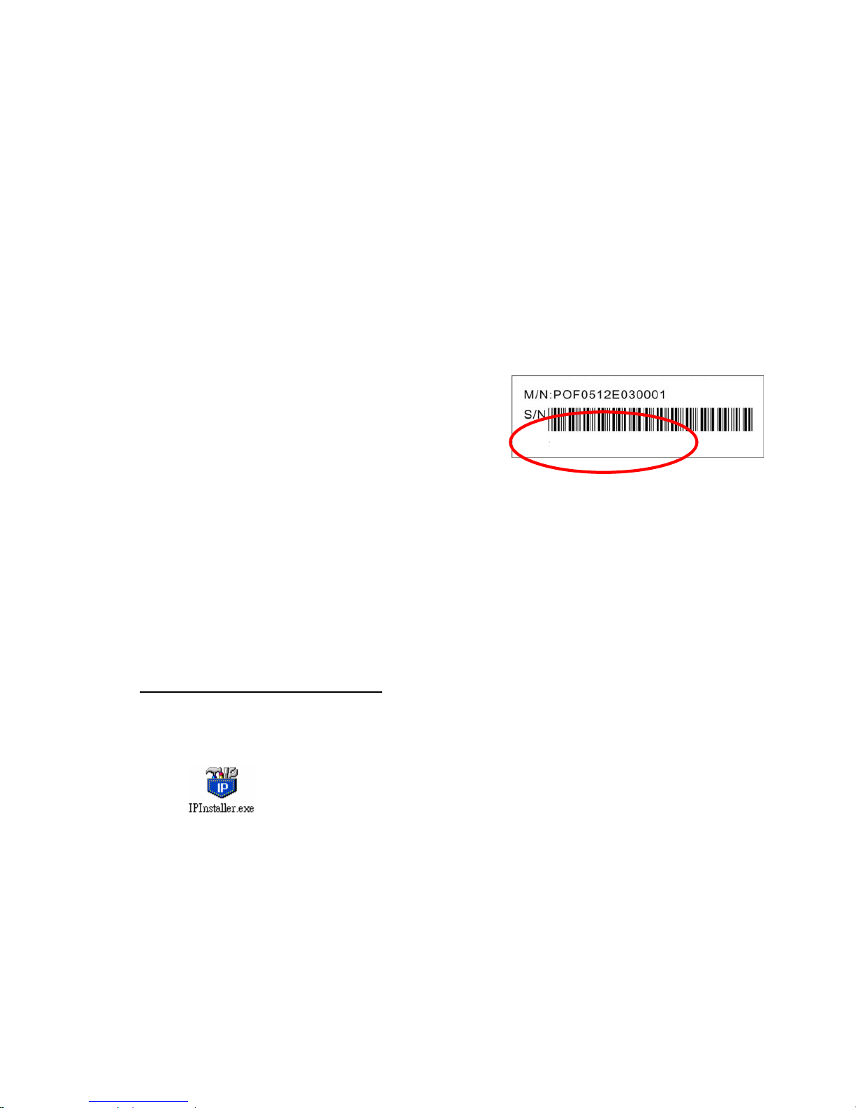
2.4 Network Configuration
IP Installer is a utility that provides an easier, more efficient way to configure the IP address and network settings of the
NDC. It even provides a convenient way to set the network settings for multiple devices simultaneously using the batch
setting function. Moreover, IP Installer can save the network settings for all devices as a backup and restore them
when necessary.
– Preparation before IP Assignment
z Always consult your network administrator before assigning an IP address to your server in order to avoid using a
previously assigned IP address.
z Ensure the NDC is powered on and correctly connected to the
network.
*000429000094
z MAC Address: Each NDC has a unique Ethernet address (MAC
address) shown on the bottom of the NDC as the serial number
(S/N) with 12 digits (e.g. 000429-XXXXXX).
z One final note, although the IP Installer is able to find and configure any NDC on the LAN except those that are
behind a router, it is a good idea to set the host PC to the same subnet. In order to connect to the Web-based user
interface of the NDC, the host PC must be in the same subnet. For more information about subnets, please
consult your network administrator.
– Using IP Installer
Assigning an IP Address to NDC
1. Once IP Installer has been successfully installed on the computer, double click the IP Installer icon on the
desktop, or select it from Start > Programs> IP Installer > IP Installer.
2. The IP Installer window is displayed below.
3. Click the menu bar Tool > Search Network Device to search the NDC in the LAN.
- 26 -
Page 28
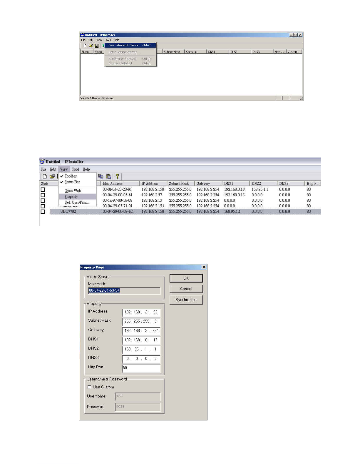
4. From the list, select the device with the MAC Address that corresponds to the device that is to be configured.
The MAC Address is identical to the unit’s S/N (Serial Number).
5. Double click the item to open the Property Page dialog box for the selected device or click the menu bar View
> Property.
6. After filling in the properties, click [Synchronize] button to complete the configuration settings in the remote
NDC while saving configuration in the PC.
If click [OK] button, the configuration is only be saved in the PC.
- 27 -
Page 29
Opening the Web-based UI of the Selected NDC
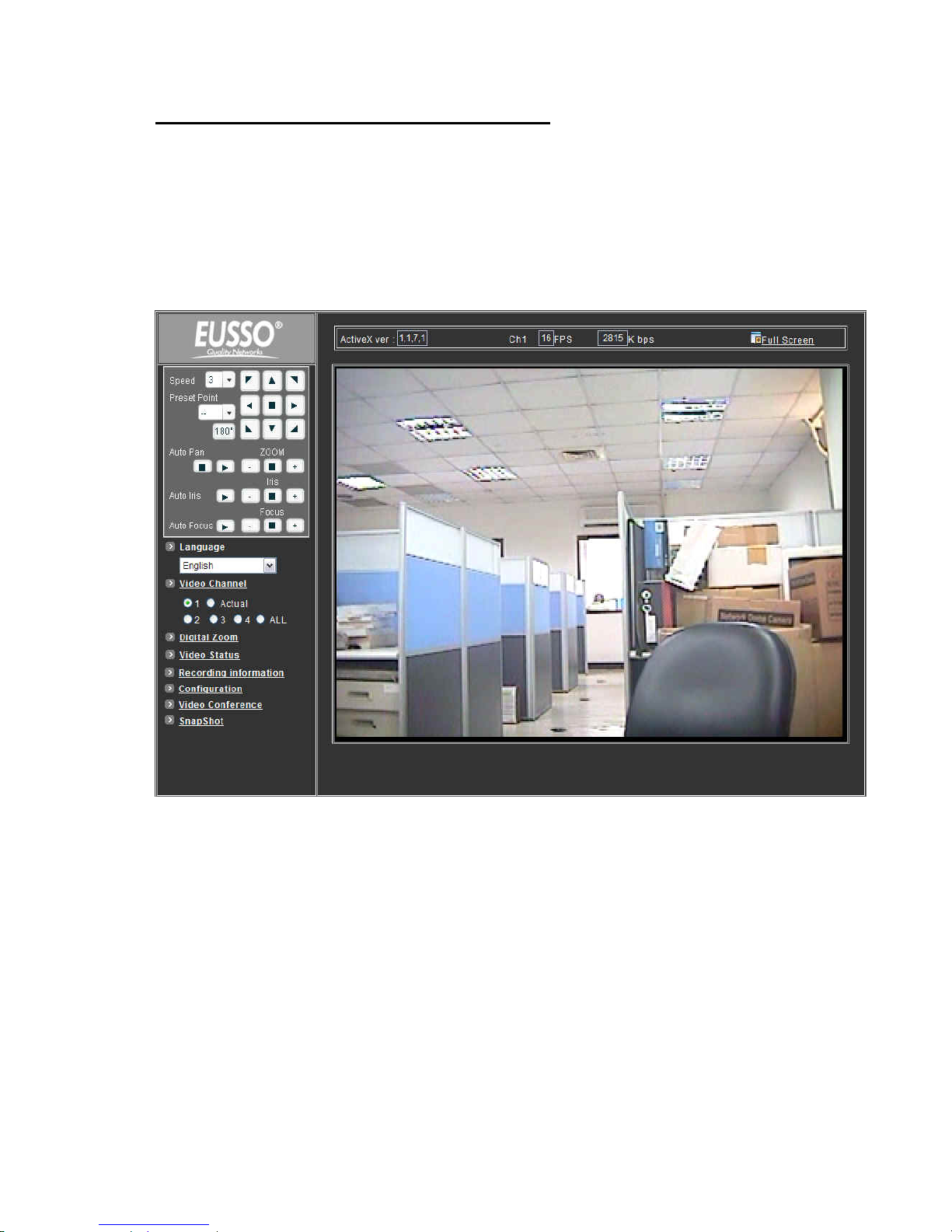
1. To access the Web-based UI of the selected unit, run the View > Open Web on IP installer menu bar.
2. If the device has been configured correctly, the default Web browser will open to the home page of the
selected device.
3. If you find your browser is opened and automatically connected to the NDC Home Page, it means you’ve
assigned an IP Address to the unit successfully. Now you can close the IP Installer and start using your NDC.
- 28 -
Page 30

Verify and Complete the Installation from Your Browser
Start your browser and enter the IP Address of your NDC in the Address field.
The NDC can support Microsoft Internet Explorer
TM
and NetscapeTM. But the voice feature can only be run under
Microsoft Internet ExplorerTM.
When browsing the Home Page at the first time with the Microsoft Internet Explorer
TM
, you must temporarily lower
your security settings to perform a one-time-only installation of the ActiveX component onto your workstation, as
described below.
1. From the Tools menu, select [Internet Options]
2. Click the [Security] tab and then click [Custom Level] button to see your current security settings.
3. Set the security level to Low and click [OK].
4. Type the URL or IP address of your NDC into the Address field.
5. A dialog box will pop up asking if the ActiveX control should be installed. Click [Yes] to start the installation.
6. Once the ActiveX installation is complete, return the security settings to their original value, as noted above.
- 29 -
Page 31
3 Usage of Web-based User Interface
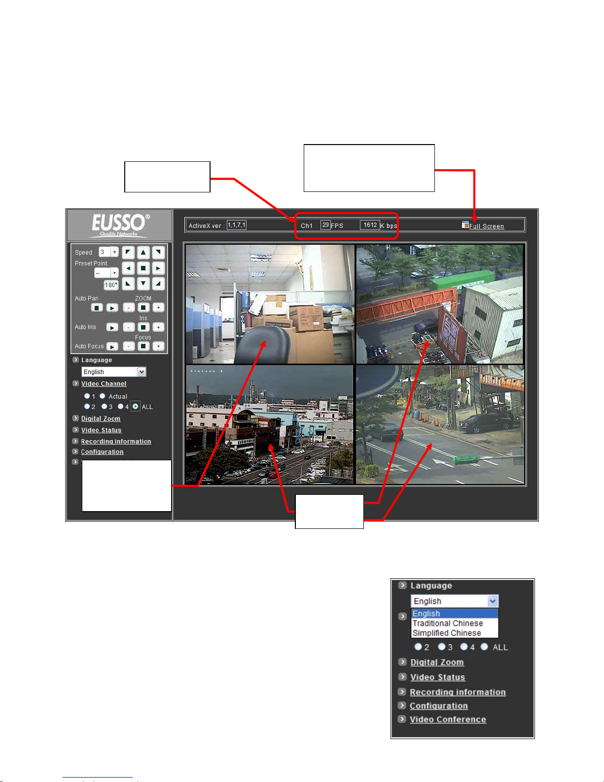
Start your Web browser and enter the IP Address of your NDC Camera in the Address field. The Home page of the
camera is now displayed. The Web UI can present up to 4 video source indicating 4 video channels. Each channel can
be shown individually or in one of 4 split windows.
The status of the
video stream
Full Screen
Maximizes to view the selected
channels into full screen
1
3
Video stream from
camera (Local video
source)
4
2
External video
sources
3.1 Browse Live Video
– Menu Language Selection
The online Web-based User Interface can allow the user to select 3
different languages: English, Traditional and Simplified Chinese.
Such display will not affect the original configuration for the language,
allowing multiple users to have different languages concurrent views. In
order to make the language change permanent, settings must be modified
through the Configuration page, and saved once it is made.
- 30 -
Page 32
– Video Channel Selection
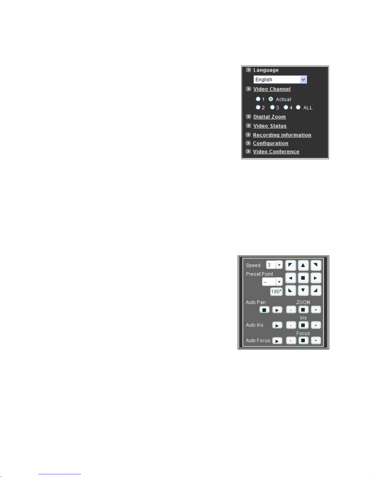
The Video Channel allows the users to choose viewing 1 channel at a time or
4 channels at the same time.
CH1 displays the video stream of the NDC.
CH2~4 display the video stream of the IP Camera or Video Server that
connected the device via network.
z Select “All” to display the local video stream (Channel 1) as well as 3
external video sources (Channel 2 ~4).
z Select 1~4 to display the video stream of single channel.
z Select Actual to display the video stream at the actual resolution.
– Pan / Tilt / Zoom Control
The PTZ control panel allows the users to pan, tilt and zoom the dome.
z Speed : Click on the arrow button and select the speed of the Pan and Tilt movements. Values run from 1 to 7.
Being 1 the slowest and 7 the fastest.
z Preset Point : Click on the arrow button and select the preset point from the pull-down list for quick view.
z Manual Pan/Tilt : Click on the 8-directions button to move the camera to that direction. Click on the rectangle
button to stop the movement.
z 180
o
button : The viewing will turn 180 degrees.
z Zoom - : Click on this button for Zooming Out.
z Zoom + : Click on this button for Zooming In.
z Iris + : Opens the iris and brightens the picture.
z Iris - : Opens the iris and reduces glare.
z Focus + : The target will become nearer.
z Focus - : The target will become farther.
z Auto Iris : The lens will automatically adjust itself for optimum iris.
z Auto Focus : The lens will automatically adjust itself for optimum focus.
z Auto Pan : Click on the arrow button to activate; click on the rectangle button to stop. When the Auto Pan function
is activated, the NDC will auto touring the preset groups entered. Only the first 16 preset points of the NDC can be
set to auto pan mode and first 6 preset points are corresponding with the 6 alarm.
- 31 -
Page 33
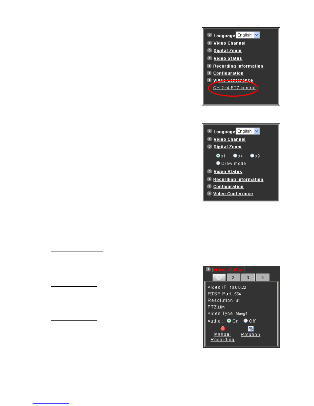
To pan/tilt/zoom the external video sources CH2~CH4, click on [CH2~4
PTZ Control] button to open a new window. Select the channel in this
window to display the PTZ control panel for operation.
– Digital Zoom Selection
The Digital Zoom enable user to select the digital size for the channels.
z Select [x1], [x4] or [x9] to enlarge the video.
z Select [Draw Mode] and then use mouse to select an area on the
video for enlargement.
– On/Off the Audio, and Rotate the Video
The [Video Status] item allows the users to see the current settings of the selected channel. It also includes the
function for audio control, video rotation and record the video/audio for the selected channel.
Select the Channel
Click on the number tab, and status for the selected channel will be displayed. The settings can be setup in
Configuration page.
On/Off the Audio
Select [On] or [Off] button to enable or disable the audio for selected
channel.
Rotate the Video
Click on [Rotation] button to temporary rotate the selected video 90
degrees clockwise direction. This feature is to have natural view for
cameras that are hooked up on walls and/or vertical positions.
- 32 -
Page 34
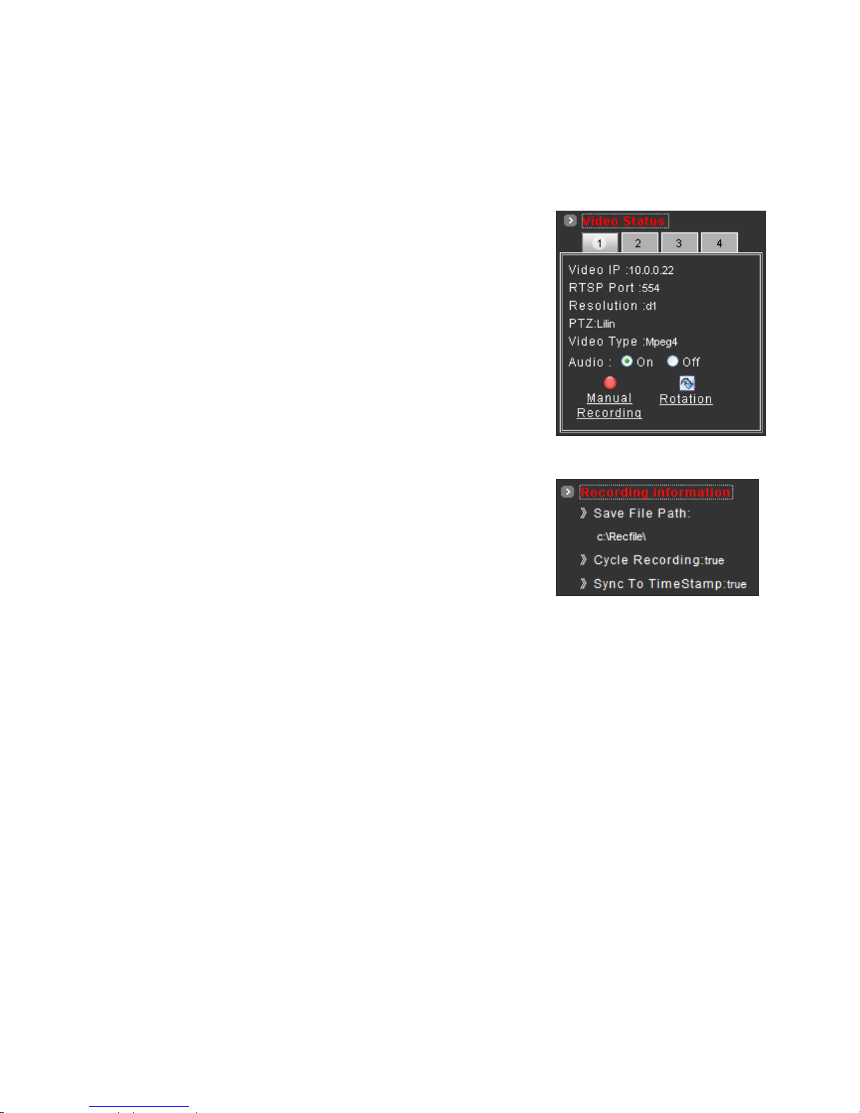
3.2 Video and Audio Recording
Before recording the selected channel, you can check the information of recorded file by clicking on [Recording
Information] item. The settings can be changed in Video Conference page.
z To record the video and audio for each channel:
1. Click the channel number on the tab under [Video Status].
2. Click on [Manual Recording] button, it will start recording live v
and audio of the selected channel. A “REC” message will display o
the video.
ideo
n
cord
isappear
3. The device can record multiple channels at the same time. To re
other channels, just repeat step 1 and 2.
4. To stop recording, select the channel from the tab and then click
[Manual Recording] button again, the “REC” message will d
and the recording is stopped.
z By default, the recorded file will be saved in a folder named
C:\Recfile\CHx\
♦ x : The number of the recorded channel
z The default filename will be named under Locals_Rec-
yyyymmdd-hhmmss.avi
♦ yyyy : Current Year
♦ mm : Current Month
♦ dd : Current Date
♦ hh : Current Hour
♦ mm : Current Minute
♦ ss : Current second
z The file will be saved as an AVI file, which can be play back with most media players.
z The video is always recording with the actual direction. It will not be affected by the rotation of viewing.
- 33 -
Page 35
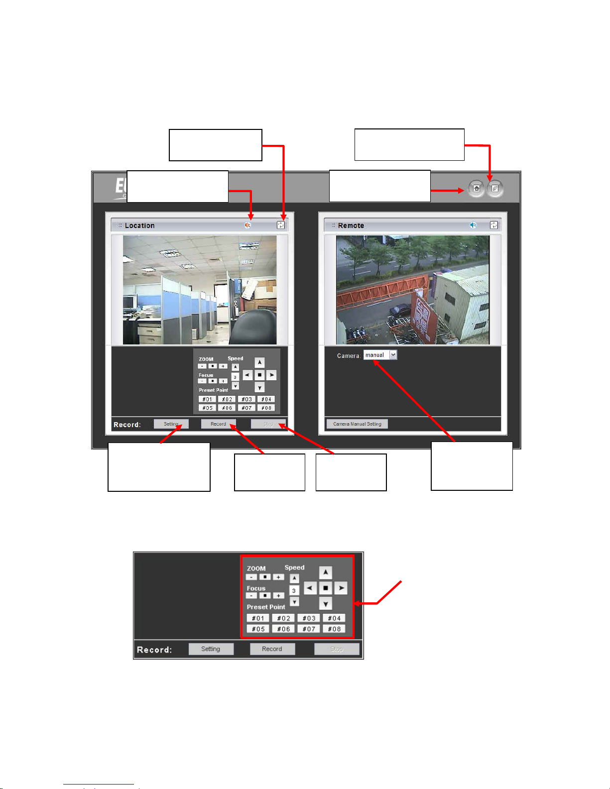
3.3 Video Conference
Click [Video Conference] to open the conference page.
Click this button backs to
the Home page
Click this button to open
the Configuration page
On/Off the audio of this
video stream
Rotate this video for
viewing
Record
Start recording
Stop
Stop recording
Setting
Configure the settings for
Recording
Camera
Select the remote
device
– Control the Video in Location Window
To control the dome camera, use the buttons on the PTZ Control panel to pan, tilt and zoom the camera.
PTZ Control
z Zoom - : Click on this button to Zooming Out.
z Zoom + : Click on this button to Zooming In.
- 34 -
Page 36
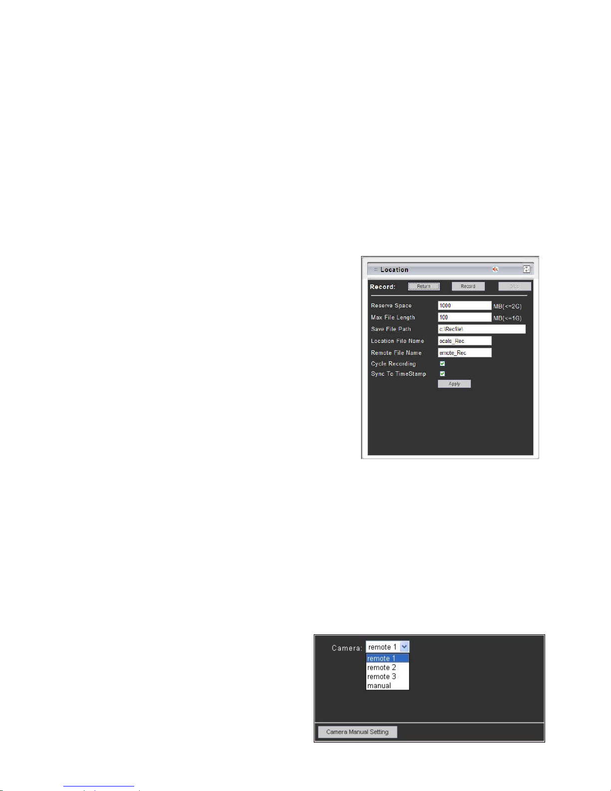
z Focus + : The target will become nearer.
z Focus - : The target will become farther.
z Speed : Click on the UP/Down arrows and select the speed of the Pan and Tilt movements. Values run from 1 to 7.
Being 1 the slowest and 7 the fastest
z Manual Pan/Tilt : Click on the 4-directions button to move the camera to that direction. Click on the rectangle
button to stop the movement.
z Preset Point : Click on the number buttons to select a preset position for quick view.
– Setting for Video Record
You can change the settings for recording by clicking on [Setting] button in Location window.
z Reserve Space : Set the total file space for the recording.
z Max File Length : Set the file space that a single file will be
using.
z Save File Path : Indicate which folder should the file be saved
to.
z Location File Name : Input the name for the file that recorded
from the location device.
z Remote File Name : Input the name for the file that recorded
from the remote device.
z Cycle Recording : This feature determine if the old space
should be used or not for the recording. Make a check mark
in order to enable this function. If you enable this feature, old files will be deleted
z Sync to TimeStamp : This feature enables the file to be saved according to the time. When the video file is
displayed, the video will make a match between the frames and the time.
z Apply : Click this button to save the changes made.
z Return : Click this button returns to the live video of the location device.
z Record/Stop : Click [Record] button to start recording. Click [Stop] button to stop recording.
– Select the Remote Device
Select the camera from the pull-down list, the video of
the remote device will be displayed.
There are 4 cameras can be selected as the Remote
device. The first three are set up in the Configuration
page; the last one can be set up by clicking [Camera
Manual Setting] button.
- 35 -
Page 37
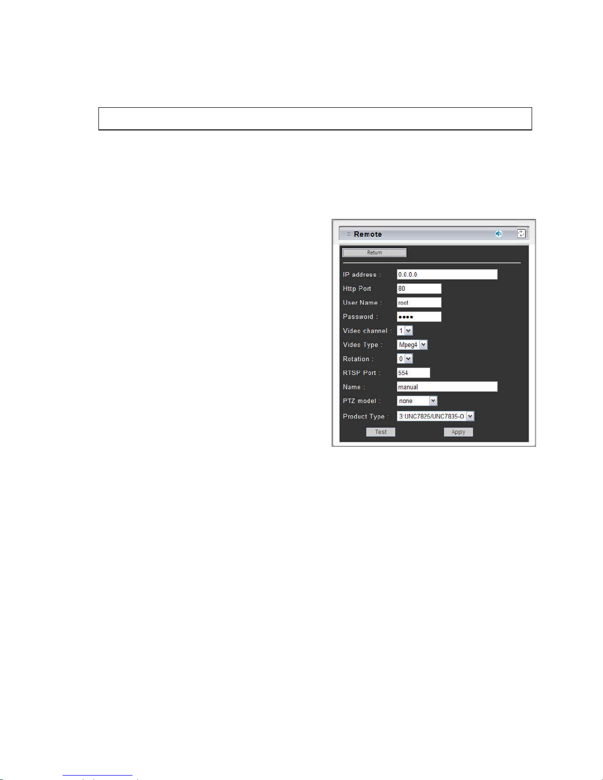
– Manually Set Up Additional Camera
This feature allows the user to temporary set an additional video source for the remote device.
Click on [Camera Manual Setting] button on the Remote window, and configure the following settings:
Note: This camera will be removed after leaving or closing the Web page.
z IP address : Enter a valid IP address from an IP Camera or Video Server.
z Http Port : Enter the port number used for the IP address for network connection.
z Username/Password : Enter the respective Username
and Password if applicable. If no user has been set for
the device, the default value should be root and pass
respectively.
z Video Channel : If the selected camera is connected
to a Video Server, select the channel of the Video
Server.
z Video Type : Select MJPEG or MPEG4. The type must
match the external source provided.
z Rotation : Rotate the video for view. Rotation degrees
run from 0 to 270 degrees.
♦ 0: 0 degree
♦ 1: 90 degrees
♦ 2: 180 degrees
♦ 3: 270 degrees
z RTSP Port : Enter a RTSP Port used for streaming in case the external source is a MPEG4 device.
z Name : Enter a name for the device.
z PTZ Model : Enter a PTZ model.
z Product Type : Select from MJPEG, MPEG4 Video Servers or IP Cameras. Please refer to the original document
of the device for a better description.
z Test : Before submitting the information, click on this button to validate the video connection and the live video will
be displayed if the settings are correct.
z Apply : Click this button to save the changes made.
z Return : Click this button returns to the live video of the remote device.
- 36 -
Page 38
4 Configuration of Web-Based User Interface
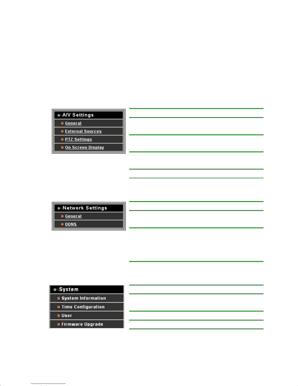
The Configurations of the NDC are presented as links in the margin of the Configuration Page. Simply click the
relevant link for the settings you want to configure.
4.1 Configuration Preview
A/V Settings
Functions Description
General Set the parameters of video and audio, and adjust
the image of the device.
External Sources Set the video source for channel 2 to 4, using
digital inputs (IP Address).
PTZ Settings To control the PTZ device and set the preset
points.
On Screen Display Set the text and location to display on the video.
Network Settings
Functions Description
General Assign an IP Address and configure the relevant
network parameters to the device.
DDNS The DDNS (Dynamic Domain Name Service) is
used to access the NDC with an easy memorized
name such as http://demo.ddns.com instead of
http://192.168.0.200.
System
Functions Description
System Information Set various information about the name of the
device and the language type, etc.
Time Configuration Set the Date and Time.
User Add and delete users and passwords.
Firmware Upgrade Browse firmware location for upgrading
- 37 -
Page 39
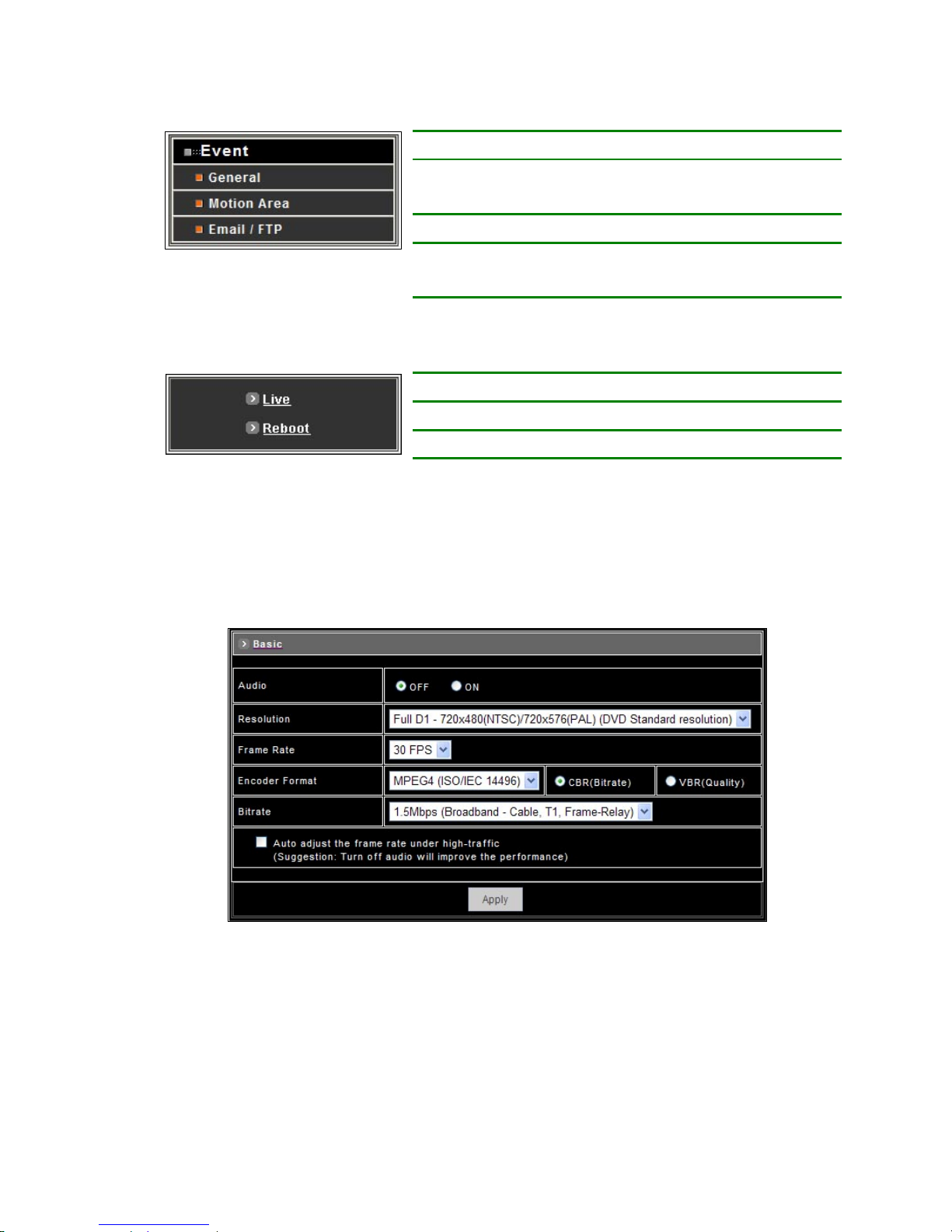
Event
Functions Description
General Enable/disable the event trigger and select the
action when triggered.
Motion Area Set the area on video for motion detection.
Email / FTP Input the Email and FTP address to receive alert
message or snapshot, sent by event trigger.
Others
Functions Description
Live Returns to the Live Video display.
Reboot Close the Web browser and reboots the device.
4.2 Configuration of A/V Setting
– Basic A/V Settings
z Audio : Enables and Disables the audio stream.
z Resolution
There are 3 different resolutions to choose from:
♦ D1: 720x480 NTSC / 720x576 PAL (DVD Standard resolution)
♦ SIF: 352x240 NTSC / 352x288 PAL
♦ QSIF: 176x120 NTSC / 176x144 PAL
- 38 -
Page 40

z Frame Rate : The frame rate can be set between 5 to 30 FPS.
z Encoder Format
Format can be selected for:
♦ MPEG4 constant bitrates: Select MPEG4 and CBR.
♦ MPEG4 variable bitrates: Select MPEG4 and VBR
♦ Motion JPEG.
z Bitrate
For Motion JPEG format, there are 4 variable bitrates between Low and High quality.
For MPEG4 format, there are 12 different constant bitrates to choose from 64Kbps to 4Mbps, and 4 variable
bitrates between Low and High quality.
If you are planning on using the device on an Internet connection, it is recommended that you select a constant
bitrate that corresponds to your actual upload speed. It is also recommended that you modify the frame rate and
resolution as well, otherwise the video stream may become blocky or otherwise distorted. The recommended
settings for low-speed network connection are as follows:
♦ 64Kbps: recommended settings are [QSIF, FPS<10]
♦ 128Kbps: recommended settings are [QSIF, FPS<15]
♦ 256Kbps: recommended settings are [SIF, FPS<10]
♦ 512Kbps: recommended settings are [SIF, FPS<15]
♦ 768Kbps: recommended settings are [Full D1, FPS<10]
♦ 1Mbps: recommended settings are [Full D1, FPS<15]
For higher frame rate use a variable bitrate instead. However, this is not recommended for Internet use.
♦ Average Quality is recommended if the VBR is selected.
♦ For Good Quality, full resolution (D1) and full frame rate (30/25 fps) it is recommended that not more than 4
users connect simultaneously.
♦ For High Quality, full resolution (D1) and full frame rate (30/25 fps) it is recommended that not more than 2
users connect simultaneously.
z Auto adjust the frame rate under high traffic : After enable this option, the frame rate will be automatic adjusted to
improve the video quality when the network is heavy-loaded.
Note: Turn off audio will improve the video quality.
z Apply : Click this button to save the changes made.
- 39 -
Page 41
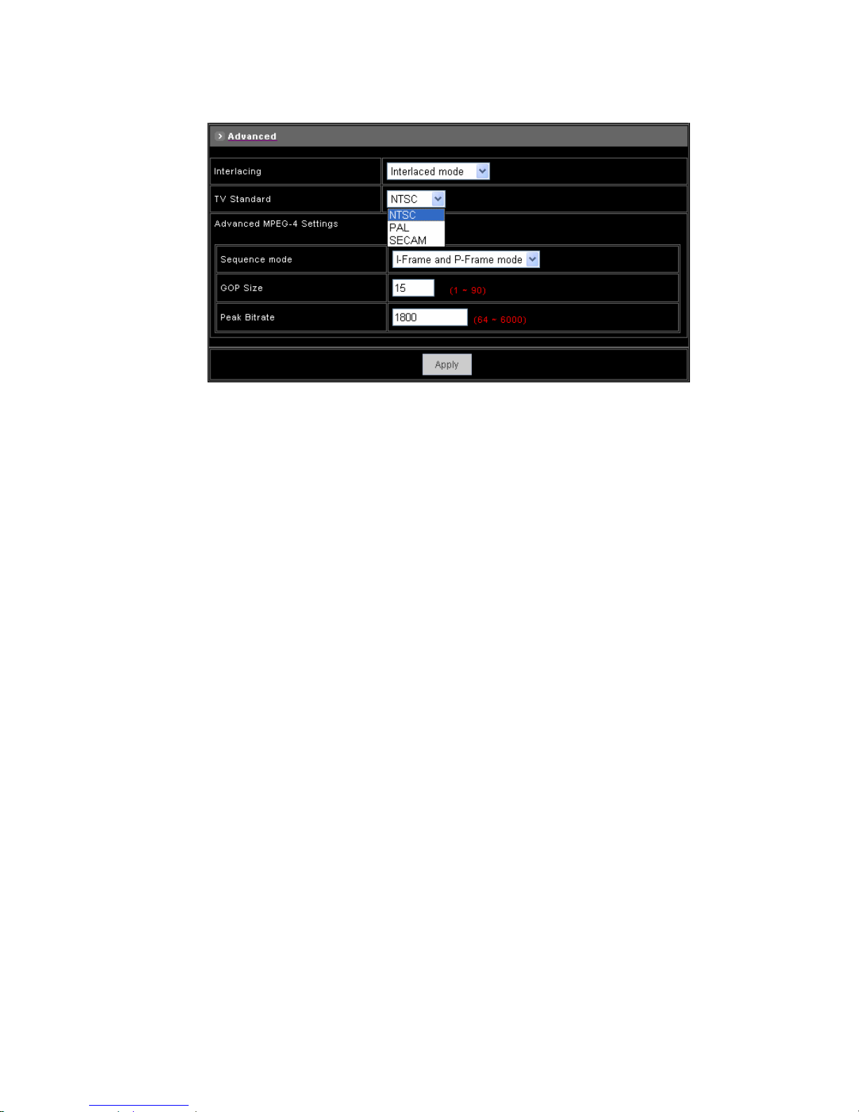
– Advanced A/V Settings
z Interlacing
There are 2 modes available: Interlaced or Progressive.
Interlaced mode is a storage mode. An interlaced video stream contains fields rather than frames, with each field
containing half of the lines of a frame.
A progressive video stream consists of only full frames.
Interlaced video streams can bring a lower bitrate but may cause lower quality.
z TV Standard : The TV standard can be set among these 3 formats NTSC, PAL and SECAM.
z Sequence Mode
There are 2 different modes available:
♦ I-frames only
♦ I-frames and P-frames
P-frames, or predictive frames, are predicted based on prior P or I-frames plus some additional data. They have a
much higher compression ratio than I-frames.
I-frame only mode has very little compression resulting in large file sizes.
I-frame and P-frame mode offers relatively good compression with medium file sizes. Although this requires more
work on the host PC to decode the video.
z GOP Size: GOP stands for Group Of Pictures. It defines the number of frames from one I-frame to the next. Since
an I-frame uses very little compression, while P/B frames use much higher compression, a larger GOP size
results in smaller file sizes.
z Peak Bitrate: This is used to set a maximum bitrate that can be achieved. This is useful for setting bitrates
between the values that are available from the Video Encoder bitrate list.
z Apply: Click this button to save the changes made.
- 40 -
Page 42
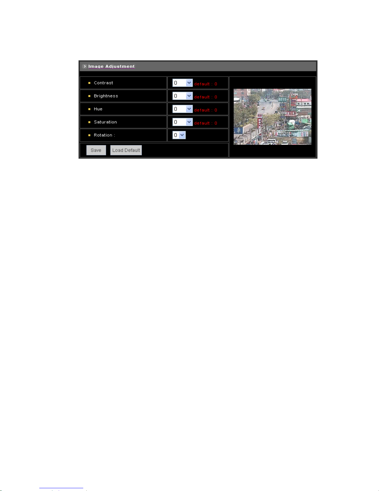
– Image Adjustment
z Contrast, Brightness, Hue and Saturation : The value can be adjusted from -100 to 100.
z Rotation : Rotation degrees run from 0 to 270 degrees for a permanent digital position.
♦ 0: 0 degree
♦ 1: 90 degrees
♦ 2: 180 degrees
♦ 3: 270 degrees
z Load Default : Click this button to set the image adjustments back to factory default.
z Save : Click this button to save the changes made.
- 41 -
Page 43
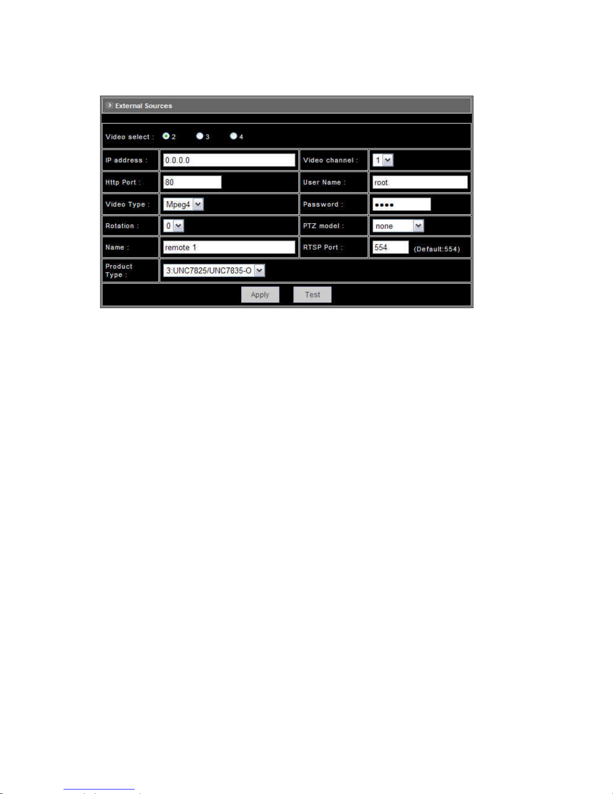
4.3 Setting External Sources
z Video Select : Select the channel this external source will be displayed.
z IP Address : Enter a valid IP address from an IP Camera or Video Server.
z Http Port : Enter the port number used for the IP address for network connection.
z Video Type : Select MJPEG or MPEG4. The type must match the external source provided.
z Rotation : Rotation degrees run from 0 to 270 degrees for a permanent digital position.
♦ 0: 0 degree
♦ 1: 90 degrees
♦ 2: 180 degrees
♦ 3: 270 degrees
z Video Channel : If the external source is a camera connected to a Video Server, select the channel of the Video
Server.
z Username/Password : Enter the respective Username and Password if applicable. If no user has been set for the
device, the default value should be root and pass respectively.
z RTSP Port : Enter a RTSP Port used for streaming in case the external source is a MPEG4 device.
z PTZ Model : Choose a PTZ model.
z Name : Enter a name for the device.
z Product Type : Select from MJPEG or MPEG4 Video Servers or IP Cameras. Please refer to the original
document of the device for a better description.
z Test : Before submitting the information, click on this button to validate the video connection and the live video will
be displayed if the settings are correct.
z Apply : Click on this button to save the changes made.
- 42 -
Page 44
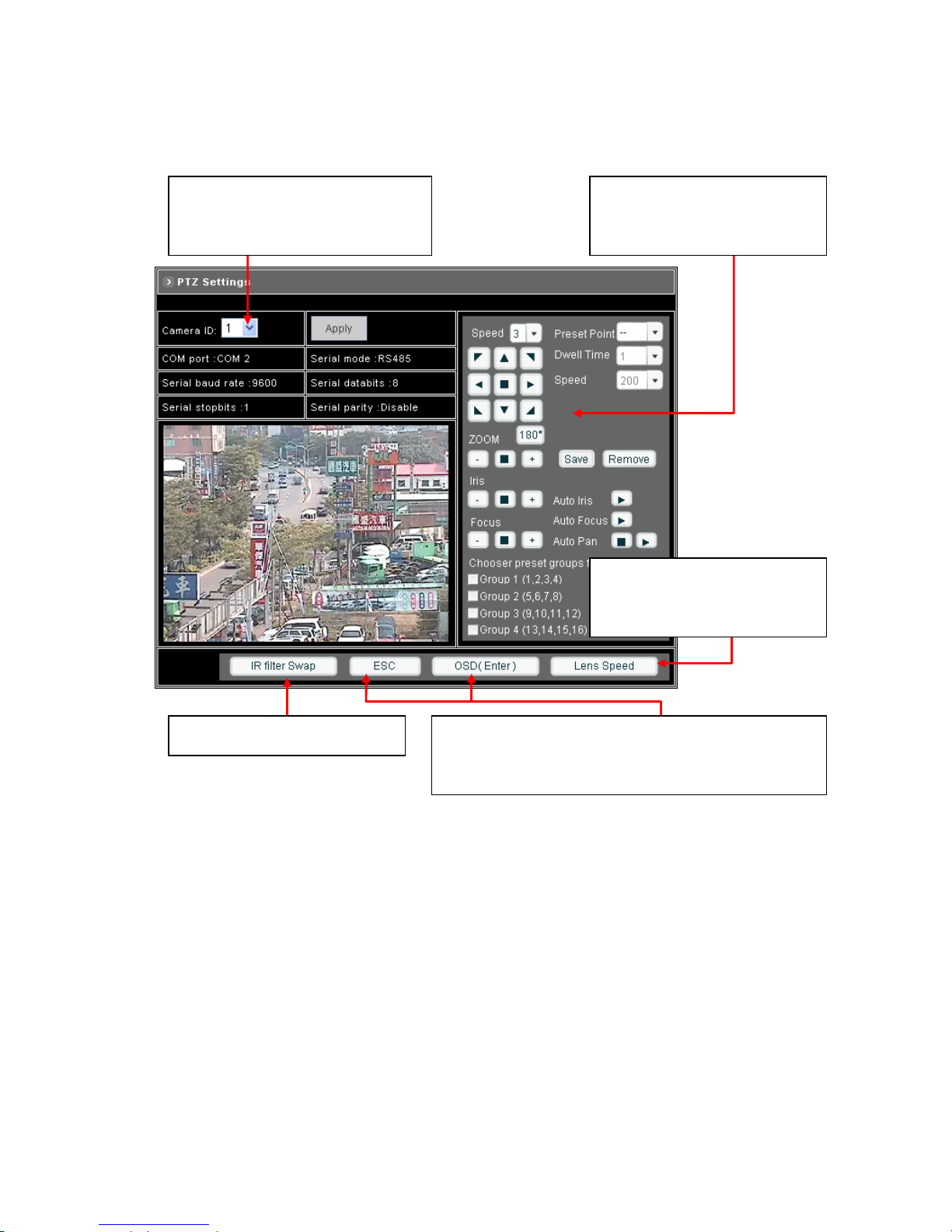
4.4 PTZ Settings
Setting ID for NDC
Select an ID number to match the ID
address set by the dome camera.
Managing Preset Points
Managing the Preset Points for quick
view and auto pan.
Advanced Function Setup for NDC
This pair of buttons is for call out the OSD Setup Menu, and set
up more functions.
Changing Lens Speed
Switching the lens speed between
default setting and manual setting.
Setting Day / Night Mode
– Setting the ID for Network Dome Camera
To select an ID number to match the ID address set by the NDC ID switch:
1. Click on the arrow button beside Camera ID and select the number from the pull-down list.
2. Click on [Apply] button to confirm the selection.
- 43 -
Page 45
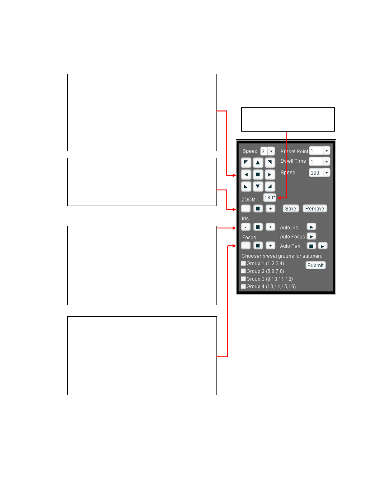
– Operating the Dome Camera
To control the dome camera for viewing, follow the description shown on below:
Pan / Tilt the Dome Camera
To control the pan and tilt movement of the dome camera
simply click on the buttons:
z To pan or tilt, just click on the 8-directions buttons for the
desired direction.
z To adjust the speed of the movement, just click on the
arrow button beside “Speed” and select the desired
speed from the pull-down list. The higher the number
selected, the faster the speed.
Zoom Lens Control
z To zoom in: Click [+] button, the viewing angle becomes
narrower and target will become enlarged on the screen.
z To zoom out: Click [-] button, the viewing angle becomes
wider and target will become smaller on the screen.
Iris Control
The purpose of iris control is to adjust brightness on target. It
can be set as Auto Iris or Manual Iris.
z Iris open: Click [+] button, to open the iris and brighten
the picture.
z Iris close: Click [-] button, to open the iris and reduce
glare.
z Auto iris: Click the arrow button beside “Auto Iris”, the
lens will automatically adjust itself for optimum iris.
Focus Control
The focus function can be set as Auto Focus or Manual
Focus.
z Manual focus near: Click [+] button, the target will
become farther.
z Manual focus far: Click [-] button, the target will become
nearer.
z Auto focus: Click the arrow button beside “Auto Focus”,
the lens will automatically adjust itself for optimum focus.
180o Revolve
The viewing angle will turn 180o.
- 44 -
Page 46
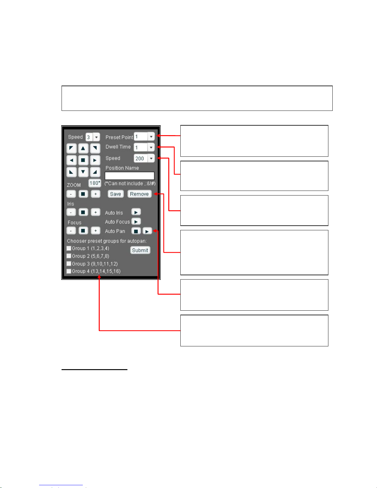
– Preset Point Setting
There are 128 individual preset points. Each preset stores the exact position of the camera and automatic pan, tilt,
zoom, focus and iris setting. Once the data is set, the preset can be recalled for viewing, or the presets can be set for
auto pan.
Setting Preset Point
Note: Only the first 16 preset points of the device can be set to auto pan mode and first 6 preset points are
corresponding with the 6 alarm inputs.
Selecting Preset Point
Click on the arrow button and select the desired number
from the pull-down list.
Setting Preset Dwell Time
Click on the arrow button and select the desired value from
the pull-down list.
Setting Preset Speed
Click on the arrow button and select the desired value from
the pull-down list.
Save / Remove Preset Data
z Click on [Save] button will save the current data as a
preset point.
z Click on [Remove] button will erase all 128 preset points.
Selecting Preset Group for Auto Pan
Select the groups by clicking on the check boxes, then click
[Submit] button to save the changes made.
Activate / Stop Auto Pan
z Activate: Click the arrow button.
z Stop: Click the rectangle button.
1. Select a preset point. (If this point has been set previously, the following procedure will change the previous
settings after saving)
2. Move the camera to the desired view position. (Refer to the previous page)
3. Adjust the zoom, focus and iris of lens. When set up preset point, using manual focus will provide both clarity
and stability of image. (Refer to the previous page)
4. Set preset Dwell time. The dwell time means the time user wants to view on certain preset point under Auto
Pan. The Dwell time can be set between 1 ~ 255 seconds.
- 45 -
Page 47
5. Set preset speed. The speed the dome travels to that preset point can be adjusted between 10 to 250
seconds.
6. The presets Group 1 ~ 4 (First 16 preset points) can be entered a name for identify. Just fill the text string into
the Position Name field.
7. Save the preset point. Once the above steps have been completed, the information must be stored or it will
not be memorized by the system.
Setting Preset Group for Auto Pan
The purpose of setting preset group allows the management of the 16 preset points before Auto Scanning. The
first 16 preset points are separated into 4 groups. Preset group must be set for the auto pan reference.
Note: For the first 16 presets on each dome, the above steps must be repeated. For presets 17 ~ 128 there is
a default speed and dwell setting so steps 4 and 5 are not required.
z Group 1 includes: 1st, 2nd, 3rd and 4th preset points.
z Group 2 includes: 5th, 6th, 7th and 8th preset points.
z Group 3 includes: 9th, 10th, 11th and 12th preset points.
z Group 4 includes: 13th, 14th, 15th and 16th preset points.
To select the groups, click on the check boxes of the groups, then click [Submit] button to save the changes.
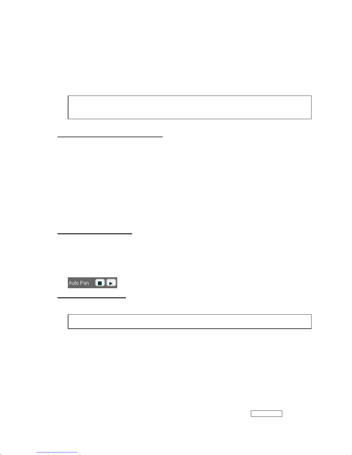
Activate / Stop Auto Pan
When the Auto Pan function is activated, the dome camera will auto touring the preset groups entered.
z To activate: Click the arrow button.
z To stop: Click the rectangle button.
Deleting Preset Points
Sometimes it is necessary to delete the stored preset points. Just click the [Remove] button.
– Setting Day / Night Mode (available for UNC7825(O/OW/OT) )
There are 3 modes can be selected to set the IR Cut Filter for different environment. Click IR filter Swap to switch the
Note: All the preset points can be cleared by clicking on [Remove] button.
- 46 -
Page 48
modes.
z ICR ON (ICR IN): IR Cut Filter is ON and always produce constant color image.
z ICR OFF (ICR OUT): IR Cut Filter is OFF and always produce monochrome image.
z ICR AUTO
♦ UNC7825-O/ UNC7825-OT: When light drops below 3 Lux, switch from color to monochrome automatically.
♦ UNC7825-OW : When light level is over 30 Lux, IR Cut Filter switches IN automatically to produce color
image. When light drops below 10 Lux, IR Cut Filter switches OUT automatically to produce monochrome
image. Under monochrome mode, sensitivity is increased to 0.01 Lux and can be used with IR illuminators.
– Changing the Lens Speed between Default and Manual Setting
Click on Lens Speed to switch the Lens speed between default speed and the manually setup speed.
– Setting More Functions for UNC7825(O/OW/OT)
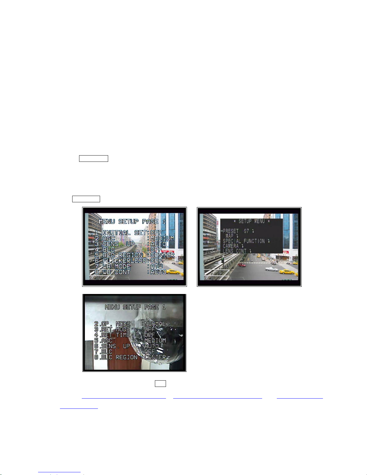
Click OSD(Enter) will call out a SETUP MENU, it allows user to configure more functions for UNC7825 (O/OW).
To close and quit the SETUP MENU, click ESC button.
Refer to “5. Advanced Settings for UNC7825-O”, “6. Advanced Settings for UNC7825-OW” and “7. Advance Settings
for UNC7825-OT”for the details.
- 47 -
Page 49
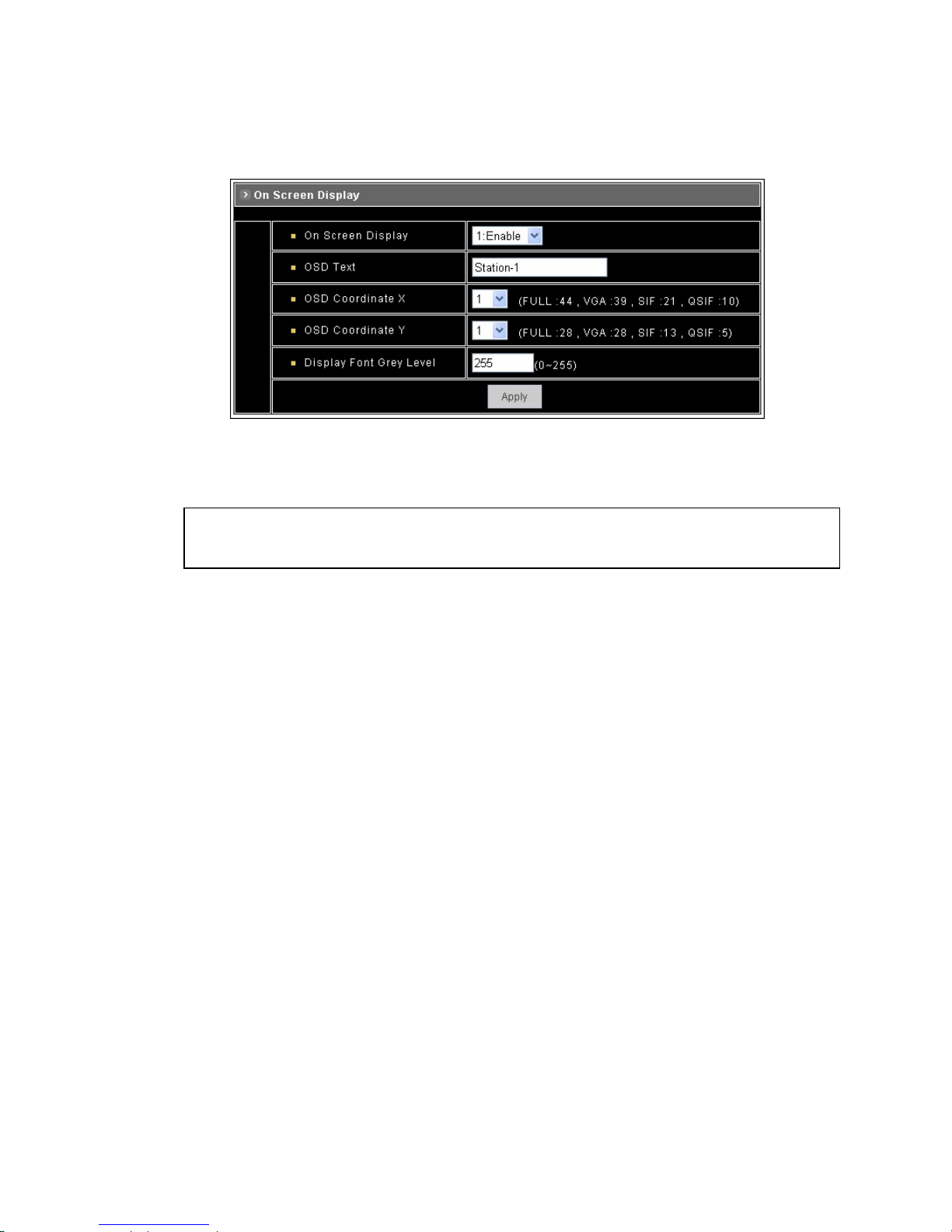
4.5 On Screen Display
z On Screen Display: Select Enable/Disable for displaying the text over the video.
z OSD Text: Fill in the text string to display. The valid characters are a – z, A – Z, 0 – 9, !, @, #, $, %, &, *, ( and ).
Note: The maximum display block area is 12X4 characters. String length longer than 12 will feed to next line,
and total 4 lines are available. More than 4 lines will strip off.
z OSD Coordinate X / Y: To change the location of text, just fill in the X and Y coordinate.
z Display Font Grey Level: Change the color of the displayed font.
z Apply: Click this button to save the changes made.
- 48 -
Page 50
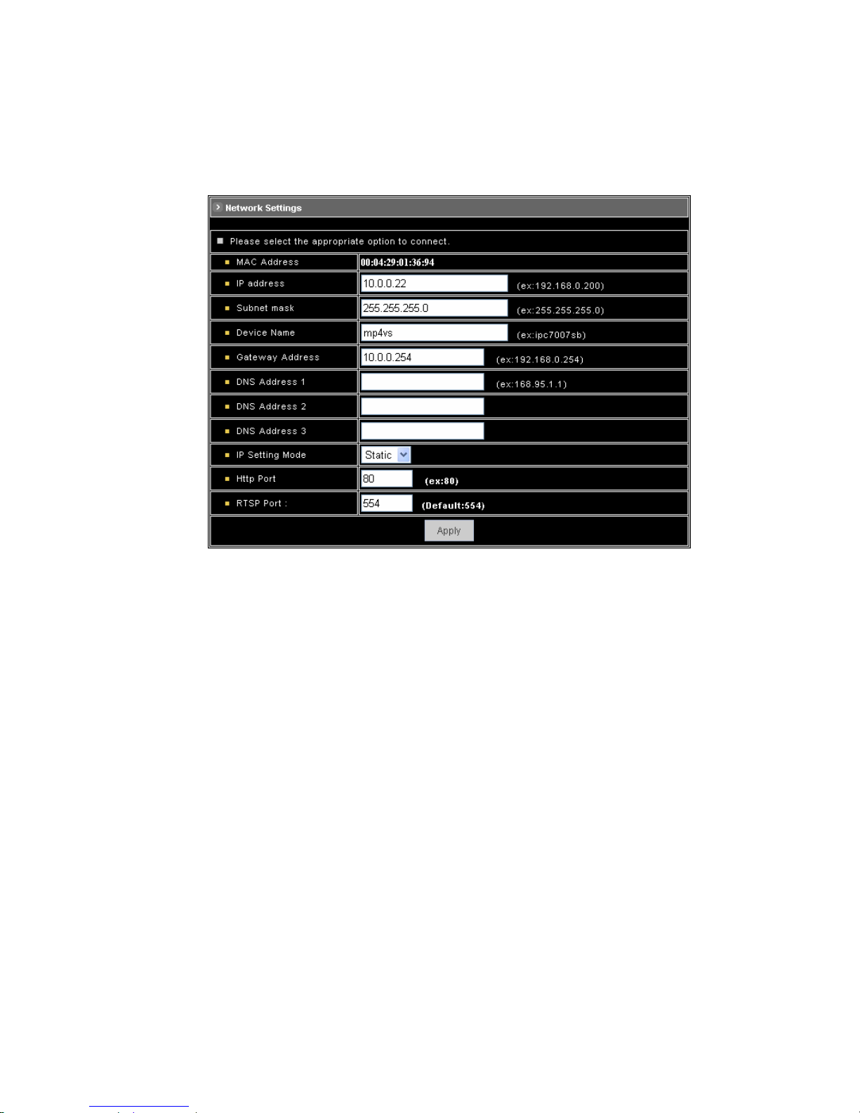
4.6 Configuration of Network Setting
– General Settings
z MAC Address: Display MAC address information for this device. It is read only information.
z IP Address: IP address of the device.
z Subnet Mask: Subnet mask of your LAN. Note that the IP Address above and Gateway IP Address below should
be in the same subnet.
z Device Name: Enter a name for the device.
z Gateway Address: The gateway IP address for the network segment to which the device is connected. This
device traffic to Internet should go through Gateway, if not setting this, only Intranet (LAN) can be accessed.
z DNS Address 1, 2 and 3 : The DNS server IP address used for resolving domain names to IP addresses. DNS
Address 2 and 3 are optional.
z IP Setting Mode
Static IP - Manually assigned IP address.
DHCP – If there is a DHCP server installed on your LAN, you can select DHCP to automatically assign an IP
address for the device and obtain default gateway, and DNS server.
z HTTP Port: Specify the HTTP web server listen port for client (browser) connection. Default uses port 80 (HTTP
standard port), valid range from 0 ~ 65535.
- 49 -
Page 51

Note: Before changing the listen port, user must add a port directive “:” in browser URL in order to get
correct connection. (i.e. http://<IP>:<Port> , e.g. Hhttp://192.168.0.200:8000
H) to access the device
with IP 192.168.0.200 and port with 8000).
These features enable user to use the device behind NAT or IP Sharing devices which could access
up to 65536 NDC with one IP Address.
z RTSP Port: The port on which the device will receive RTSP (streaming video) requests.
z Apply: Click this button to save the changes made.
– Dynamic DNS Settings
The DDNS (Dynamic Domain Name Service) is used when users want to access the NDC with an easy memorized
name such as http://demo.server.ddns.com instead of http://61.220.235.172. This service could be useful when the
NDC is located behind Dial-up ADSL or IP sharing devices, which does not have fix IP address, then it’s impossible to
reach the NDC from Internet.
When the NDC enables the DDNS service, it will “register” to the DDNS server with its information, such as server
name to access, router virtual port number and updated frequency, etc.
Then NDC automatically “update” to the DDNS server by a fix frequency, so even the IP is changed by ISP, the DDNS
server still could get and update internal database. Then, once users access from Internet with its register name, e.g. if
registering with server name “demo” to DDNS server “server.ddns.com”, the NDC could be accessed by
http://demo.server.ddns.com.
- 50 -
Page 52
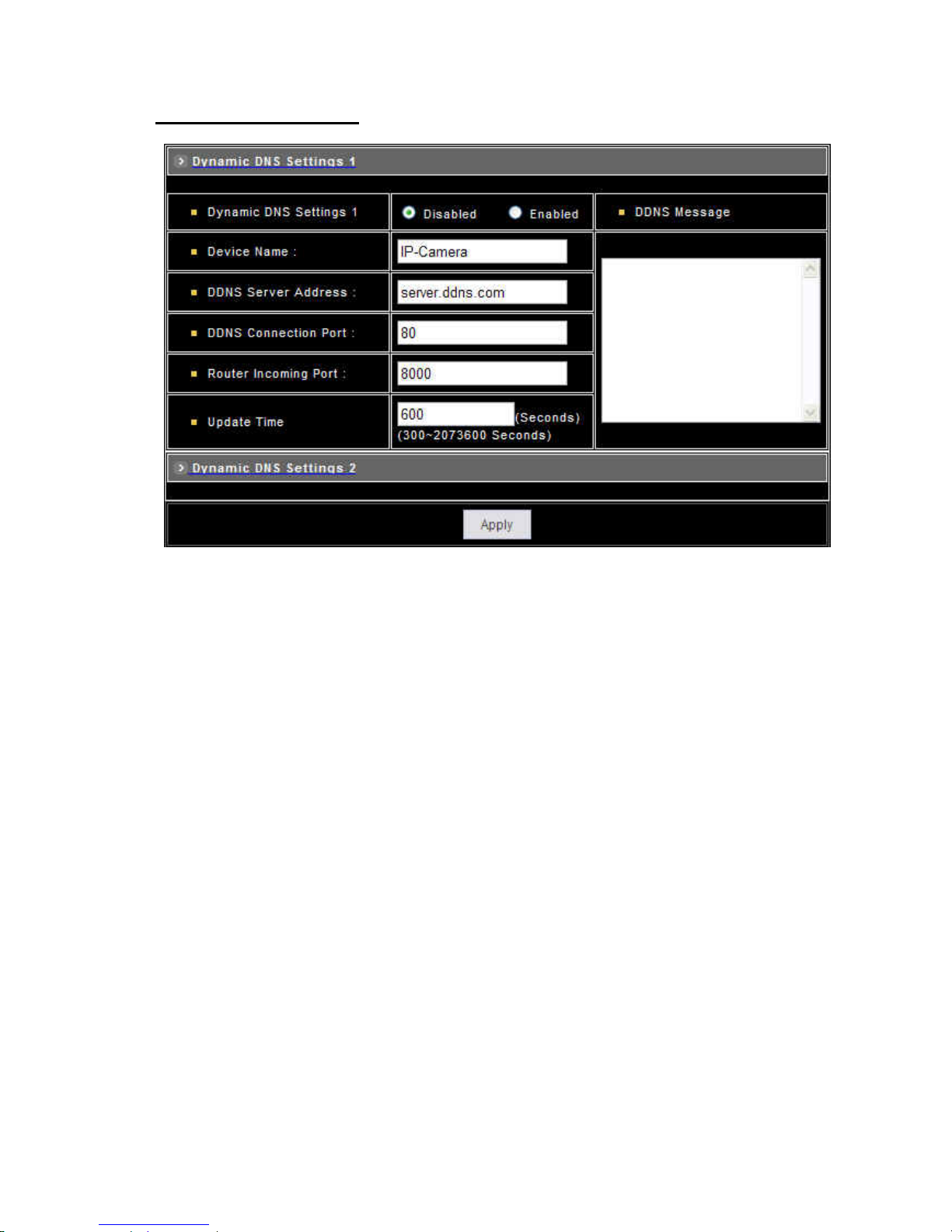
Dynamic DNS Settings 1
z Dynamic DNS Settings: Select [Enable] if you wish to activate the DDNS service.
z Device Name: Specify server name. This name setting also used by the DDNS service to recognize each server.
E.g. if configure name as “user” to DDNS address “server.ddns.com”, then this NDC can be accessed by URL
http://user.server.ddns.com after register to the DDNS server.
z DDNS Server Address: Specify address of the DDNS server.
z DDNS Connection Port : Specify the DDNS server listen port, and the default is “80”
z Router Incoming Port: Specify your router listen port for the DDNS server to redirect. The router may configure the
different port for incoming (Internet request) and outgoing (Intranet request), e.g. it may configure to redirect
Internet HTTP (port 80) request to Intranet port 8000, then, in this case, we must configure the “Router Incoming
Port” to 80, and inside the NDC Network settings should set HTTP port with 8000.
z Update Time: Specify the NDC updated frequency in seconds, and the default is 600 (10 minutes), this is interval
that NDC will automatically send an updated packet to the DDNS server.
z DDNS Message: Return messages from remote DDNS server, and some hints may help to diagnostic the reason
if register fails.
♦ DDNS addr. CGI fail:
It means that NDC can’t communicate with Internet world. Make sure your Network Configuration has correct
subnet mask and default gateway, and DNS1 setting is correct and reachable.
♦ Already registered:
Another user had registered this name; please change your register name by changing “Device Name”.
z Apply: Click this button to save the changes made.
- 51 -
Page 53
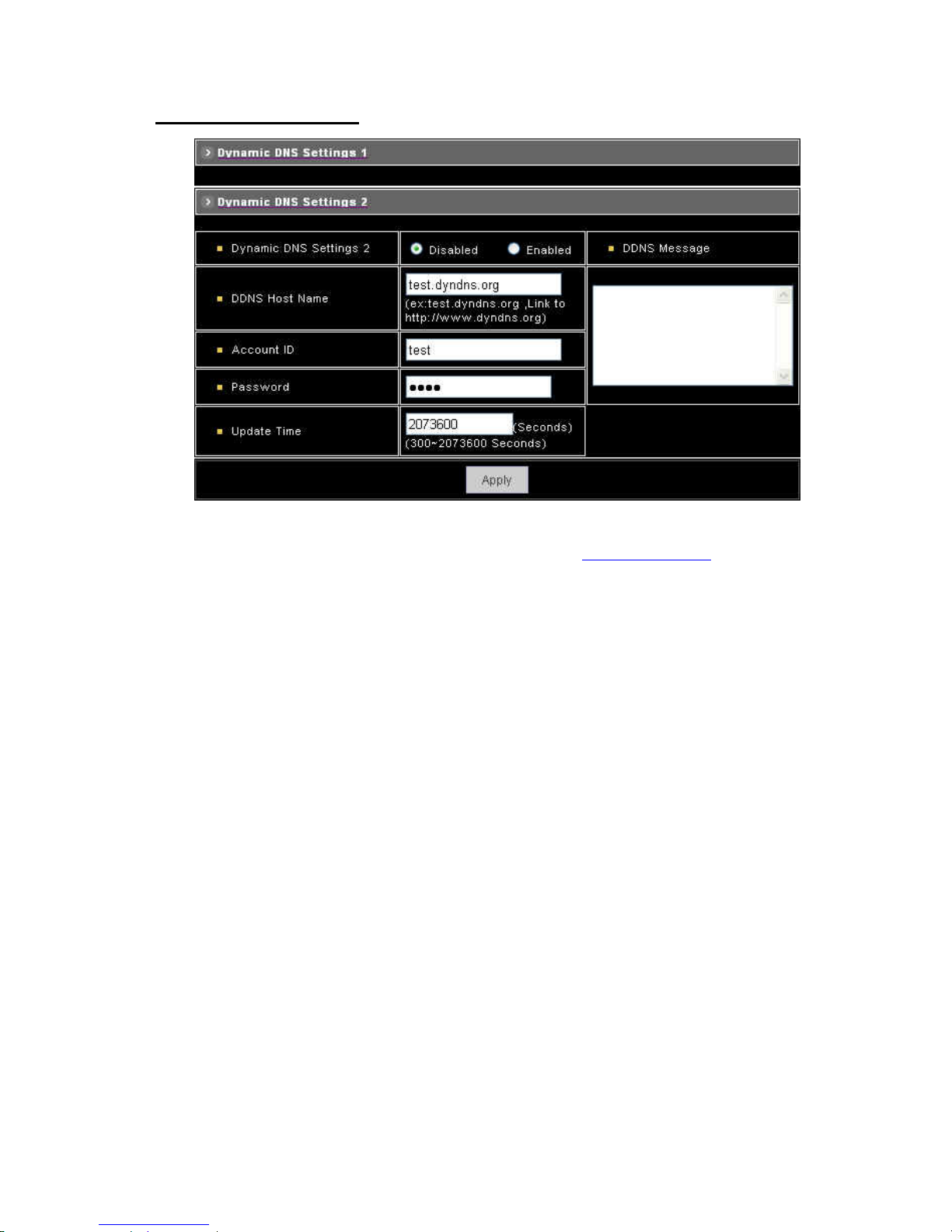
Dynamic DNS Settings 2
z Dynamic DNS Settings : Select [Enable] if you wish to activate the DDNS service through DynDns.
z DDNS Host Name : Specify server name that you have registered in
http://www.dyndns.org
E.g. if the registered name is “user” to DynDns, then this NDC can be accessed by URL http://user.dyndns.org
z Account ID : Enter the username provided by DynDns.
z Password : Enter the respective password for the account.
z DDNS Message : Return messages from remote DynDns server.
z Apply : Click this button to save the changes made.
Example:
To setup a NDC (IP address 192.168.0.200) behind a dialup ADSL router, and wish to access by name
http://demo.ddns.com. And, the procedure is as below:
Configure the ADSL router with PPPoE enable; LAN IP, 192.168.0.254; and subnet mask, 255.255.255.0.
1. Assign the ADSL router’s virtual server with service port 80 to server IP 192.168.0.200
2. In Network Settings > General page, configure the NDC network configuration with IP address 192.168.0.200;
subnet 255.255.255.0; DNS1 with valid DNS address such as 168.95.192.1 or 168.95.1.1; gateway IP address
with 192.168.0.254 (router’s IP); HTTP port with port 80.
3. Configure the Device Name.
4. Configure Dynamic DNS Settings with Enabled; DDNS Server Address with “ddns.com”; DDNS Connection Port
with port 80; Router Incoming Port with 80; and Update Time with 600 (10 minutes). Finally, clicks [Apply] button.
5. If DDNS message success, then enter URL http://demo.ddns.com on browser. Consequentially, it will show the
NDC’s home page.
- 52 -
Page 54
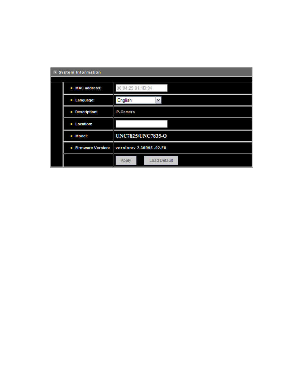
4.7 Configuration of System
– System Information
z MAC Address : Display MAC address information for this device. It’s read only.
z Language : Alternative language option. User may change the language of web contents for different application.
z Description : Useful as an administrative identifier. Does not affect the operation of the device.
z Location : Useful for identifying the position of the device. Does not affect the operation of the device.
z Model : Displays the model number for the device.
z Firmware Version : Display firmware version information.
z Load Default : Click this button to restore the settings back to factory default.
z Apply : Click this button to save the changes made.
- 53 -
Page 55
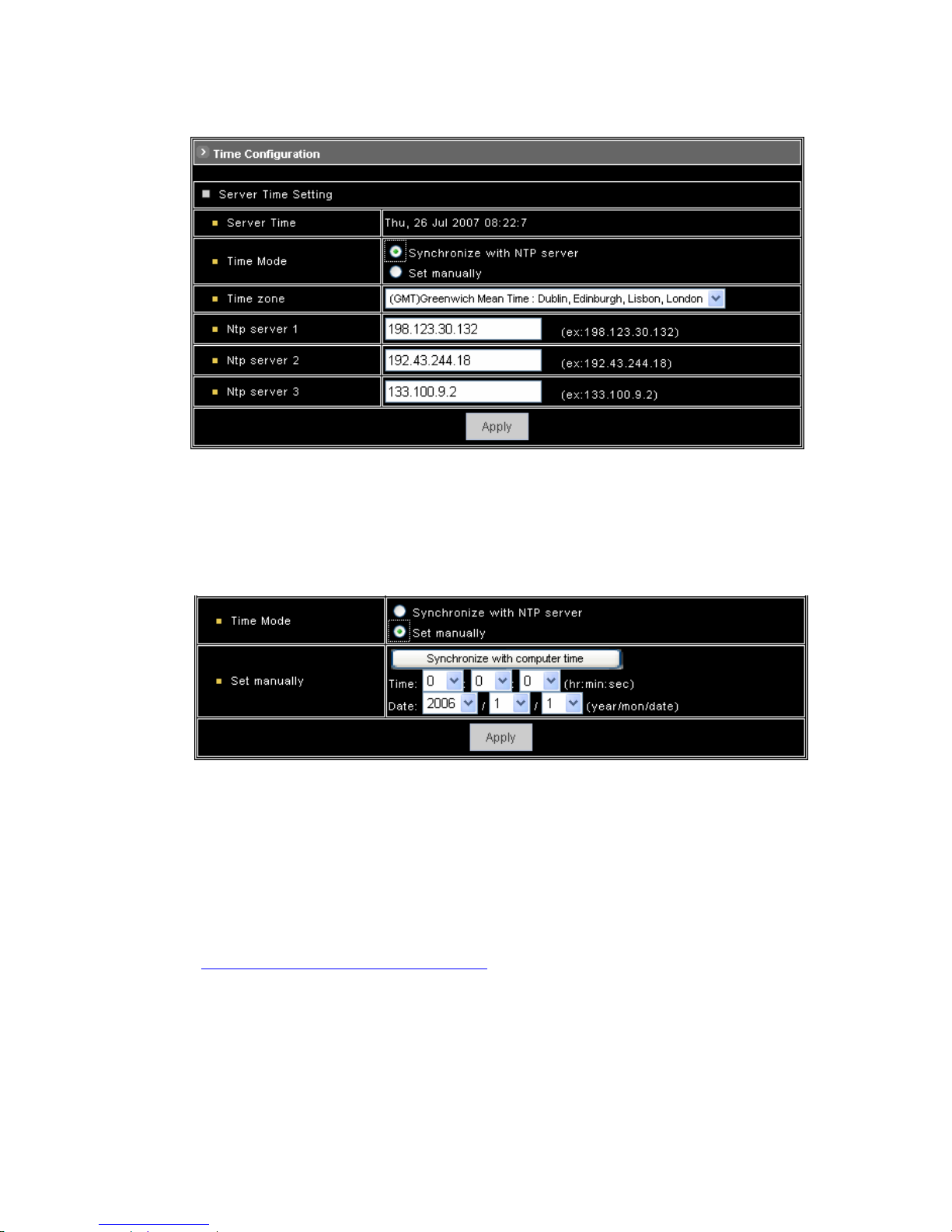
– Time Configuration
z Time Mode
♦ Synchronize with NTP server: Synchronize the current time with a NTP server over Internet.
♦ Set Manually: Manually set the time.
Click on [Synchronize with computer time] button to set the date/time of the NDC as your PC’s, or
Set the date and time by clicking on the arrow button beside each field and select the value from the
pull-down list.
Click on [Apply] button to save the configuration.
z Time Zone: Click on the arrow button and select the appropriate time zone from the pull-down list.
z NTP Server 1, 2 and 3: Assign the NTP servers to use for time synchronization. A list of NTP servers can be found
at:
http://www.eecis.udel.edu/~mills/ntp/clock2a.html
z Apply: Click this button to save the changes made.
- 54 -
Page 56
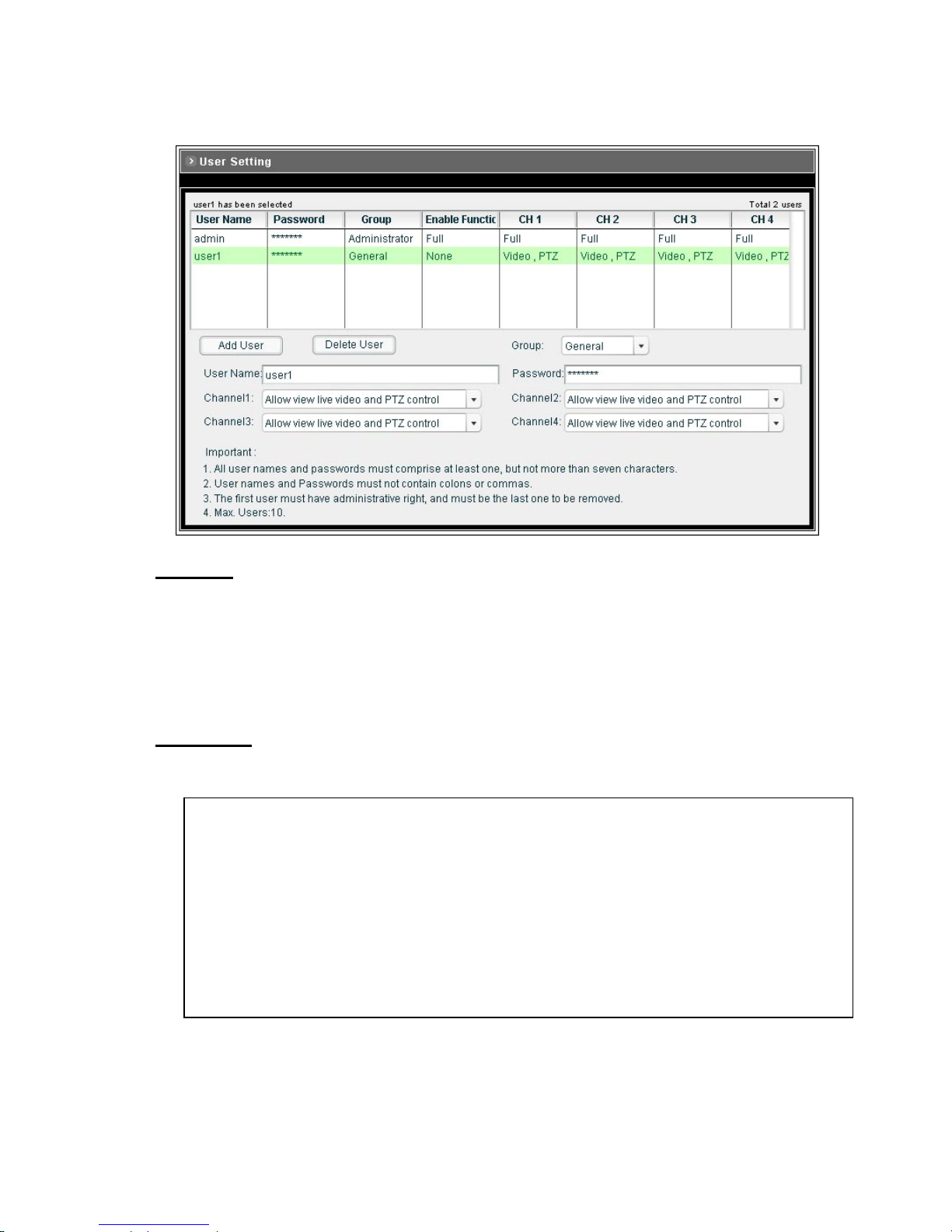
– User Settings
Add User
To add a user, enter the user name and password in the respective fields. Select the [Group] and the [Permission]
of each channel, and then click on [Add User] button.
z The user in Administrator group has all permission to operate the device.
z The user in General group can be configured to have limited permission to operate the device.
Delete User
To remove a user, select the user from the list, and then click on [Delete User] button.
Note:
z Totally 10 users can be added.
z The first added user must have administrative right (Administrator group), and must be the last one to be
removed.
z The username and password cannot contain the “:”, “,” characters. And the length must be between 1 and
7 characters.
z User name cannot be modified
- 55 -
Page 57
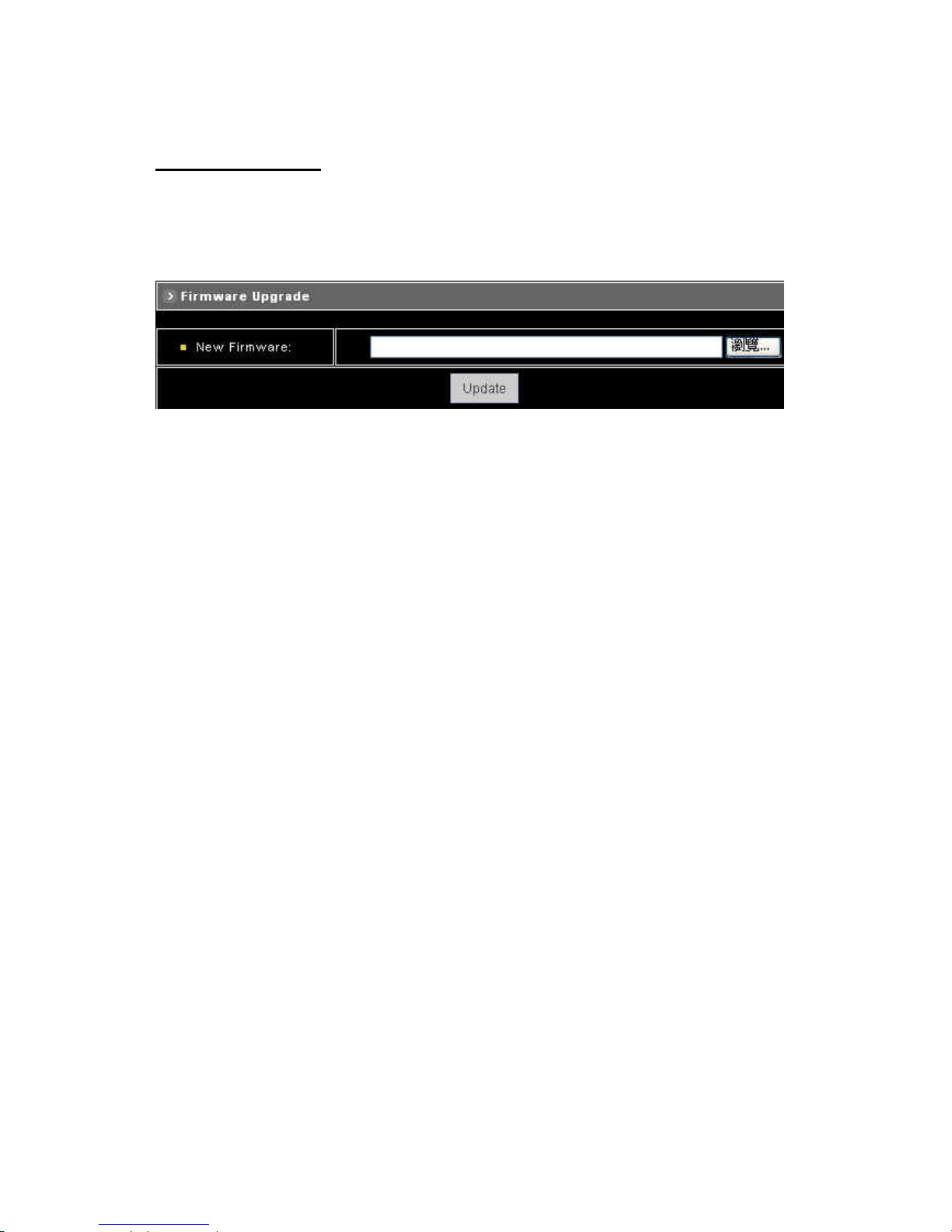
- Firmware Upgrade
Upgrading firmware
To upgrade firmware, first browse the folder where you have placed the newest firmware. After finding the path then
click on “Update” to upgrade the device.
- 56 -
Page 58
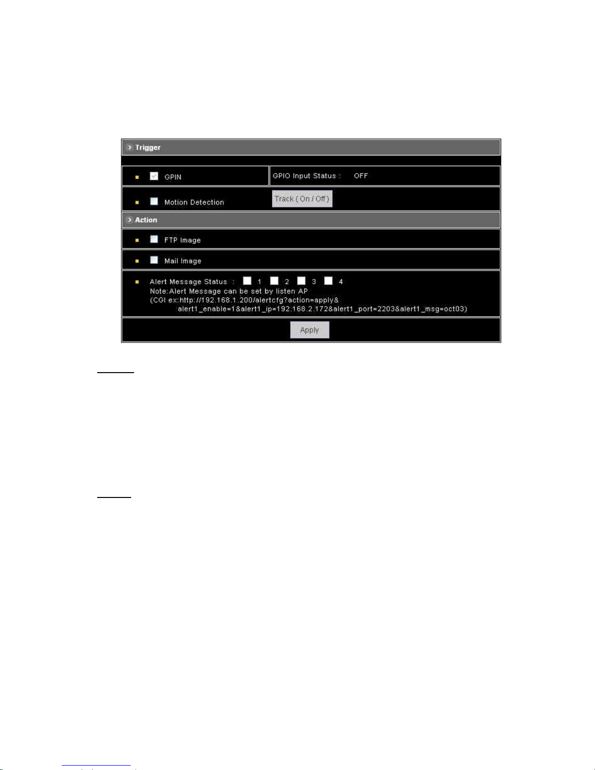
4.8 Configuration of Event
– General
Trigger
System provides “GPIN” and “Motion Detection” for event detection.
z GPIN & GPIO Input Status : They are auto detected and display the status.
z Motion Detection : Make a checkmark on this option to start detect the motion area. See next segment to set the
motion area.
z Track (On/ Off) : Turning on or off the tracking function
Action
Make a checkmark on either FTP Image, Mail Image, or on all of them, to determine what action should be taken
when the event is triggered.
z FTP Image : Send the image to the configured FTP site when event is triggered. Click on the link to set the FTP
server.
z Mail Image: Send the image to the configured mail address when event is triggered. Click on the link to set the
Email addresses.
z Alert Message Status : They are auto detected to display the status, the signal can be used with the recording
application software on PC.
Apply : Click this button to save the changes made.
- 57 -
Page 59
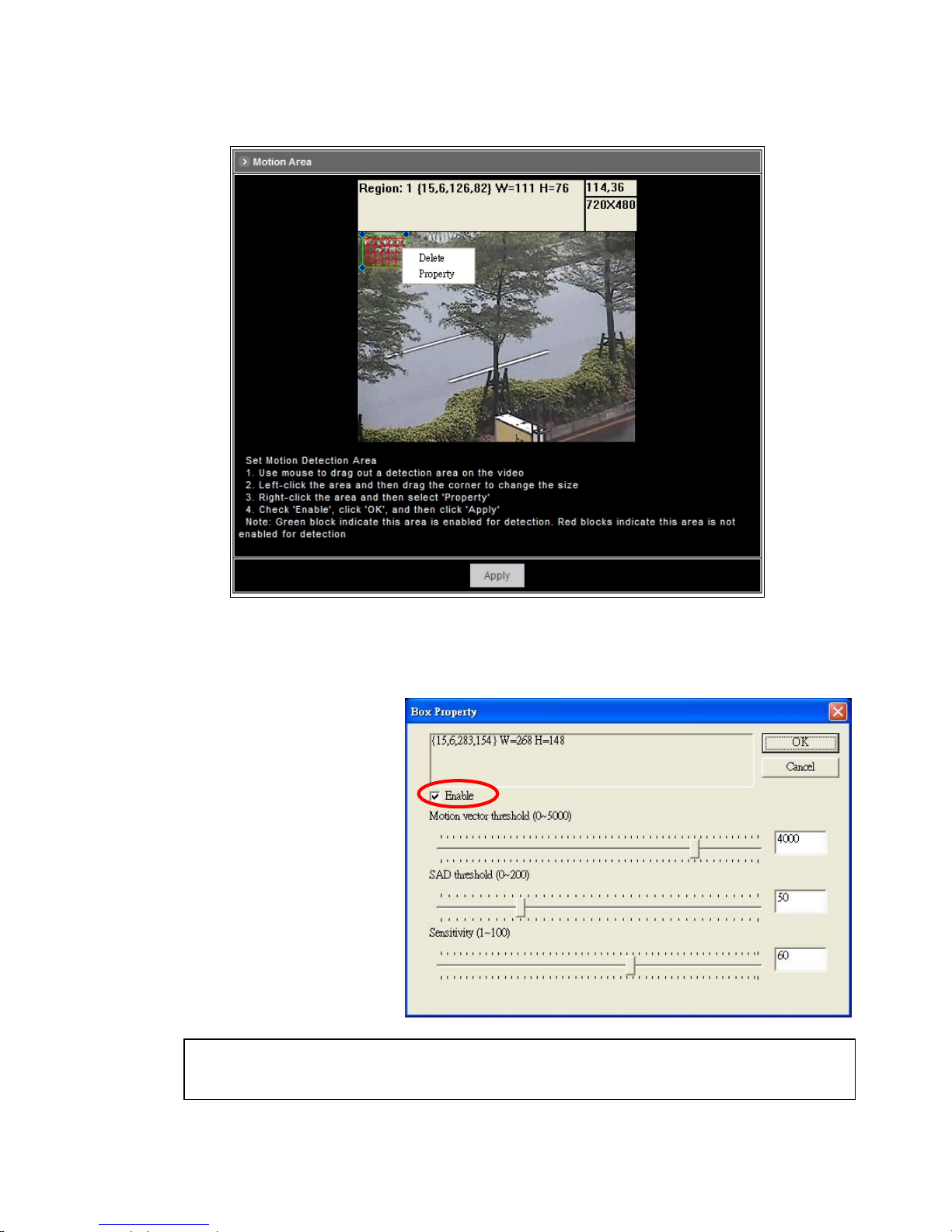
– Set Motion Area
The “Motion Detection” checkbox (Configuration>Event>General>Trigger) must be enabled when use this function.
1. Use mouse to drag out a detection area on the video.
2. Left-click the area and drag the c
Right-click the area and selec
orner to change the size.
3. t
4. e”, click “OK” and click
“Property”.
Check “Enabl
“Apply”.
Note: Green blocks indicate this area is enabled for detection. Red blocks indicate this area is not enabled for
detection.
- 58 -
Page 60
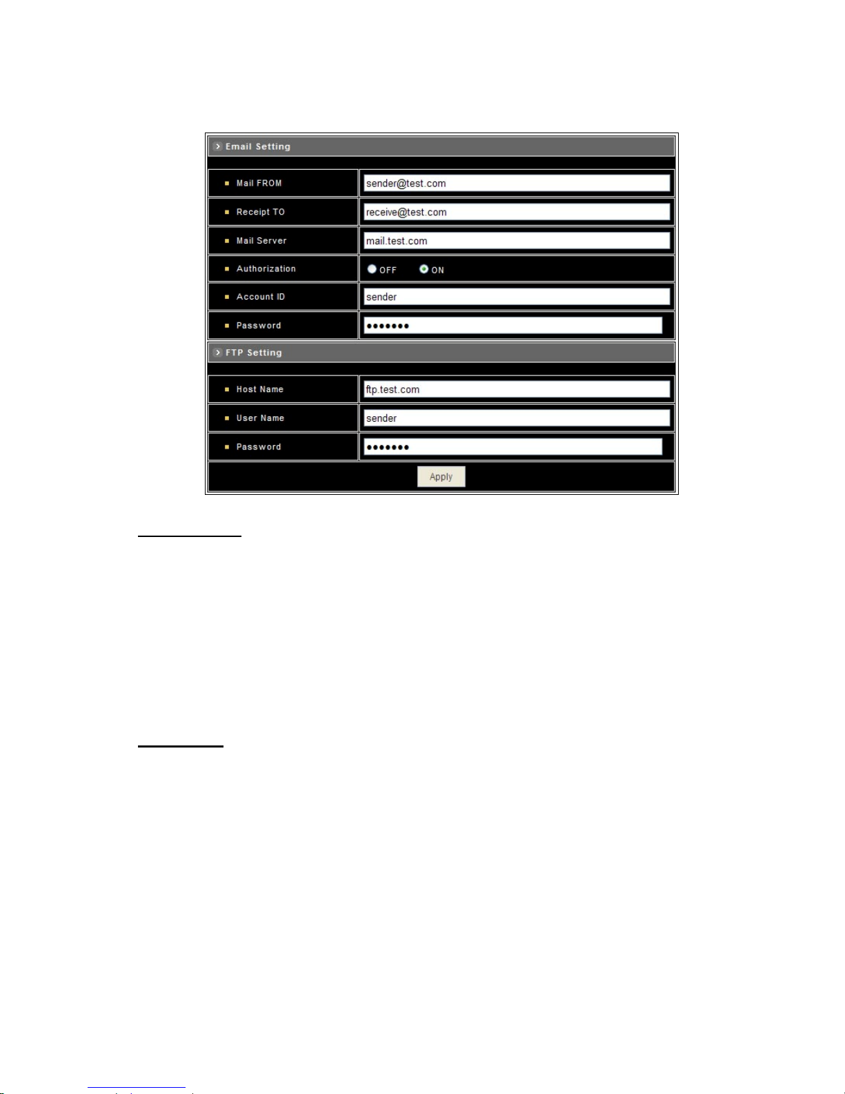
– Set Email and FTP
E-mail Setting
The “Mail Image” checkbox (Configuration>Event>General>Action) must be enabled when use this function.
z Mail From : Enter the mail address of the mail sender.
z Receipt To : Enter the mail address of the mail receiver.
z Mail Server : Enter the mail server name or IP address.
z Authorization : Disable or enable the security for mail authorization.
z Account ID and Password : Enter the user name and password for the mail sender.
FTP Setting
The “FTP Image” checkbox (Configuration>Event>General>Action) must be enabled when use this function.
z Host Name : Enter the IP address of the FTP server.
z User Name and Password : Enter the user name and password for the FTP server.
Apply : Click this button to save the changes made.
- 59 -
Page 61
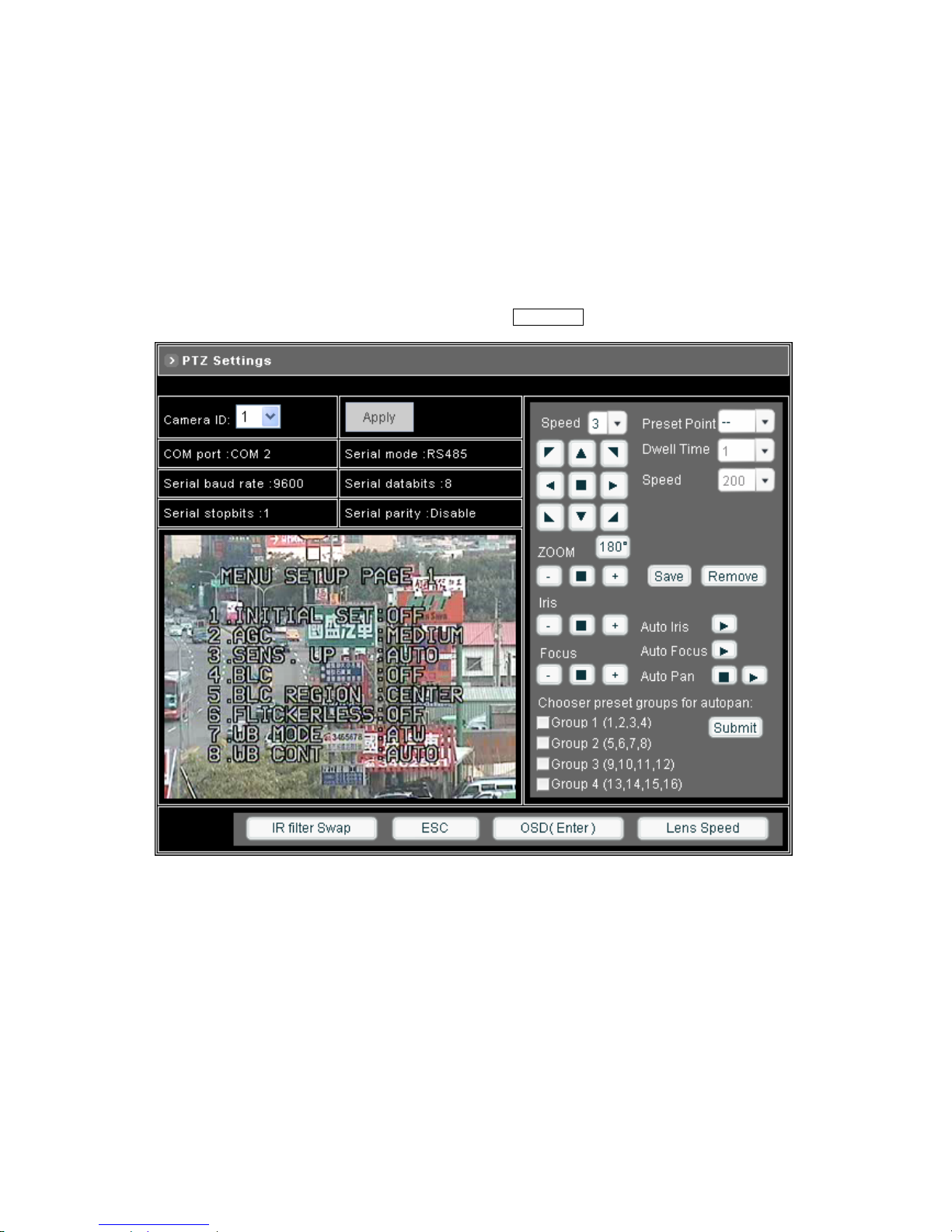
5 Advanced Settings for UNC7825-O
You can use the Web-based user interface to configure the most of functions for the UNC7825-O. Some advanced
functions can be set via an on-screen display (OSD) setup menu.
5.1 Call Out the OSD Setup Menu
In Configuration > A/V Settings > PTZ Settings page, click on OSD(Enter) to call out the SETUP MENU.
Functions List
1. Factory Default Setting
2. Auto Gain Control Selection
3. Sensitivity Enhancement ON/OFF
4. Back Light Compensation ON/OFF
5. Back Light Compensation Zone Selection
6. Flickerless ON/OFF
7. White Balance Mode Selection
8. White Balance Condition Display
9. GAMMA (Brightness) Adjustment
- 60 -
Page 62
10. Pedestal Adjustment
11. Horizontal & Vertical Aperture Correction Slice Level Adjustment
12. Vertical Aperture Correction Slice Level Adjustment
13. Horizontal Aperture Correction (Low Band) Gain Level Adjustment
14. Horizontal Aperture Correction (High Band) Gain Level Adjustment
15. Vertical Aperture Correction Gain Control Adjustment
16. Horizontal & Vertical Aperture Correction Gain Adjustment
17. Manual Iris Speed Selection (Refer to Page33)
18. Manual Zoom Speed Selection (Refer to Page 29)
19. Manual Focus Speed Selection (Refer to Page 32)
20. Auto Focus Mode Selection (Refer to Page 31)
21. IR Cut Switch
Setup Menu Item Selection
1. Click the Down button to select next item.
2. Click the Up button to select previous item.
3. Click the Left or Right button to make selection.
To Exit Setup Menu
Click ESC button, "Setup Initialize..." message will be displayed on the monitor for 4~5 seconds. All setting is stored in
the NDC.
5.2 Set Up Functions
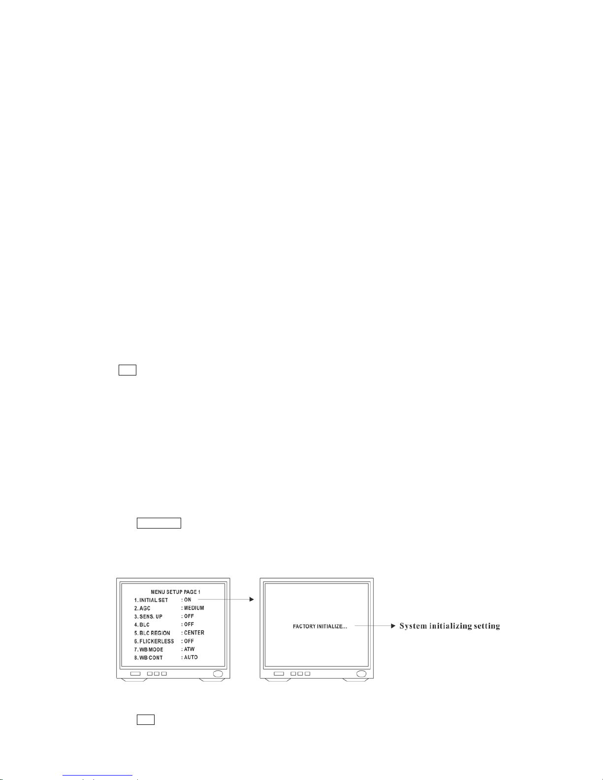
Initial Setting (Factory Default)
To reset all functions back to initial factory setting:
1. Click OSD(Enter) to recall OSD Setup Menu.
2. Click the Up or Down button to select 1st item "Initial Set" on menu and click Left or Right button to make
selection. Once ON is selected, "Factory Initialize..." message will be displayed on screen for 4-5 seconds.
3. When "Initialize" is done, monitor screen will switch back to Setup Menu.
4. Click ESC button to exit menu, when finish or click Up or Down button to select next item.
- 61 -
Page 63
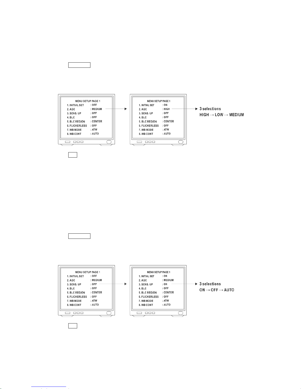
Auto Gain Control Selection
There are 3 different AGC levels can be selected. (Low = 8dB ; Medium = 22dB ; High = 36dB). Different AGC levels
may make different camera performance under low light environment. (Factory Default AGC is Medium)
1. Click OSD(Enter) to recall OSD Setup Menu.
2. Click the Up or Down button to select 2nd item "AGC" on menu.
3. Click Left or Right button to make selection : High -> Low -> Medium
4. Click ESC button to exit menu, when finish or click Up or Down button to select next item.
Sensitivity Up (Enhancement)
Sensitivity Up function allows user to select different Video Gain (Y Gain) control. (Factor Default is AUTO)
z AUTO : System auto turn on or off Video Gain Control function according to target's brightness.
z ON : Video Gain Control Enhancement always on.
z OFF : Video Gain Control Enhancement always off.
1. Click OSD(Enter) to recall OSD Setup Menu.
2. Click the Up or Down button to select 3rd item "SENS UP" on menu.
3. Click Left or Right button to make selection : Auto -> On -> Off
4. Click ESC button to exit menu, when finish or click Up or Down button to select next item.
- 62 -
Page 64
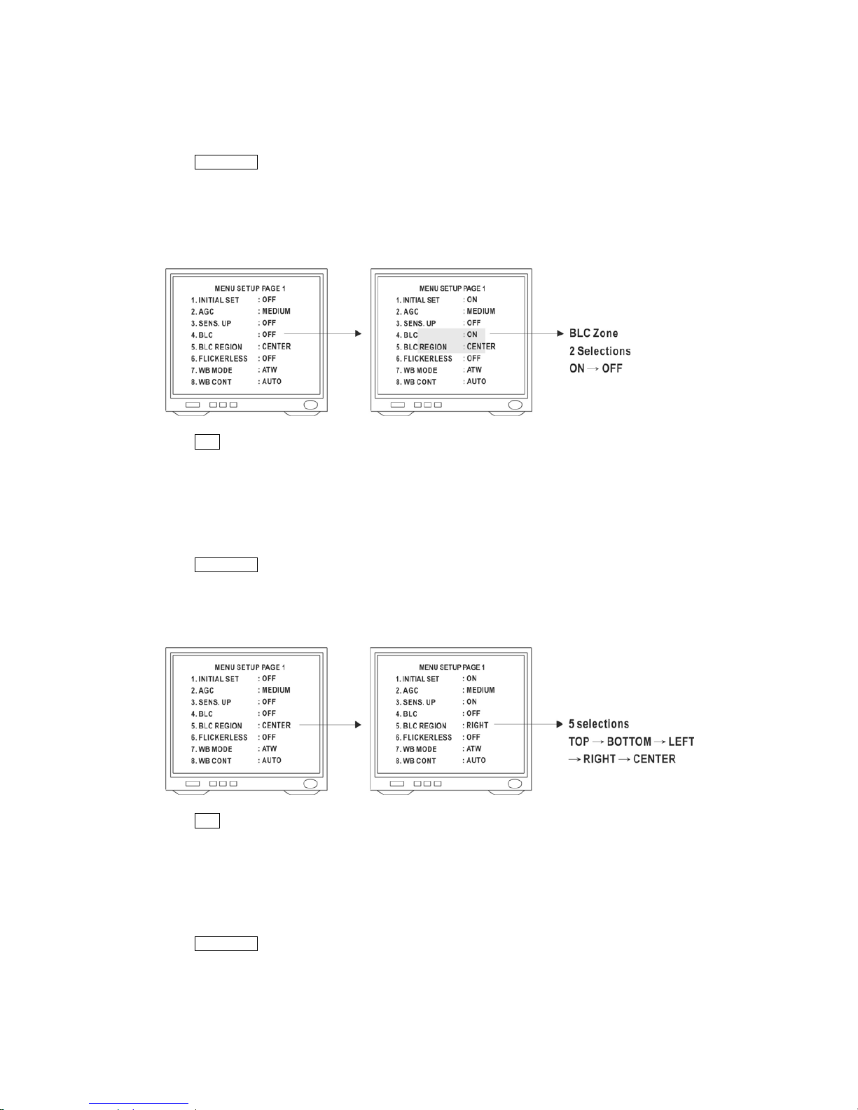
Back Light Compensation
Back Light Compensation can be turned on or off. (Factory Default is OFF)
1. Click OSD(Enter) to recall OSD Setup Menu.
2. Click the Up or Down button to select 4th item "BLC" on menu.
3. Click Left or Right button to make selection : On -> Off
Note : When "ON" is selected, BLC zone will be showed on monitor screen.
4. Click ESC button to exit menu, when finish or click Up or Down button to select next item.
Back Light Compensation Zone Selection
One of five different zone can be selected for BLC. (Factory Default is Center)
1. Click OSD(Enter) to recall OSD Setup Menu.
2. Click the Up or Down button to select 5th item "BLC Region" on menu.
3. Click Left or Right button to make selection : Top -> Bottom -> Left -> Right -> Center
4. Click ESC button to exit menu, when finish or click Up or Down button to select next item.
Flickerless
Flickerless function can be turned on or off. (Factory Default is OFF)
1. Click OSD(Enter) to recall OSD Setup Menu.
2. Click the Up or Down button to select 6th item "Flickerless" on menu.
3. Click Left or Right button to make selection : On -> Off
Note : When "ON" is selected, Shutter Speed will be fixed at 1/100 sec in NTSC or fixed at 1/120 sec in PAL.
- 63 -
Page 65
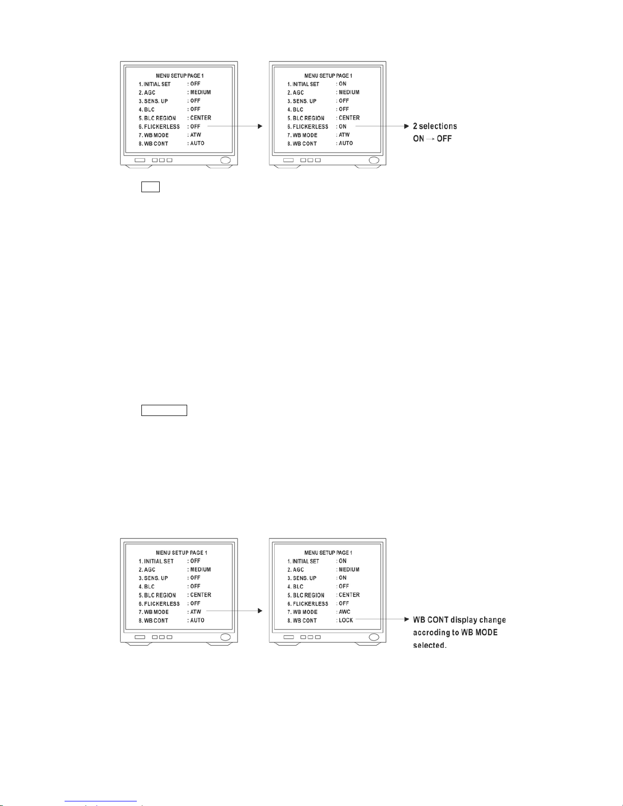
4. Click ESC button to exit menu, when finish or click Up or Down button to select next item.
White Balance Mode Selection
One of four different White Balance Modes can be selected. (Factory Default is ATW)
z ATW : Auto Trace White Balance, is a feedback system that automatically aligns the white balance by detecting the
R-G and B-G before gamma correction processing.
z AWC : Auto White Balance Correction, is performed at a faster operating speed than ATW without an operation or
other limitations.
z Indoor : Fix mode White Balance, suitable for 3200K color temperature environment.
z Outdoor : Fix mode White Balance, suitable for 6400K color temperature environment.
1. Click OSD(Enter) to recall OSD Setup Menu.
2. Click the Up or Down button to select 7th item "WB Mode" on menu.
3. Click Left or Right button to make selection : AWC -> Indoor -> Outdoor -> ATW
Note : When AWC is selected, "Lock" will be showed under "WB Cont".
When Indoor is selected, "3200K" will be showed under "WB Cont".
When Outdoor is selected, "6400K" will be showed under "WB Cont".
When ATW is selected, "Auto" will be showed under "WB Cont".
- 64 -
Page 66
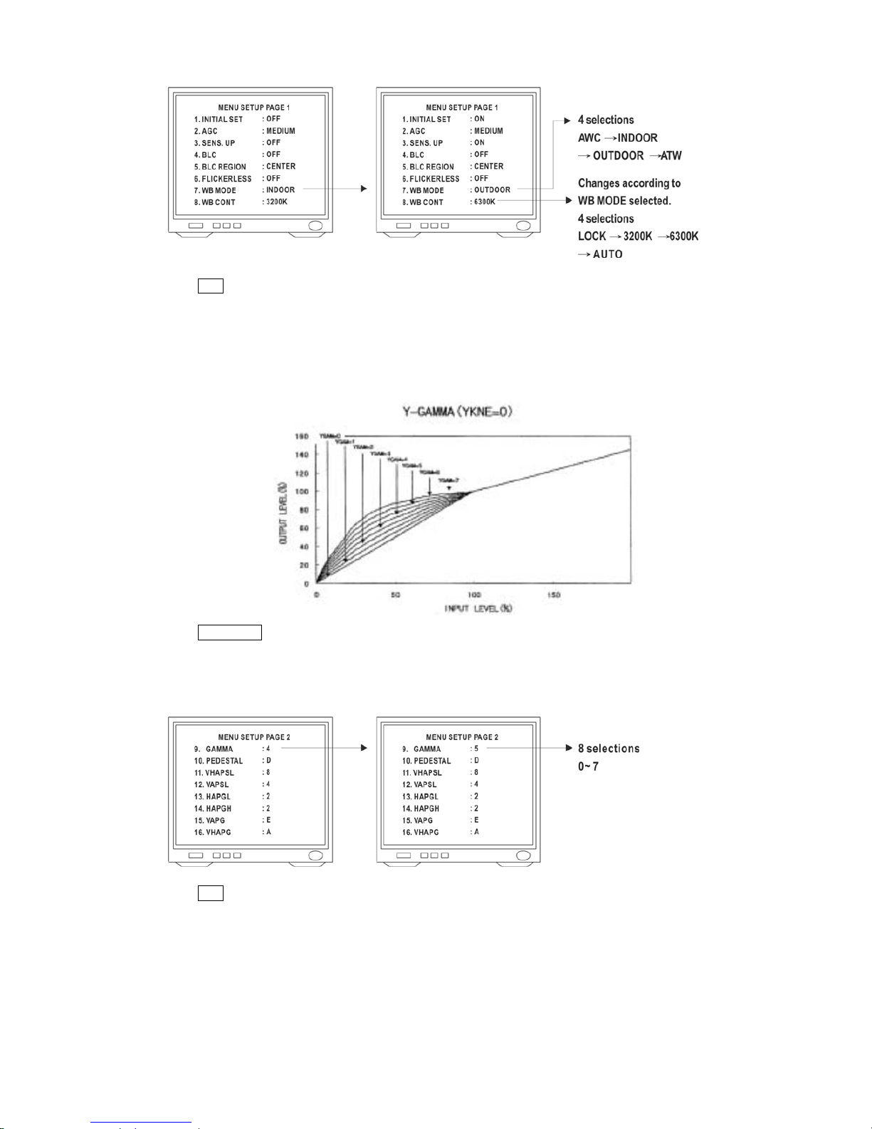
4. Click ESC button to exit menu, when finish or click Up or Down button to select next item.
Gamma Adjustment (Brightness)
8 levels of Gamma (Brightness) can be adjusted. (Factory Default is 4)
1. Click OSD(Enter) to recall OSD Setup Menu.
2. Click the Up or Down button to select 9th item "Gamma" on menu.
3. Click Left or Right button to make selection : 0 ~ 7
4. Click ESC button to exit menu, when finish or click Up or Down button to select next item.
- 65 -
Page 67
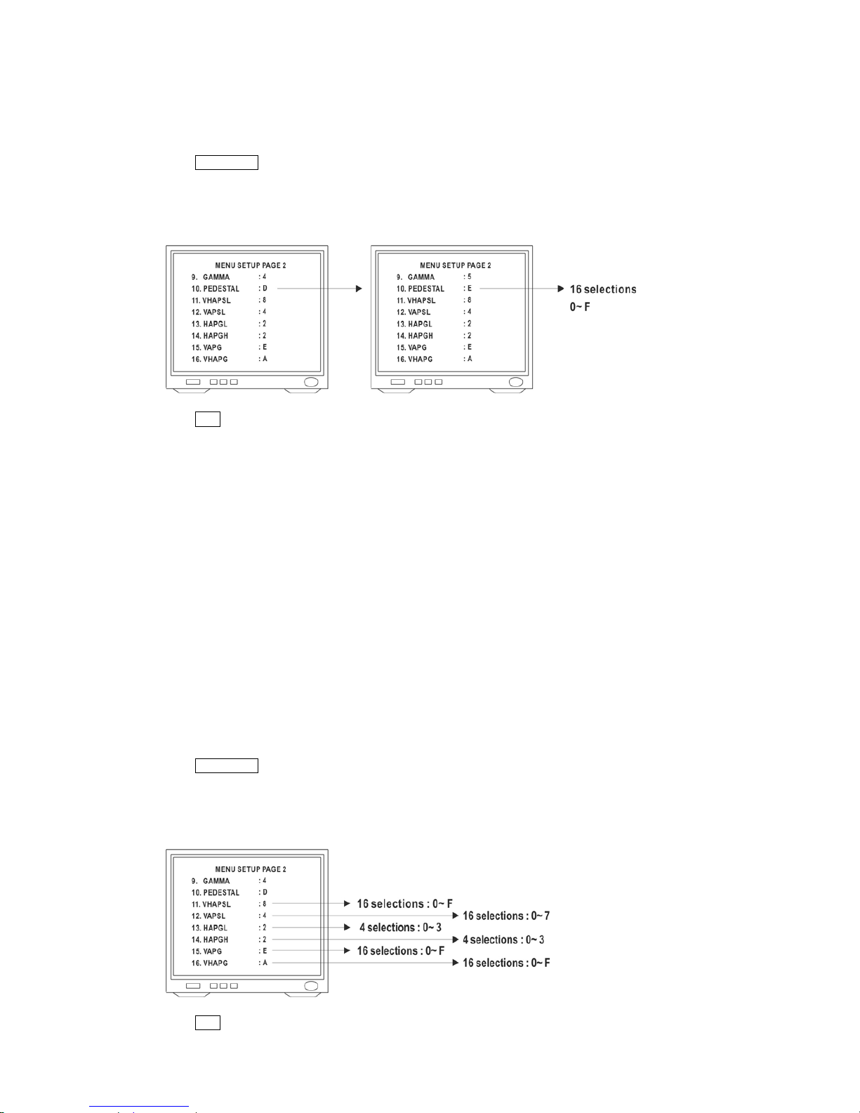
Pedestal Adjustment
16 levels of Pedestal can be adjusted. (Factory Default is D)
1. Click OSD(Enter) to recall OSD Setup Menu.
2. Click the Up or Down button to select 10th item "Pedestal" on menu.
3. Click Left or Right button to make selection : 0 ~ F
4. Click ESC button to exit menu, when finish or click Up or Down button to select next item.
Aperture Correction Adjustment
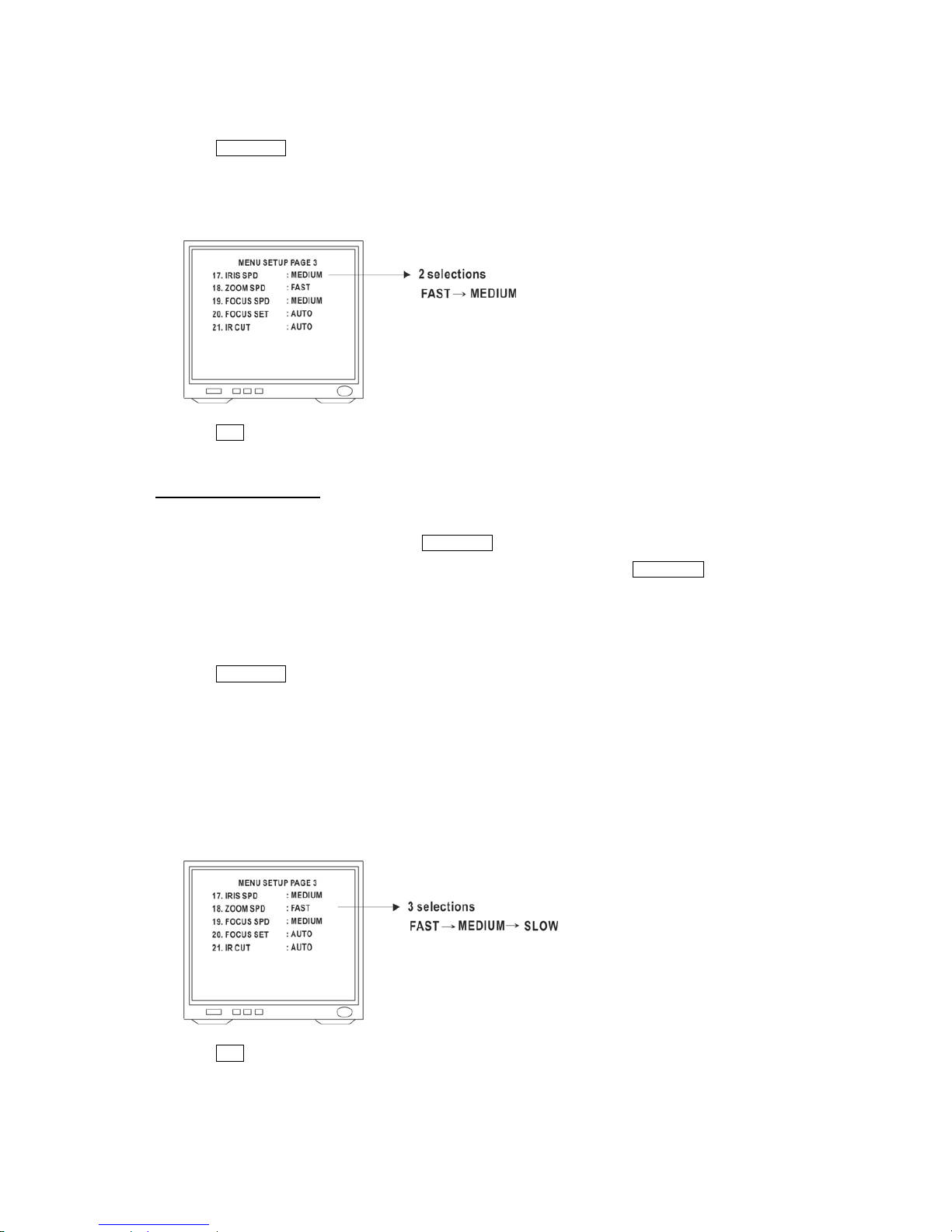
The 11th item to 16th item on the menu are different aperture correction function.
User can adjust the aperture correct level.
z 11. VHAPSL : Vertical & Horizontal Aperture Correction Slice level : 16 levels (Factory Default is 8)
z 12. VAPSL : Vertical Aperture Correction Slice level : 8 levels (Factory Default is 4)
z 13. HAPGL : Horizontal Aperture Correction (Low Band) Gain level : 4 levels (Factory Default is 2)
z 14. HAPGH : Horizontal Aperture Correction (High Band) Gain level : 4 levels (Factory Default is 2)
z 15. VAPG : Vertical Aperture Correction Gain Control : 16 levels (Factory Default is E)
z 16. VHAPG : Horizontal & Vertical Aperture Correction Gain : 16 levels (Factory Default is A)
1. Click OSD(Enter) to recall OSD Setup Menu.
2. Click the Up or Down button to select 11th ~ 16th items on menu.
3. Click Left or Right button to make selection.
4. Click ESC button to exit menu, when finish or click Up or Down button to select next item.
- 66 -
Page 68
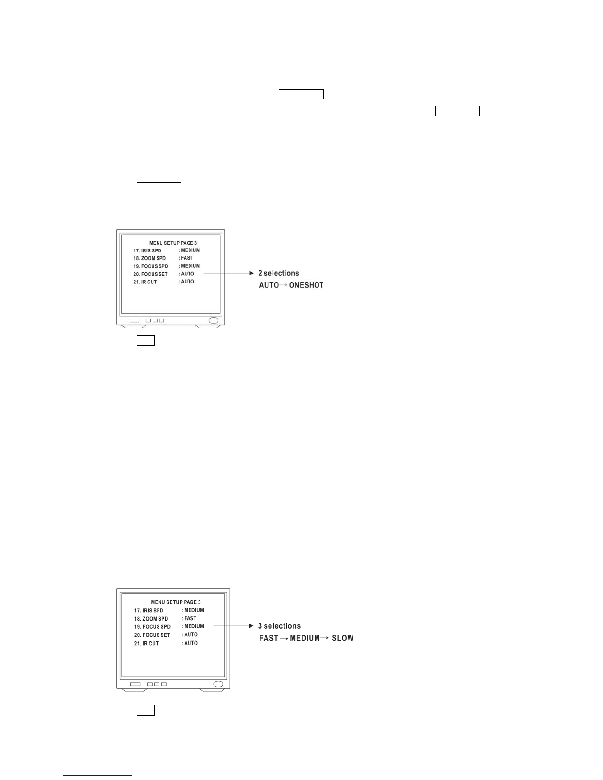
Manual Iris Speed Selection
1. Click OSD(Enter) to recall OSD Setup Menu.
2. Click the Up or Down button to select 17th item "Iris SPD" on menu.
3. Click Left or Right button to make selection: Fast -> Medium
4. Click ESC button to exit menu, when finish or click Up or Down button to select next item.
Manual Iris Speeds Switch
After above steps were completed, the selected manual iris speed is stored in the NDC. To use the selected manual
iris speed under lens control, user has to click Lens Speed button before operation, otherwise manual iris speed will be
"MEDIUM" as default. To switch back to "MEDIUM" manual iris speed simply click Lens Speed button again.
Manual Zoom Lens Control Speed Selection
1. Click OSD(Enter) to recall OSD Setup Menu.
2. Click the Up or Down button to select 18th item "Zoom SPD" on menu.
3. Click Left or Right button to make selection: Fast -> Medium -> Slow
z FAST = Tele - Wide : 3.5 seconds
z MEDIUM = Tele - Wide : 6 seconds
z SLOW = Tele - Wide : 52 seconds
4. Click ESC button to exit menu, when finish or click Up or Down button to select next item.
- 67 -
Page 69
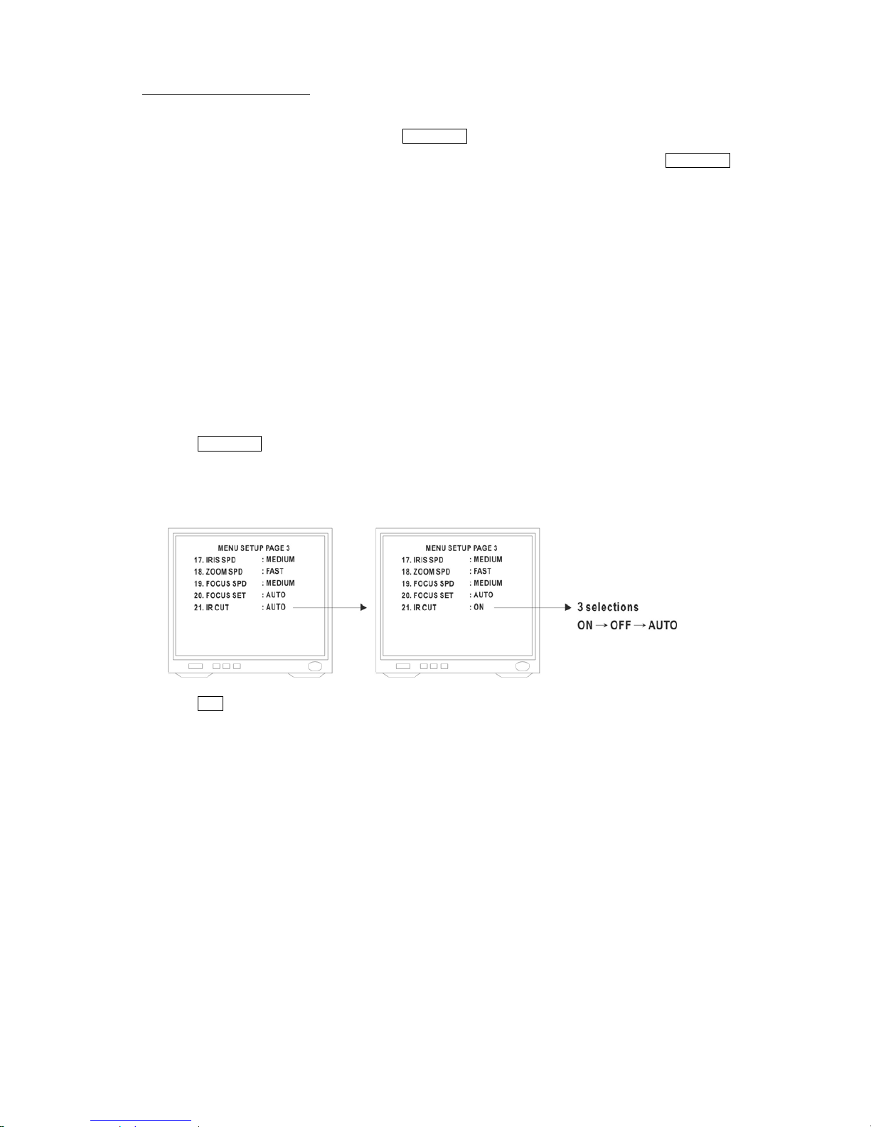
Manual Zoom Speeds Switch
After above steps were completed, the selected manual zoom speed is stored in the NDC. To use the selected manual
zoom speed under lens control, user has to click Lens Speed button before operation, otherwise manual zooming
speed will be "FAST" as default. To switch back to "FAST" manual zoom speed simply click Lens Speed button again.
Auto Focus & One Shot Focus Selection
1. Click OSD(Enter) to recall OSD Setup Menu.
2. Click the Up or Down button to select 20th item "Focus Set" on menu.
3. Click Left or Right button to make selection: Auto -> OneShot
4. Click ESC button to exit menu, when finish or click Up or Down button to select next item.
z After "Auto Focus" is selected, user has to click the arrow button beside “Auto Focus” to activate auto focus
function.
z After "One Shot" is selected, user has to click the arrow button beside “Auto Focus” to activate one shot auto
focus function.
When "One Shot Focus" is activated, the NDC will only auto "one shot" focus on object under Auto Panning or
Manual Zoom In/Zoom Out.
Manual Focus Speed Selection
1. Click OSD(Enter) to recall OSD Setup Menu.
2. Click the Up or Down button to select 19th item "Focus SPD" on menu.
3. Click Left or Right button to make selection: Fast -> Medium -> Slow
4. Click ESC button to exit menu, when finish or click Up or Down button to select next item.
- 68 -
Page 70
Manual Focus Speeds Switch
After above steps were completed, the selected manual focus speed is stored in the NDC. To use the selected manual
focus speed under lens control, user has to click Lens Speed button before operation, otherwise manual focusing
speed will be "MEDIUM" as default. To switch back to "MEDIUM" manual focus speed simply click Lens Speed again.
IR Cut Switch
One of three different IR Cut modes can be selected. (Factory Default is AUTO)
z AUTO : IR Cut filter auto switch according to Lux level. When light is over 5 Lux, IR Cut filter auto switch in and
produce color image. When light drops below 3 Lux, IR Cut filter auto switch out and produce monochrome image,
under monochrome mode sensitivity is increased to 0.01 Lux and can be use with IR lighting.
z ON : Always produce color images.
z OFF : Always produce monochrome images.
1. Click OSD(Enter) to recall OSD Setup Menu.
2. Click the Up or Down button to select 21st item "IR Cut" on menu.
3. Click Left or Right button to make selection: On -> Off -> Auto
4. Click ESC button to exit menu, when finish or click Up or Down button to select next item.
- 69 -
Page 71
6 Advanced Settings for UNC7825-OW
You can use the Web-based user interface to configure the most of functions for the UNC7825-OW. Some advanced
functions can be set via an on-screen display (OSD) setup menu.
6.1 Call Out the OSD Setup Menu
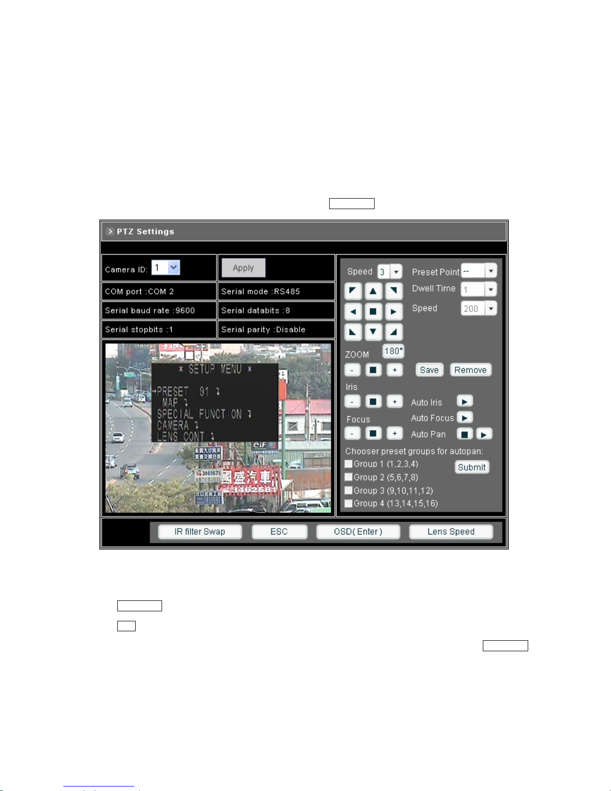
In Configuration > A/V Settings > PTZ Settings page, click on OSD(Enter) to call out the SETUP MENU.
You can use the following buttons on the OSD Setup Menu:
z Up, Down, Left and Right buttons: Move the cursor on the menu, or change the setting.
z OSD(Enter): Confirm the selection.
z ESC: Close and quit the SETUP MENU when in the first page.
z To quit from the other menu, position the cursor beside RET on the bottom of each page and click OSD(Enter).
- 70 -
Page 72
6.2 Special Functions
Display the Special Function Menu
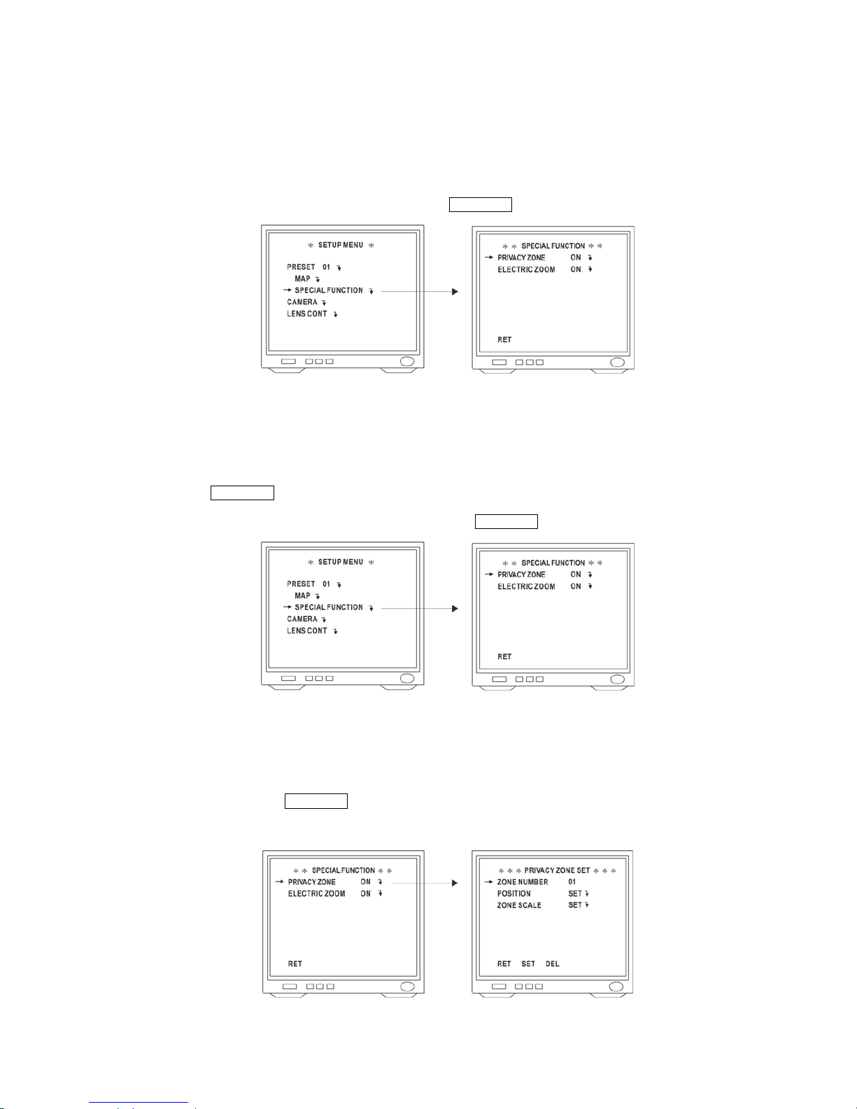
Position the cursor beside SPECIAL FUNCTION, and click OSD(Enter) to enter SPECIAL FUNCTION menu.
Privacy Zone
Up to 8 mask zones can be setup.
1. Click on OSD(Enter) to call out the SETUP MENU.
2. Position the cursor beside SPECIAL FUNCTION, and click OSD(Enter) to enter SPECIAL FUNCTION menu.
3. Position the cursor beside PRIVACY ZONE and select ON or OFF by clicking the Left or Right button.
ON : Mask zones are displayed.
OFF : Mask zones are disabled.
4. When select ON, click OSD(Enter) to display the PRIVACY ZONE SET menu.
5. Position the cursor beside ZONE NUMBER 01, click the Left or Right button to select a zone number.
- 71 -
Page 73
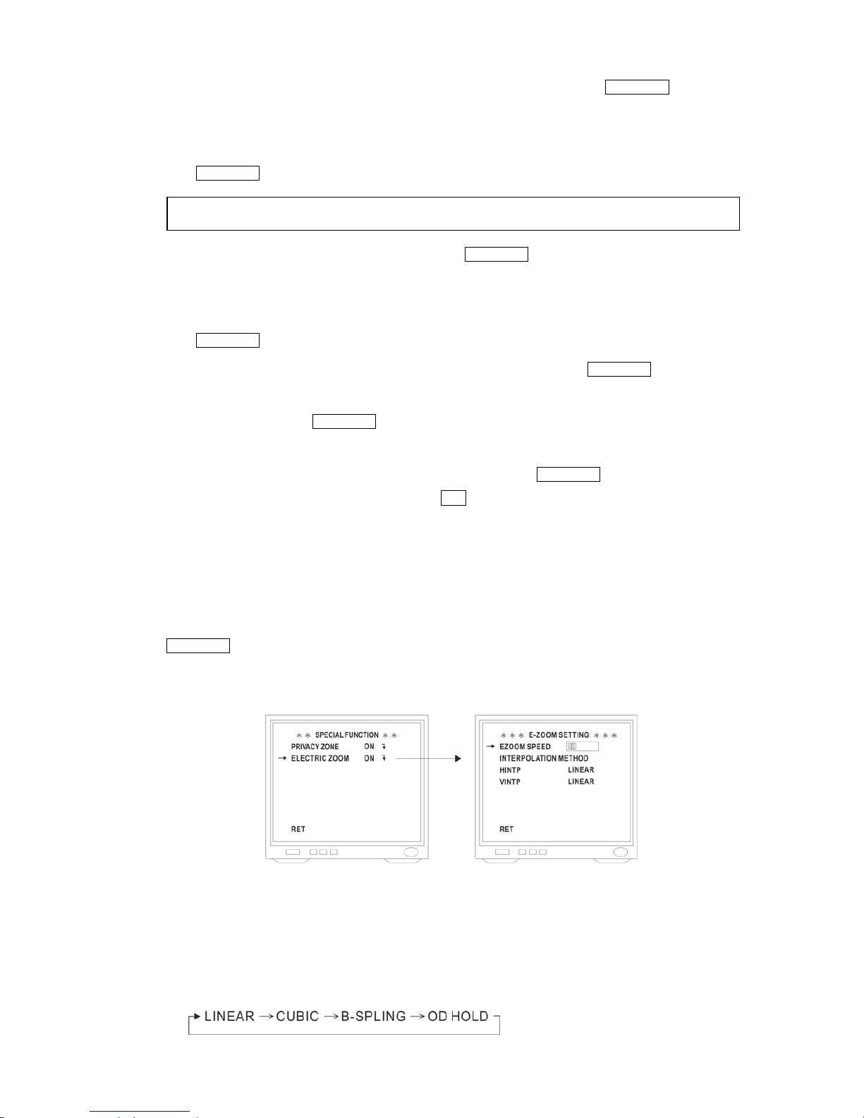
6. To set up a new privacy zone, position the cursor beside POSITION SET, and click OSD(Enter) to enter.
Select desired privacy zone by clicking the Up, Down, Left or Right button.
Adjust zoom and focus.
Click OSD(Enter) to save and return to the PRIVACY ZONE SET menu.
Note: When set up privacy zone, Zoom ratio can only be adjusted from 1X to 12X.
7. Position the cursor beside ZONE SCALE SET, and click OSD(Enter) to enter.
Click [Iris +] button and click the Up, Down, Right or Left button to increase the zone frame.
Click [Iris -] button and click the Up, Down, Right or Left button to decrease the zone frame.
Click OSD(Enter) to save and return to the PRIVACY ZONE SET menu.
8. To add or repeat another zone setting, position the cursor beside SET and click OSD(Enter) to save current
setting data.
9. If DEL is selected and click OSD(Enter), privacy zone setting is canceled and return to PRIVACY ZONE SET
menu.
10. After set up the privacy zone, position the cursor beside RET and click OSD(Enter). to quit from the current menu.
Repeat the above until SETUP MENU appear, click ESC to close the OSD Setup Menu.
Electric Zoom
The UNC7825-OW is with 2.56X electric zoom and 25X optical zoom for a 64X total zoom capacity.
z Position the cursor beside ELECTRIC ZOOM and select ON or OFF by clicking the Left or Right button, then click
OSD(Enter) to enter.
ON : 2.56X electric zoom is enabled with the ZOOM switch on the controller.
OFF : The electric zoom function is disabled.
z E-Zoom Speed Setting
Position the cursor beside EZOOM SPEED, click the Left or Right button to select desired E-Zoom speed.
z E-Zoom of Interpolation Method Setting
1. Position the cursor beside HINTP, click the Left or Right button to select the E-Zoom horizontal interpolation
method.
- 72 -
Page 74

2. Position the cursor beside VINTP, click the Left or Right button to select the E-Zoom vertical interpolation
method.
3. Position the cursor beside RET, click OSD(Enter) to return to SPECIAL FUNCTION menu.
Note:
z Linear interpolation
Interpolation signals are created between original signals using liner approximation. It provides images with
normal appearance.
z Cubic interpolation
The ideal LPF's impulse response is approximated by a curve, which is folded into the original signal to create
an interpolation signal. It provides images with increased resolution compared to linear interpolation.
z B-Spling interpolation
Interpolation signals are created using a curve which is joined by a smooth polynomial expression. It provides
images with a greater sense of smoothness than linear interpolation.
z 0-Order hold interpolation
The original signal is held and used as an interpolation signal, when the magnification is increased, mosaic
impression may appeared on the image.
- 73 -
Page 75
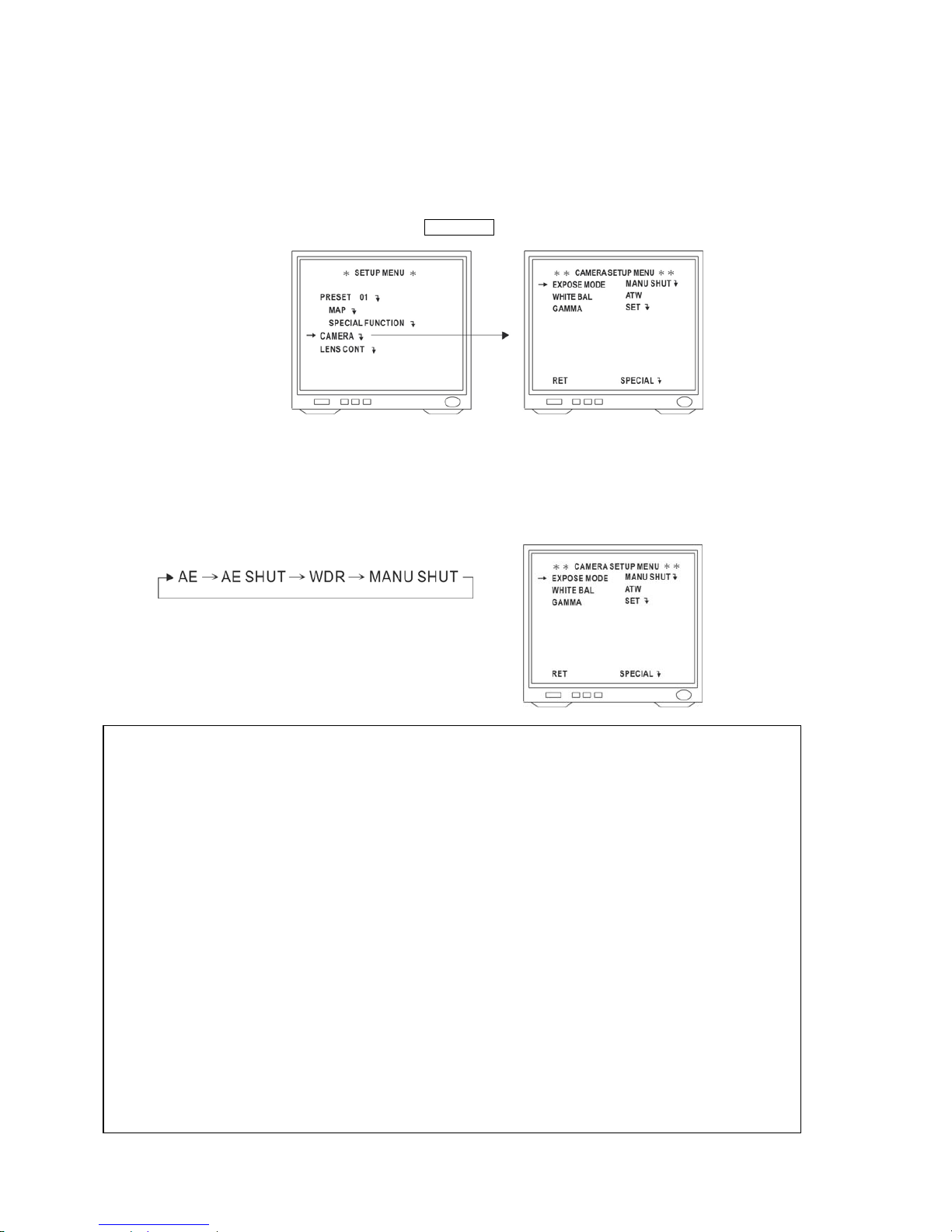
6.3 Camera Settings
Display the Camera Setting Menu
Position the cursor beside CAMERA and click OSD(Enter) to display Camera Setting Menu.
Expose Mode Setting
Position the cursor beside EXPOSE MODE and select an AE mode by clicking the Left or Right button.
Mode changes as follows:
Note:
EXPOSE MODE has four Exposure modes for selection. Each Exposure mode process electronic shutter differently
and is suitable for different environment.
z AE (Conventional)
Switches automatically between electronic shutter speed and the low-brightness zone control selected in LOW
Lux MODE to control the exposure time.
z AE Shut (AE SHUT)
The electronic shutter speed is fixed, while the mechanical iris and the low-brightness zone controls selected in
LOW Lux MODE are controlled automatically. The electronic shutter speed can be set manually.
z Wide Dynamic Range Control (WDR)
Use WD control, electronic shutter control, mechanical iris control, and the low-brightness zone controls
selected in LOW Lux MODE to control the exposure time automatically. Seamless switching between control
zones delivers shockless AE.
z Manual Shutter (MANU SHUT)
Electronic shutter speed is set up manually. The set value is fixed and it does not depend on luminance.
- 74 -
Page 76
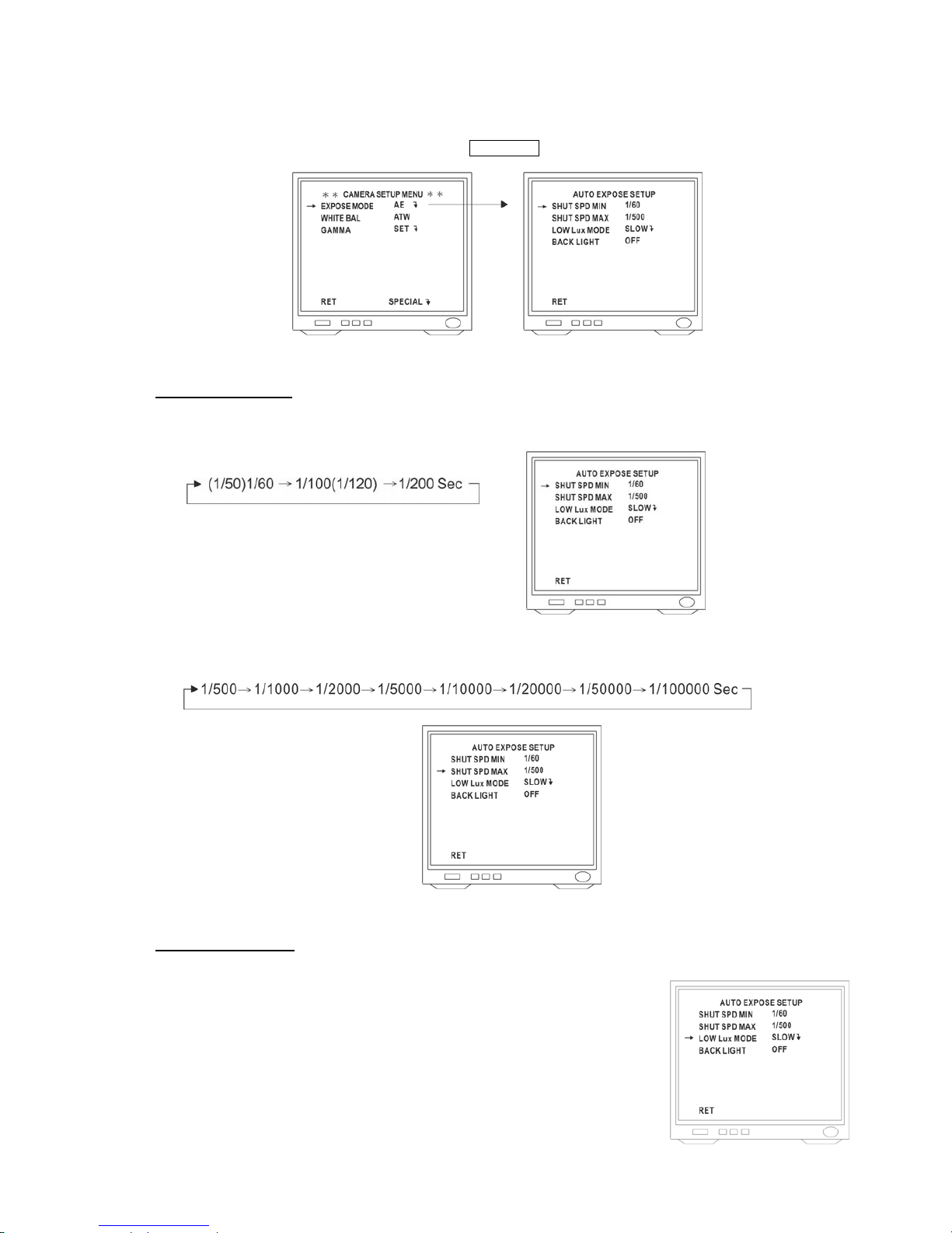
Expose Mode AE Setting
Position the cursor beside Expose Mode AE and click OSD(Enter) to enter Expose Mode AE
Shutter Speed Setting
1. Position the cursor beside SHUT SPD MIN and select minimum shutter speed by clicking the Left or Right button.
Mode changes as follows:
2. Position the cursor beside SHUT SPD MAX and select maximum shutter speed by clicking the Left or Right
button.
Low Lux Mode Setting
The purpose of Low Lux Mode parameters is to improve low-brightness zones that
make control of the electronic shutter and mechanical iris difficult.
Thus, under minimum shutter speed (UMS) can improve the situation.
Position the cursor beside LOW Lux Mode and select a field by clicking the Left or
Right button.
- 75 -
Page 77
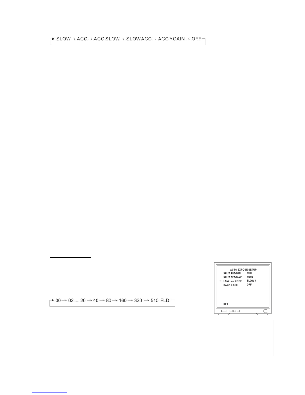
Mode changes as follows:
z OFF
Disable control in UMS zone.
z SLOW
Low-speed shutter control is activated when UMS zones are reached. As for the accumulated time when slow
control is initiated, the starting shutter speed is as set in LOW SHUTTER (Slow shutter maximum accumulation
time select) in the electric shutter control mode (EXPOSE MODE =WDR CONT, AE) or as selected in SHUTTER
(Manual shutter Speed Select) when electric shutter control is manual. For fixed-shutter flickerless operation, the
starting point is NTSC=1/100 or PAL=1/120.
z AGC
AGC control is activated when UMS zones reached. The maximum gain can also be switched among 3 gain
levels in AGC gain setting.
z AGC-Slow
Activates both AGC control and low-speed shutter control.
When UMS zones are set, AGC control is activated first, then switched to low-speed shutter control after the
maximum gain value reached.
z Slow-AGC
Activates both low-speed shutter control and AGC control.
When UMS zones are set, low-speed shutter control is activated first, then switched to AGC control after the
maximum number of stored fields reached.
z AGC-Ygain
Activates both AGC control and Y-gain control. When UMS zones are set, AGC control is activated first, then
switched to Y-gain control after the maximum gain value reached.
Slow Shutter Setting
Slow shutter control is activated when UMS reached.
Position the cursor is positioned beside Low Lux Mode.
Slow Shutter is available under SLOW, AGC SLOW and SLOWAGC mode
Slow-Speed Shutter Mode changes as follows:
Note:
The low-speed shutter control offers the optimal brightness level by increasing the number of stored fields of the
CCD in response to brightness level. Compared to AGC control, Low-Speed shutter offer less noise even in
conditions of low-brightness, but longer stored fields will lead to diminished dynamic resolution.
- 76 -
Page 78
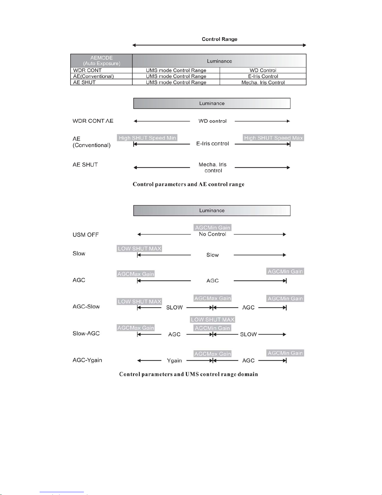
- 77 -
Page 79
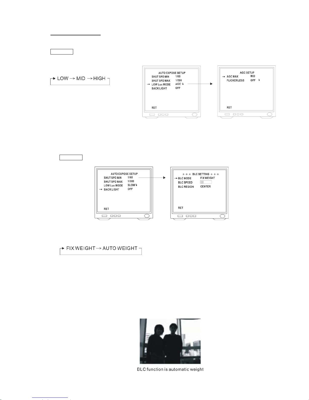
Auto Gain Control (AGC)
AGC control is activated when UMS reached. Set up AGC level by position the cursor beside Low Lux Mode and click
OSD(Enter) to enter.
Select a gain level by clicking the Left or Right button.
Level changes as follows:
LOW : Select lower gain control
MID : Select normal gain control
HIGH : Select higher gain control
Back Light Compensation Setting
1. Position the cursor beside BACK LIGHT and select ON or OFF by clicking the Left or Right button. Click
OSD(Enter) to display the BLC SETTING menu.
2. Position the cursor beside BLC MODE and select required back light compensation mode by clicking the Left or
Right button. Back light compensation mode changes as follows:
z Fixed weighting mode
Weighting values is fixed for each detection window, and backlight compensation is performed according to
these values.
z Automatic weighting mode
The weighting values are automatically controlled for backlight compensation in response to the light intensity
detection window.
- 78 -
Page 80
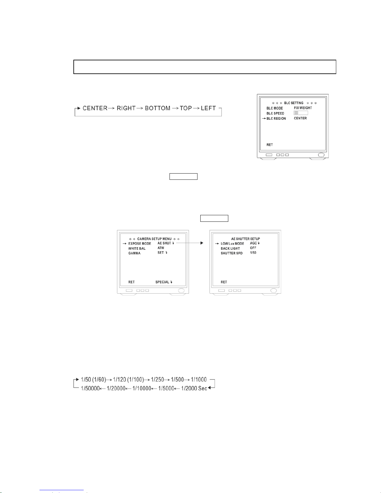
3. Position the cursor beside BLC SPEED and select the back light compensation converging speed by clicking the
Left or Right button.
Note: Increase the value will result in a faster converging speed.
4. Position the cursor beside BLC REGION and select the back light compensation converging region by clicking the
Left or Right button. Region changes as follows :
5. Position the cursor beside RET and click OSD(Enter) to return to CAMERA SETUP MENU.
Expose Mode AE Shutter Setting
Position the cursor beside Expose Mode AE Shut and click OSD(Enter) to enter Expose Mode AE SHUT.
1. Position the cursor beside LOW Lux MODE and select a field by clicking the Left or Right button. See page 64 ~
66 for detailed setup.
2. Position the cursor beside BACK LIGHT and select ON or OFF by clicking the Left or Right button. See page 67,
68 for detailed setup.
3. Position the cursor beside SHUTTER SPD and select shutter speed by clicking the Left or Right button.
Shutter Speed Mode changes as follows :
- 79 -
Page 81
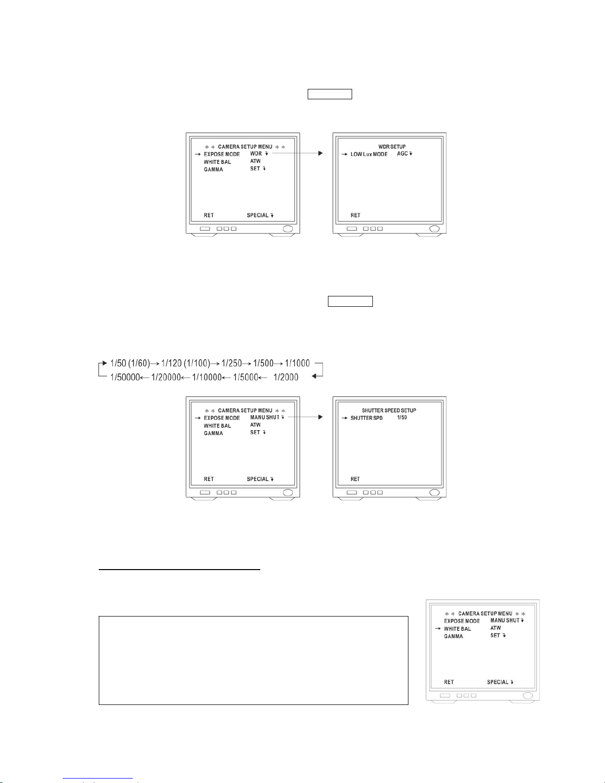
Expose Mode WDR Setting
Position the cursor beside Expose Mode WDR and click OSD(Enter) to enter WDR.
Select a field by clicking the Left or Right button. See page 64 ~ 66 for detailed setup.
Expose Mode Manual Shutter Setting
Position the cursor beside Expose Mode Manu Shut and click OSD(Enter) to enter Expose Mode MANU SHUT.
Select shutter speed by clicking the Left or Right button.
Shutter Speed Mode changes as follows :
White Balance Setting (WHITE BAL)
Auto-Tracing White Balance Mode (ATW)
Position the cursor beside WHITE BAL and select ATW by clicking the Left or Right button. The white balance of
camera is automatically set.
Note:
ATW is a feed forward system that automatically aligns the white balance by
detecting the R, G and B before WB amplifier.
The color temperature range for proper white balance is approximately
2500-9500K.
- 80 -
Page 82
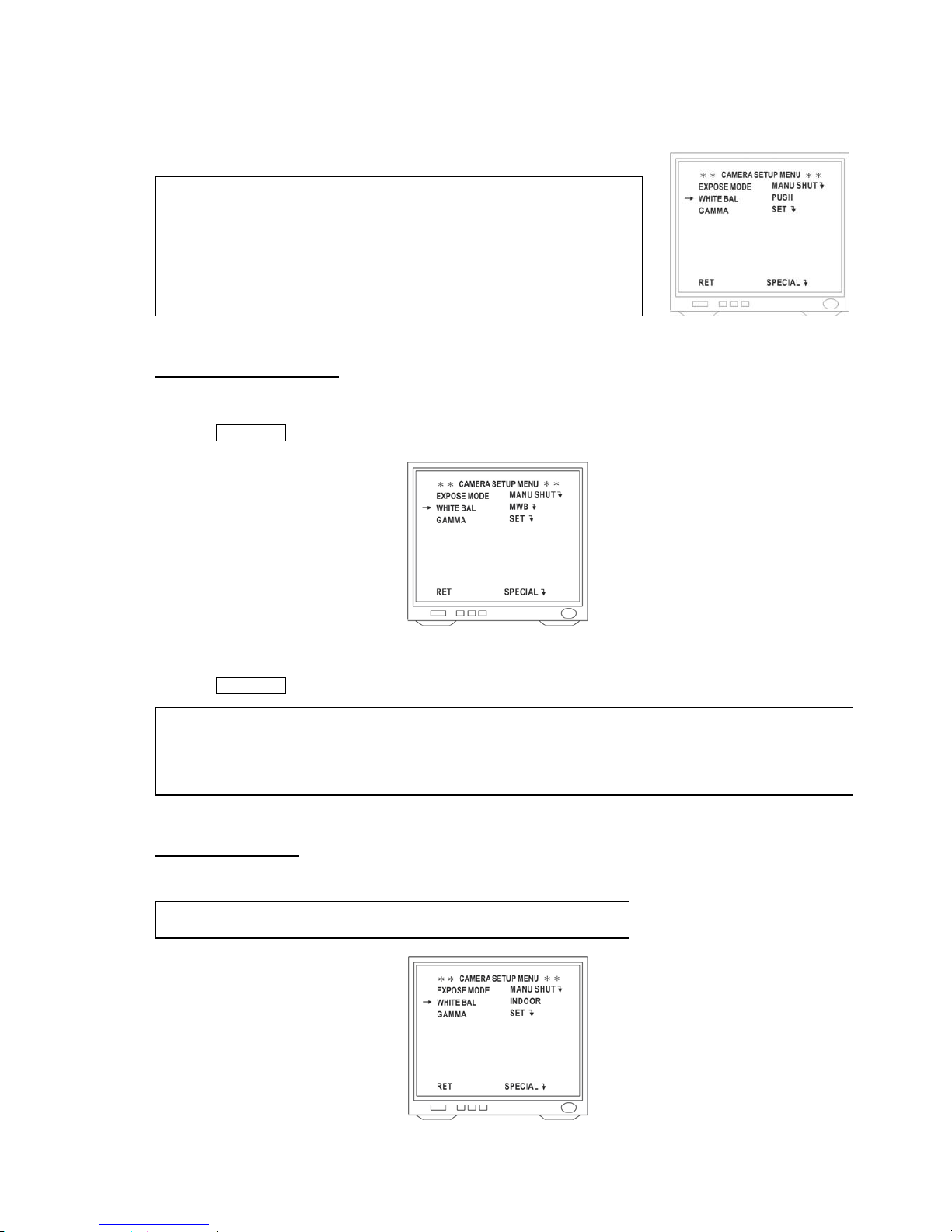
Push Mode (PUSH)
Position the cursor beside WHITE BAL and select PUSH by clicking the Left or Right button. The white balance of
camera is automatically set.
Note:
Operation is performed at a faster operating speed than ATW without an
operation frame or other limitation.
The color temperature range for proper white balance is approximately
2300-10000K.
Manual White Balance (MWB)
1. Position the cursor beside WHITE BAL and select MWB by clicking the Left or Right button.
2. Click OSD(Enter) to enter MWB Setting.
3. Click [Iris +] button to shift to higher color temperature and click [Iris -] button to shift to lower color temperature.
4. Click OSD(Enter) to return to CAMERA SETUPMENU.
Note:
z The adjustable color temperature range is from approximately 2500K to approximately 9500K.
z When the button is released after adjustment, the gain at that point is programmed into the EEPROM.
Indoor Mode (INDOOR)
Position the cursor beside WHITE BAL and select INDOOR by clicking the Left or Right button.
Note: In indoor mode the color temperature is fixed at approximately 3200K.
- 81 -
Page 83
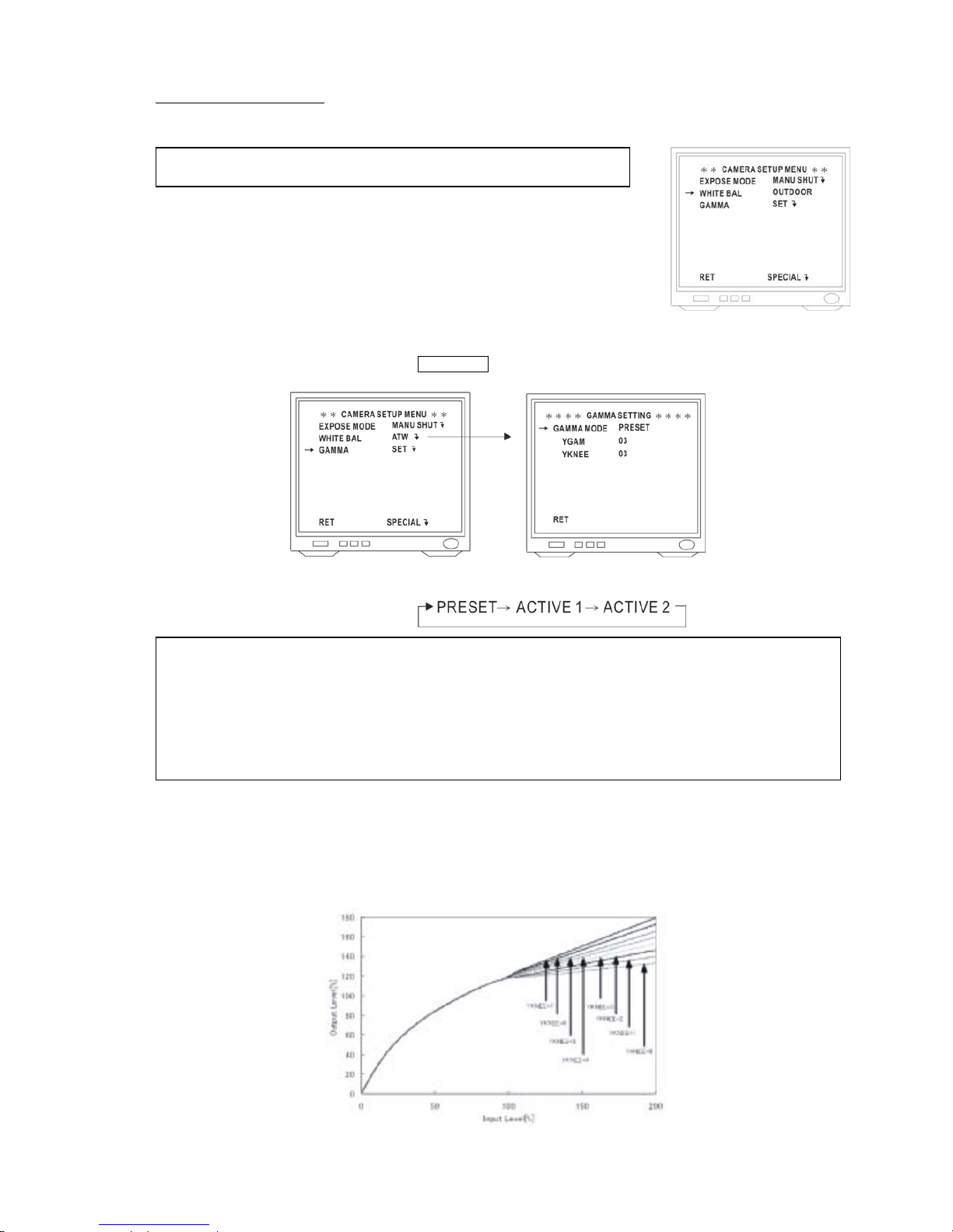
Outdoor Mode (OUTDOOR)
Position the cursor beside WHITE BAL and select OUTDOOR by clicking the Left or Right button.
Note: In outdoor mode the color temperature is fixed at approximately 6300K.
Gamma Function Setting
Position the cursor beside GAMMA and click OSD(Enter) to display Gamma Setting Menu.
Position the cursor beside GAMMAMODE and select a gamma mode by clicking the Left or Right button.
Gamma Mode changes as follows:
z PRESET mode : pre-set gamma curves can be selected.
z Active 1 : the gamma curve is changed automatically from the Y Signal histogram. This mode is effective
when there is backlight.
z Active 2 : the gamma curve is changed automatically from the Y Signal histogram. This mode is effective to
improve contrast during Wide-D shooting.
z PRESET Mode
The gamma curve can be change using YGAM. In addition the KNEE can be changed using YKNEE.
Position the cursor beside YGAM. Adjust YGAM curve by clicking the Left or Right button.
Position the cursor beside YKNEE. Adjust YKNEE curve by clicking the Left or Right button.
- 82 -
Page 84
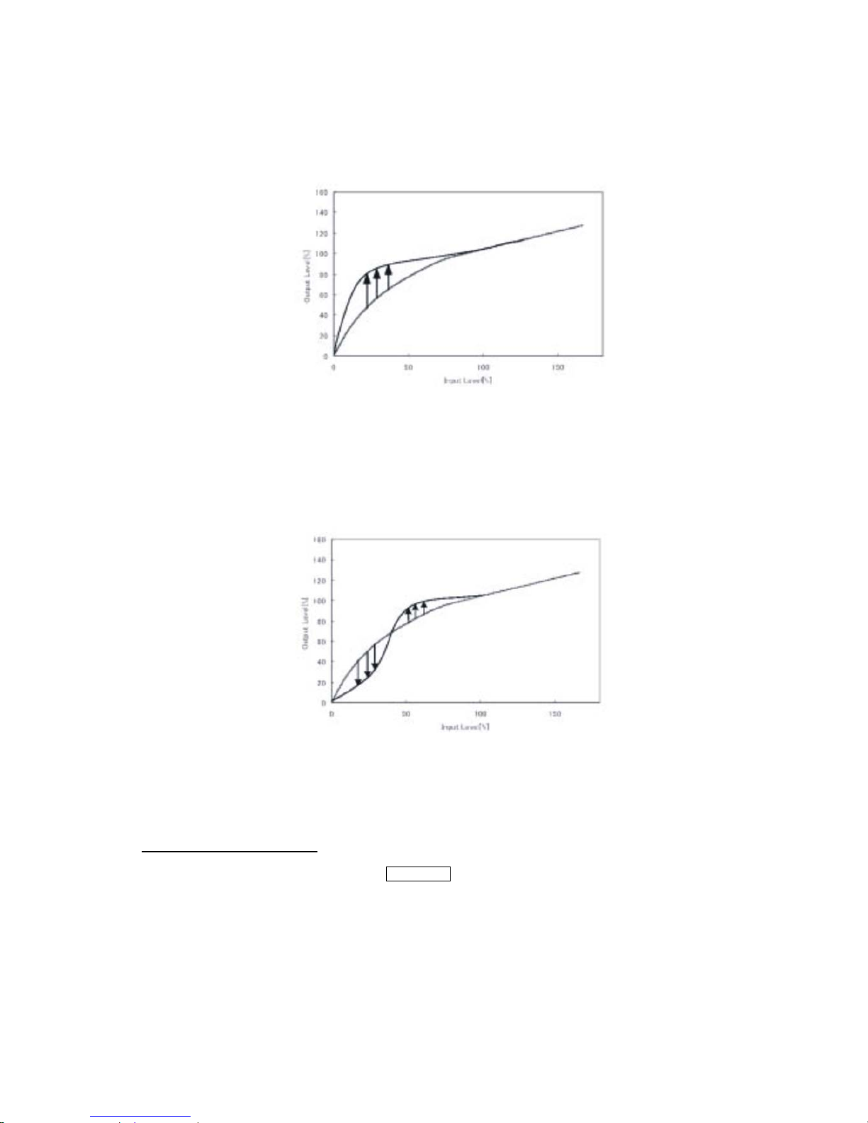
z Active 1 (Low Compensation)
Active 1 automatically raises the gamma curve in low areas according to the deviation in the brightness histogram.
In cases where there are significant brightness differences (e.g., backlight) and Wide-D processing is not
performed. (Input Level 100% of the following figures is the border of gamma and KNEE.)
z Active 2 (Contrast Improvement)
Active 2 automatically compresses the low areas of the gamma curve and raises the high areas according to the
brightness histogram. It is effective for flare control and improving contrast during Wide-D shooting. Note that if
this used without Wide-D shooting, black out on the image may occur depending on the shooting conditions.
(Input Level 100% of the following figures is the border of gamma and KNEE.)
Special Function Setting
Special Function Menu Display
Position the cursor beside SPECIAL and click OSD(Enter) to display Special menu.
- 83 -
Page 85
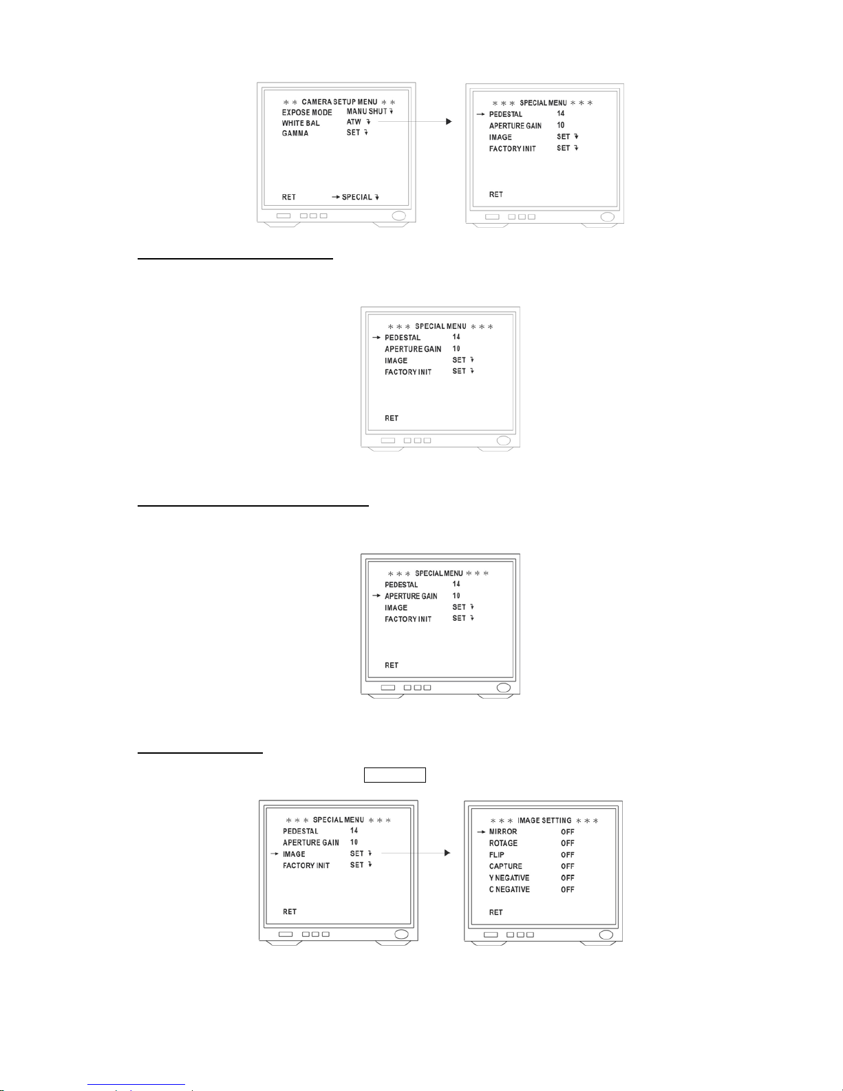
Pedestal Level Setting (PEDESTAL)
Position the cursor beside PEDESTAL, adjust the pedestal Level (black level) by clicking the Left or Right button.
Aperture Level Setting (APERTURE GAIN)
Position the cursor beside APERTURE GAIN, adjust the aperture level by clicking the Left or Right button.
Image Setting (IMAGE)
Position the cursor beside IMAGE and click OSD(Enter) to display Image Setting menu.
z MIRROR Function
Position the cursor beside MIRROR and select ON or OFF by clicking the Left or Right button.
- 84 -
Page 86
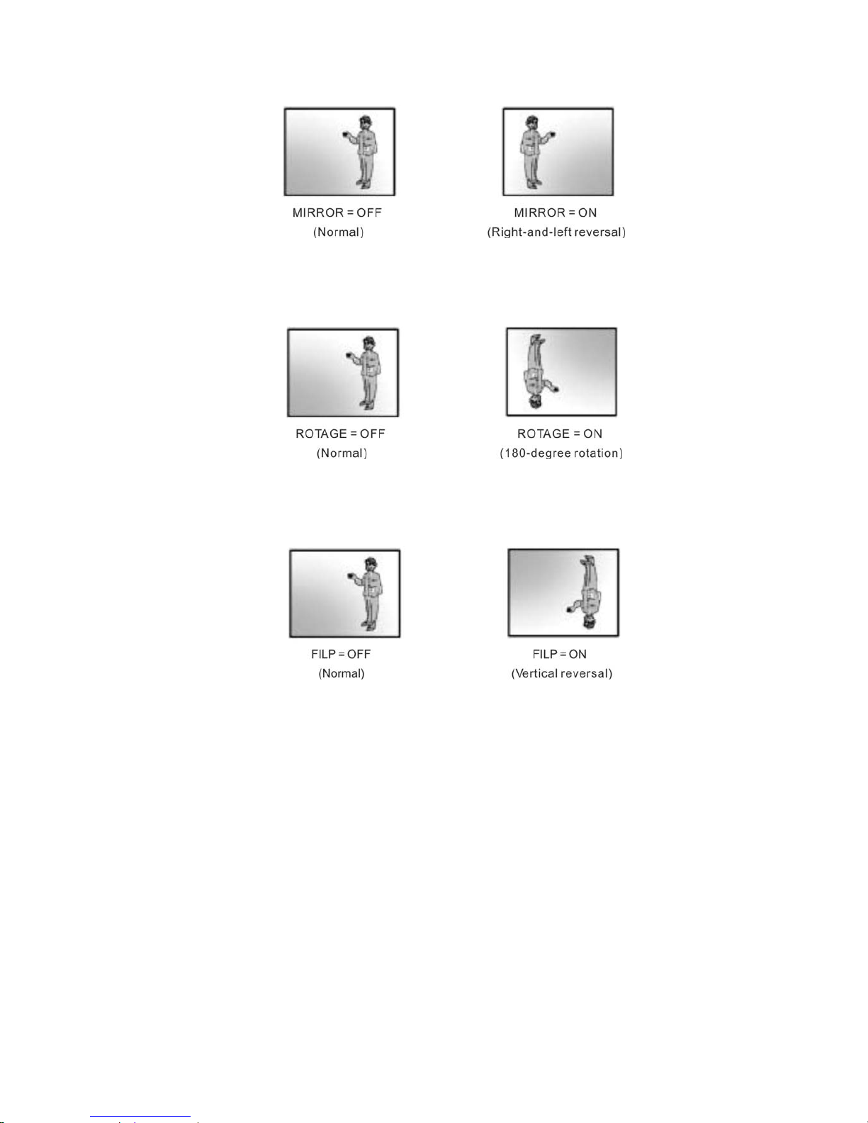
This mode reverses the left and right sides of the linear.
z ROTATE Function
Position the cursor beside ROTATE and select ON or OFF by clicking the Left or Right button.
This mode rotates the image 180 degrees.
z FLIP Function
Position the cursor beside FLIP and select ON or OFF by clicking the Left or Right button.
This mode reverses the top and bottom sides of the linear.
z Field image Capture (CAPTURE)
Position the cursor beside CAPTURE and select ON or OFF by clicking the Left or Right button.
ON: Freeze the field image.
OFF: disabled.
z Y negative function (Y NEGATIVE)
Position the cursor beside Y NEGATIVE and select ON or OFF by clicking the Left or Right button.
This function inverse the Y signal.
ON: Negative
OFF: Positive
z C negative function (C NEGATIVE)
Position the cursor beside C NEGATIVE and select ON or OFF by clicking the Left or Right button.
This function inverse the chroma signal.
ON: Negative
OFF: Positive
- 85 -
Page 87
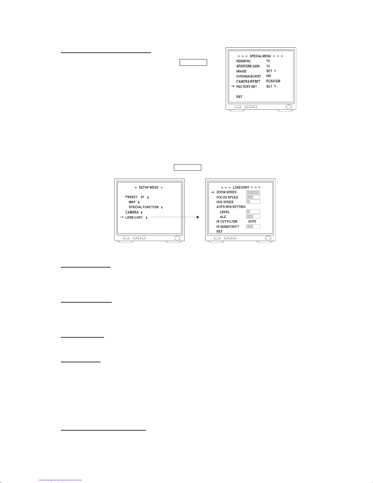
Factory Initialization (FACTORY INIT)
Position the cursor beside FACTORY INIT and click OSD(Enter).
The camera is reset to the factory preset parameters.
6.4 Lens Control
Display the Lens Control Menu
Position the cursor beside LENS CONT and click OSD(Enter) to display the Lens Control menu.
Zoom Speed Setting
Position the cursor beside ZOOM SPEED and clicking the Left or Right button to adjust zoom speed.
Focus Speed Setting
Position the cursor beside FOCUS SPEED and clicking the Left or Right button to adjust focus speed.
Iris Speed Setting
Position the cursor beside IRIS SPEED and clicking the Left or Right button to adjust iris speed.
Auto Iris Setting
z Level Setting
Position the cursor beside LEVEL and clicking the Left or Right button to adjust auto iris level.
z ALC Setting
Position the cursor beside ALC and clicking the Left or Right button to adjust ALC of auto iris.
IR Cut Filter Setting (ICR Function)
Position the cursor beside IR CUT FILTER and select IN, OUT or AUTO by clicking the Left or Right button.
- 86 -
Page 88
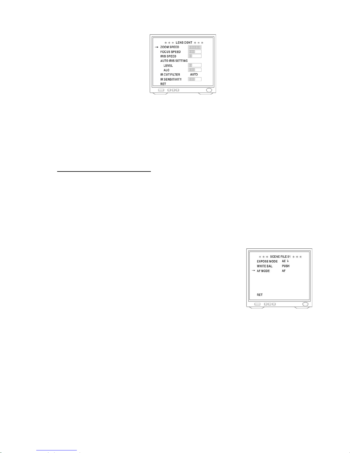
z IRF IN : IR Cut Filter is ON and always produce constant color image.
z IRF OUT : IR Cut Filter is OFF and always produce monochrome image.
z IRF AUTO : When light level is over 30 Lux, IR Cut Filter switches IN automatically to produce color image. When
light drops below 10 Lux, IR Cut Filter switches OUT automatically to produce monochrome image. Under
monochrome mode, sensitivity is increased to 0.01 Lux and can be used with IR illuminators.
IR SENSITIVITY Setting (IR SENSITIVITY)
Position the cursor beside IR SENSITIVITY, adjust the sensitivity for IR Cut In and IR Cut Out of IR Cut Filter under
auto mode by clicking the Left or Right button.
If setting the smaller value, only reaction when the light is very weak. On the other hand, IR Cut will be action.
Auto Focus Setting (AF MODE)
Position the cursor beside AF MODE and select AF or ONE SHOOT by clicking the
Left or Right button.
z AF : Continuous auto focus.
z ONE SHOOT : When ONE SHOOT AF is activated, Fast Dome will focus on t
object only once automatically under Auto Panning or manual Zoom IN / Zoom
OUT.
he
- 87 -
Page 89
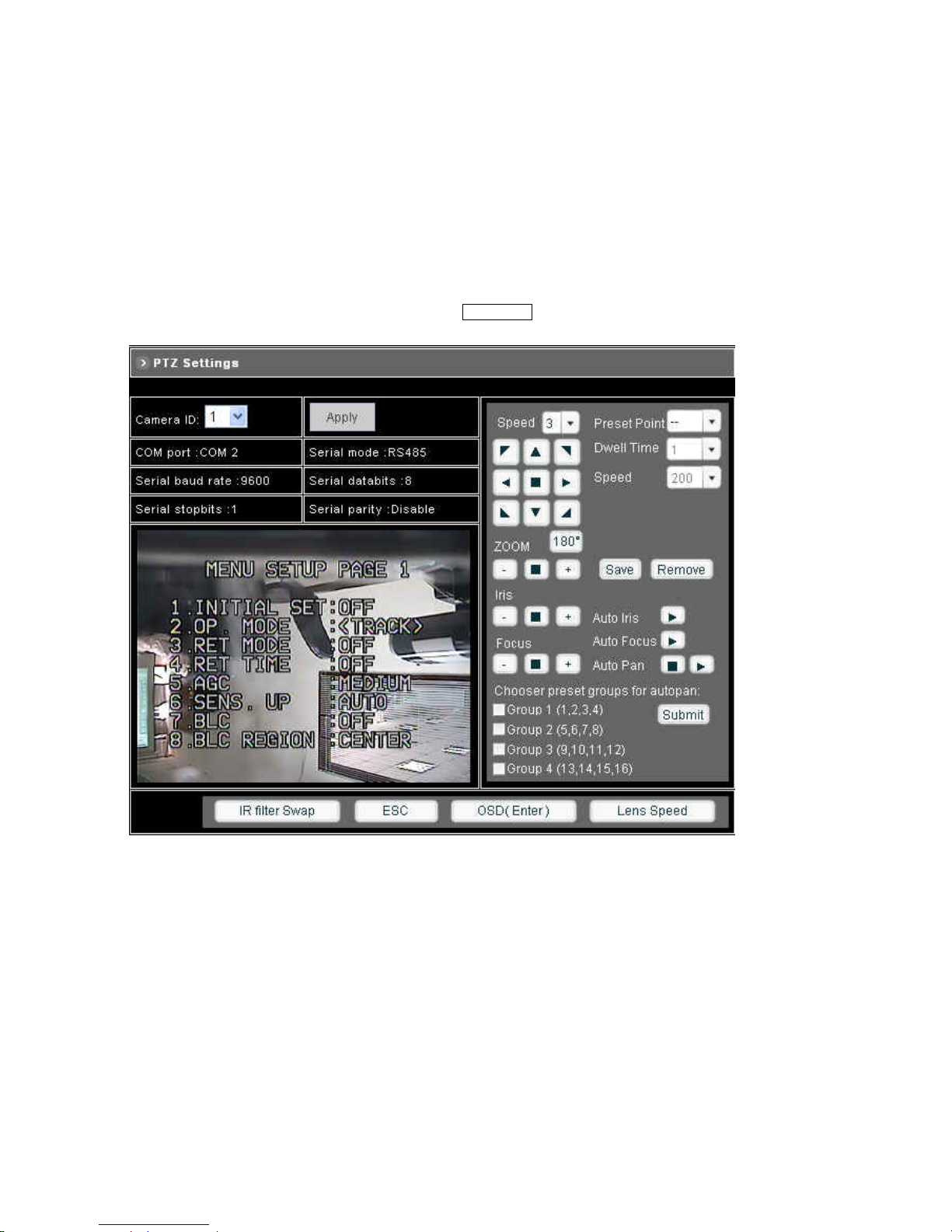
7 Advanced Settings for UNC7825-OT
You can use the Web-based user interface to configure the most of functions for the UNC7825-OW. Some advanced
functions can be set via an on-screen display (OSD) setup menu.
7.1 Call Out the OSD Setup Menu
In Configuration > A/V Settings > PTZ Settings, click OSD(Enter) to call out the SETUP MENU.
Function List
1. Factory Default
2. Operating mode (Normal or tracking)
3. RET Mode
4. RET Time
5. Auto GAIN Control
6. Sensitivity UP
7. BLC
8. BLC region
9. Flickerless
10. WB Mode
- 88 -
Page 90

11. WB Cont
12. Iris speed
13. Zoom speed
14. Focus speed
15. Focus set
16. ICR
17. Gamma
18. Pedestal
19. VHAPSL
20. VAPSL
21. HAPGL
22. HAPGH
23. VAPG
24. VHAPG
Setup Menu Item Selection
1. Click the DOWN button to select next item
2. Click the UP button to select previous item
3. Click the LEFT or RIGHT button to make selection
To Exit Setup Menu
Click ESC button, “Setup Initialize…” message will be displayed on the monitor for 4~5 seconds. All setting is stored in
the NDC.
- 89 -
Page 91
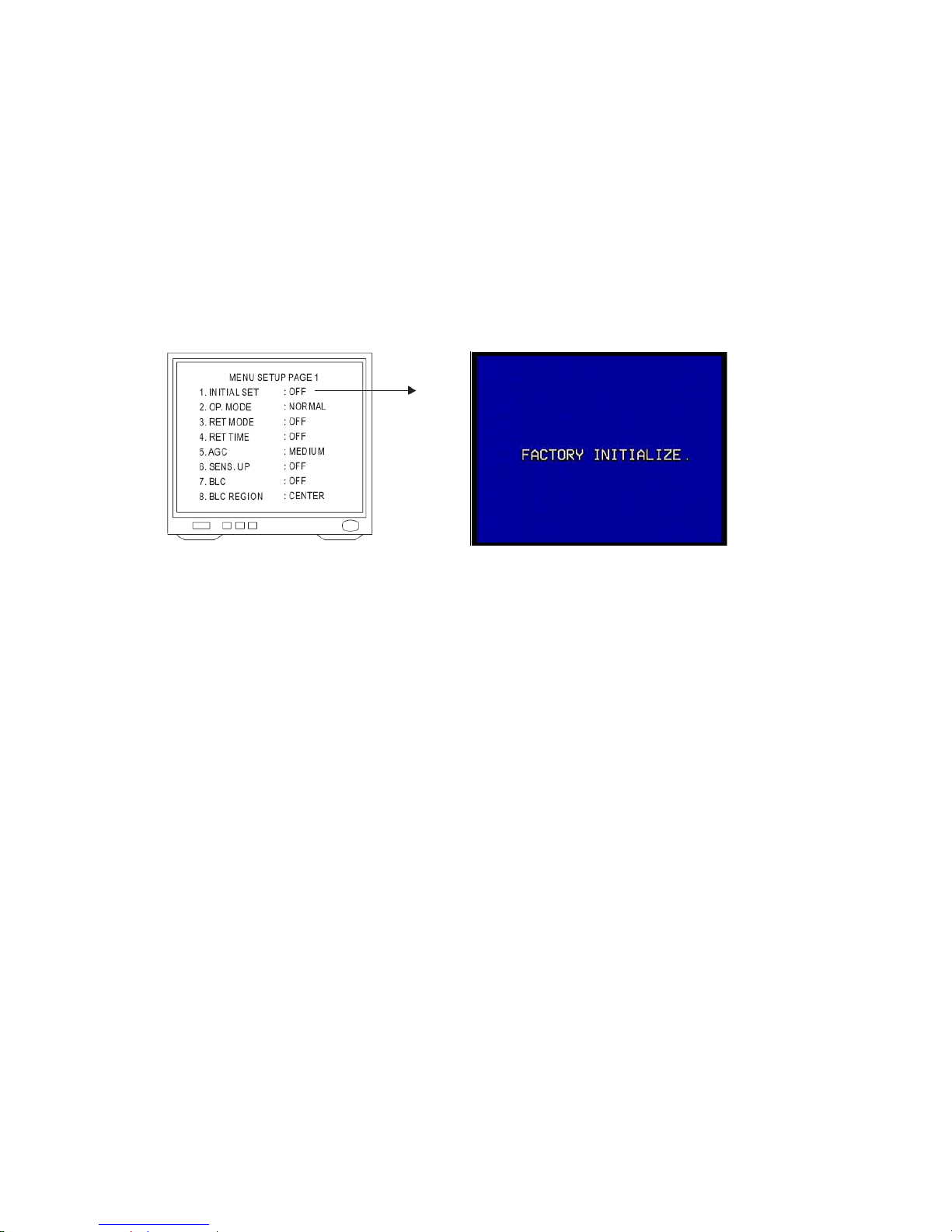
7.2 Setup Functions
Initial Setting (Factory Default)
To reset functions back to initial factory setting:
1. Click OSD(Enter) to recall OSD setup menu.
2. Click UP or DOWN button to select first option on menu and click LEFT or RIGHT button to make selection. Once
selected, “Factory Initialize…” message will be displayed on screen for 4~5 seconds.
3. When “Initialize” is done, monitor screen will switch back to setup menu.
4. Click ESC button to exit menu when finished or UP or DOWN button to select next item.
Operating Mode
There are two modes to choose from, normal and tracking. Under normal mode, NVC will only surveillance the chosen
area. Under tracking mode, NVC will keep following any moving object detected in the surveillance area.
1. Click OSD(Enter) to recall OSD Setup Menu.
2. Click the Up or Down button to select "OP. Mode" on menu.
3. Click Left or Right button to make selection: Normal -> Tracking
Under OP Mode: <TRACK>, press OSD(ENTER) for more options.
1. HOME POS: With auto-tracking on, when the moving object is out of range and the RET TIME is up, the device will
move back to preset-point (1~16). Here you could adjust the preset-point where the device will return to.
2. RET TIME: With auto-tracking on, when the moving object is out of range and the RET TIME is up, the device will
move back to preset-point (1~16). Could adjust from 1second to 50 seconds.
3. ZOM OPERATE: Enable the device to zoom in/out when tracking is on.
- 90 -
Page 92
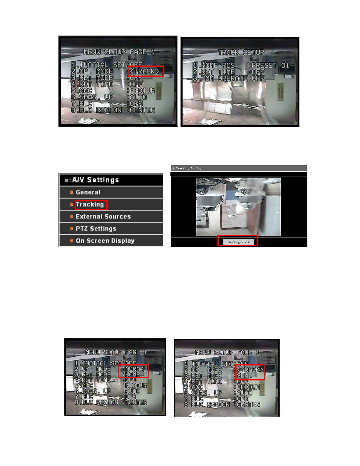
Another way to activate tracking mode is under configuration > A/V Settings > Tracking
Click on “Tracking On/Off” button to activate or deactivate tracking mode.
RET Mode
1. Click OSD(Enter) to recall OSD Setup Menu.
2. Click the Up or Down button to select "RET Mode" on menu.
3. Click Left or Right button to make selection: Off -> Home -> SEQ
Home: With tracking off, when the RET time is up, the device will move back to preset-point one.
SEQ: When RET time is up, the device will start auto-pan.
4. Click ESC button to exit menu when finished or click Up or Down button to select next item.
- 91 -
Page 93
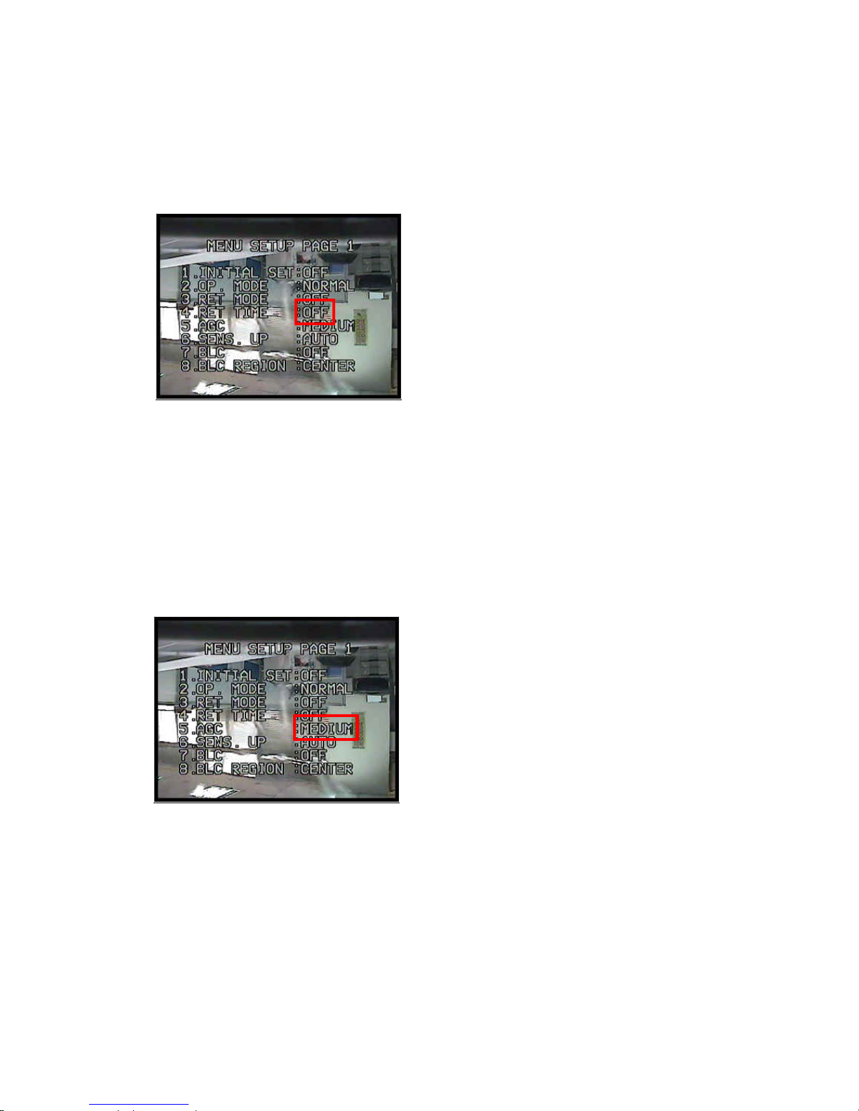
RET Time
1. Click OSD(Enter) to recall OSD Setup Menu.
2. Click the Up or Down button to select "RET Time" on menu.
3. Click Left or Right button to make selection: 1min -> 12hrs
4. Click ESC button to exit menu when finished or click Up or Down button to select next item.
Auto Gain Control
There are 3 different AGC levels can be selected. (Low = 8dB ; Medium = 22dB ; High = 36dB). Different AGC levels
may make different camera performance under low light environment. (Factory Default AGC is Medium).
1. Click OSD(Enter) to recall OSD Setup Menu.
2. Click the Up or Down button to select "AGC" on menu.
3. Click Left or Right button to make selection: Medium > Low > High
4. Click ESC button to exit menu when finished or click Up or Down button to select next item.
- 92 -
Page 94
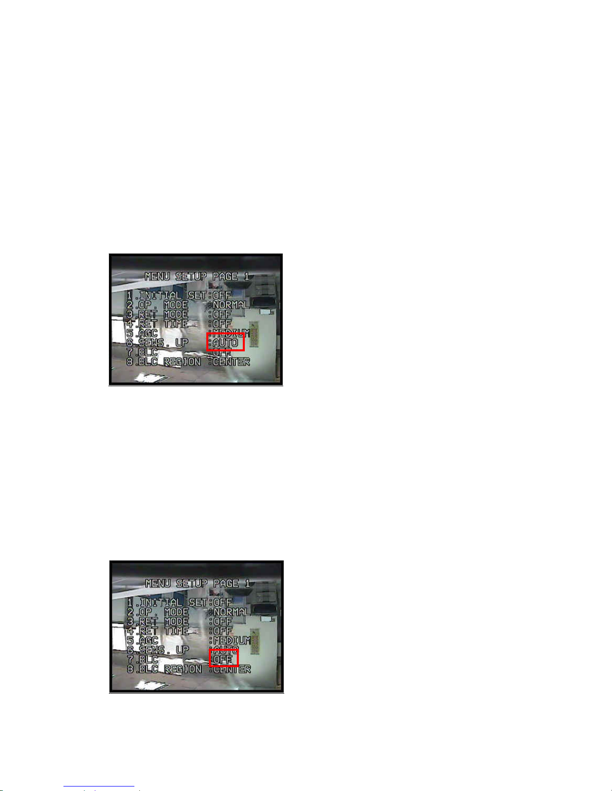
Sensitivity Up (Enhancement)
Sensitivity Up function allows user to select different Video Gain (Y Gain) control. (Factor Default is AUTO).
z AUTO: System auto turn on or off Video Gain Control function according to target's brightness.
z ON: Video Gain Control Enhancement always on.
z OFF: Video Gain Control Enhancement always off.
1. Click OSD(Enter) to recall OSD Setup Menu.
2. Click the Up or Down button to select 3rd item "SENS UP" on menu.
3. Click Left or Right button to make selection: Auto > On > Off
5. Click ESC button to exit menu when finished or click Up or Down button to select next item.
Back Light Compensation
Back Light Compensation can be turned on or off. (Factory Default is OFF)
1. Click OSD(Enter) to recall OSD Setup Menu.
2. Click the Up or Down button to select "BLC" on menu.
3. Click Left or Right button to make selection: Off -> On
Note: When "ON" is selected, BLC zone will be showed on monitor screen.
4. Click ESC button to exit menu when finished or click Up or Down button to select next item.
- 93 -
Page 95
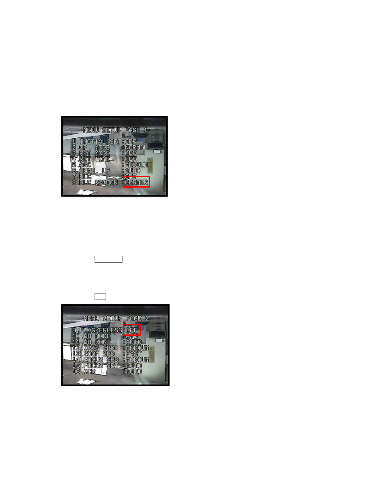
Back Light Compensation Region
There are five different regions to choose from for BLC: Top, bottom, left, right and center. (Default is center)
1. Click OSD(Enter) to recall OSD Setup Menu.
2. Click the Up or Down button to select "BLC Region" on menu.
3. Click Left or Right button to make selection: Center > Top > Bottom > Left > Right
6. Click ESC button to exit menu when finished or click Up or Down button to select next item
Flickerless
Flickerless function can be turned on or off. (Default is OFF). When "ON" is selected, Shutter Speed will be fixed at
1/100 sec in NTSC or fixed at 1/120 sec in PAL.
1. Click OSD(Enter) to recall OSD Setup Menu.
2. Click the Up or Down button to select 6th item "Flickerless" on menu.
3. Click Left or Right button to make selection : On -> Off
4. Click ESC button to exit menu, when finish or click Up or Down button to select next item.
- 94 -
Page 96
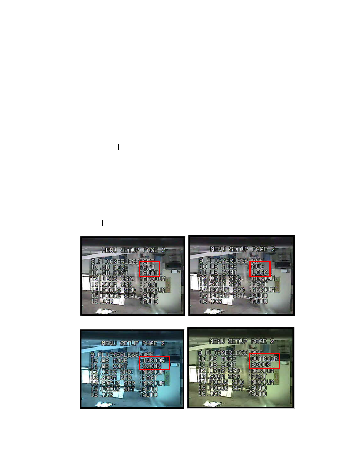
White Balance Mode Selection
One of four different White Balance Modes can be selected. (Factory Default is ATW)
z ATW: Auto Trace White Balance, is a feedback system that automatically aligns the white balance by detecting the
R-G and B-G before gamma correction processing.
z AWC: Auto White Balance Correction, is performed at a faster operating speed than ATW without an operation or
other limitations.
z Indoor: Fix mode White Balance, suitable for 3200K color temperature environment.
z Outdoor: Fix mode White Balance, suitable for 6400K color temperature environment.
1. Click OSD(Enter) to recall OSD Setup Menu.
2. Click the Up or Down button to select "WB Mode" on menu.
3. Click Left or Right button to make selection: ATW -> AWC -> Indoor -> Outdoor
Note : When AWC is selected, "Lock" will be showed under "WB Cont".
When Indoor is selected, "3200K" will be showed under "WB Cont".
When Outdoor is selected, "6400K" will be showed under "WB Cont".
When ATW is selected, "Auto" will be showed under "WB Cont".
4. Click ESC button to exit menu, when finish or click Up or Down button to select next item
- 95 -
Page 97
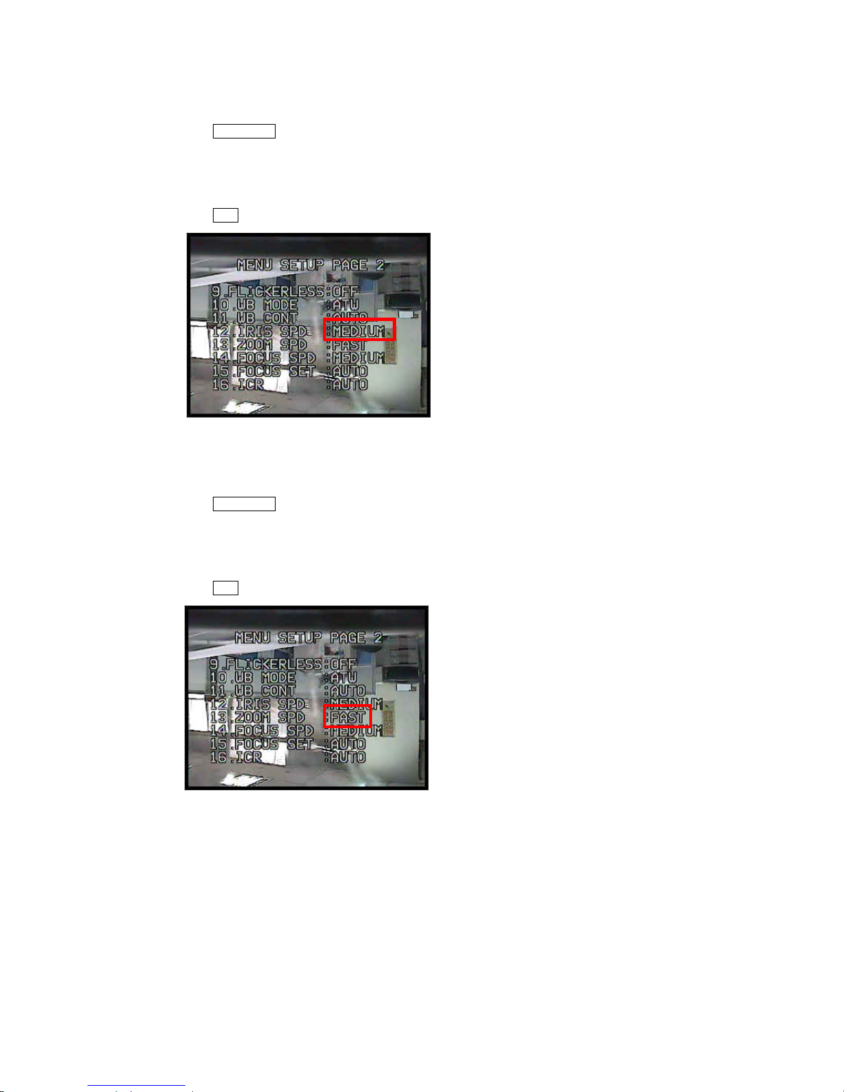
Iris Speed
1. Click OSD(Enter) to recall OSD Setup Menu.
2. Click the Up or Down button to select "Iris spd" on menu.
3. Click Left or Right button to make selection : Medium -> Fast
4. Click ESC button to exit menu, when finish or click Up or Down button to select next item
Zoom Speed
1. Click OSD(Enter) to recall OSD Setup Menu.
2. Click the Up or Down button to select "Zoom spd" on menu.
3. Click Left or Right button to make selection: Fast -> Slow -> Medium
4. Click ESC button to exit menu, when finish or click Up or Down button to select next item
- 96 -
Page 98
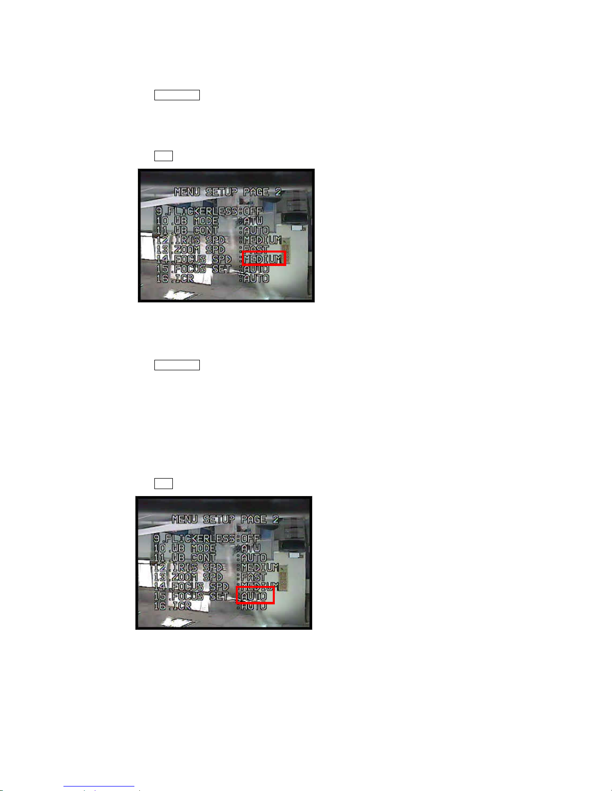
Focus Speed
1. Click OSD(Enter) to recall OSD Setup Menu.
2. Click the Up or Down button to select "Focus Spd" on menu.
3. Click Left or Right button to make selection: Medium -> Fast -> Slow
4. Click ESC button to exit menu, when finish or click Up or Down button to select next item
Focus Set
1. Click OSD(Enter) to recall OSD Setup Menu.
2. Click the Up or Down button to select "Focus Set" on menu.
3. Click Left or Right button to make selection: Auto -> OneShot
z Auto: Continuous focus
z OneShot: Dome will focus on the object only once automatically under auto panning or manual zoom
in/out.
4. Click ESC button to exit menu, when finish or click Up or Down button to select next item
- 97 -
Page 99
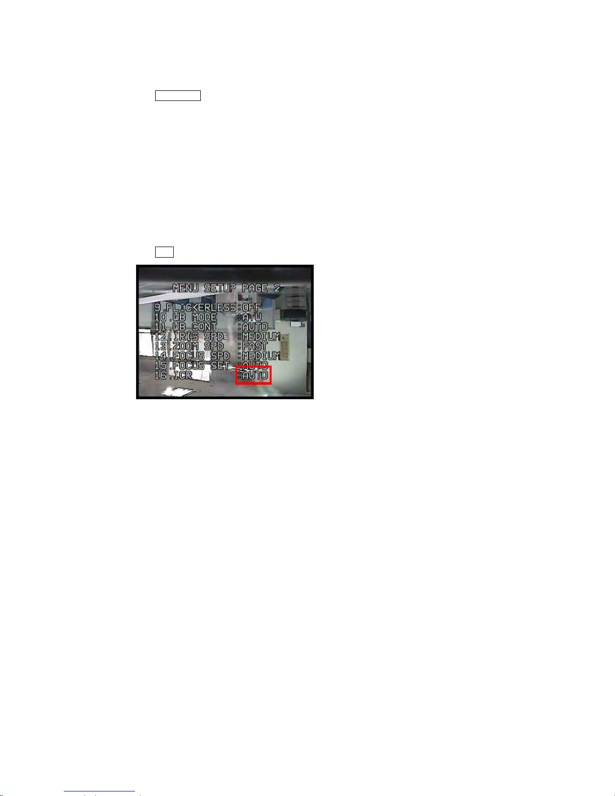
ICR
1. Click OSD(Enter) to recall OSD Setup Menu.
2. Click the Up or Down button to select "ICRt" on menu.
3. Click Left or Right button to make selection: Auto -> In -> Out
z Auto: When light level is over 30Lux, IR cut filter switches to IN automatically to produce color image. When
light drops below 10 Lux, IR cut filter switches to OUT automatically to produce monochrome image. Under
monochrome mode, sensitivity is increased to 0.01 Lux and can be used with IR illuminators.
z Out: IR cut filter is OFF and always produce monochrome image.
z On: Always produce color images.
4. Click ESC button to exit menu, when finish or click Up or Down button to select next item
- 98 -
Page 100
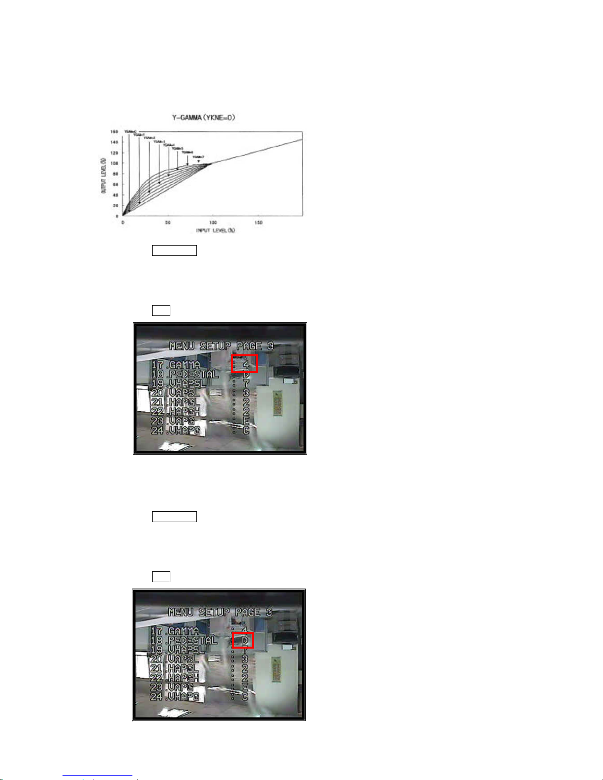
Gamma
8 levels of Gamma (Brightness) can be adjusted. (Factory Default is 4)
1. Click OSD(Enter) to recall OSD Setup Menu.
2. Click the Up or Down button to select "Gamma" on menu.
3. Click Left or Right button to make selection : 0 ~ 7
4. Click ESC button to exit menu, when finish or click Up or Down button to select next item.
Pedestal
16 levels of Pedestal can be adjusted. (Factory Default is D)
1. Click OSD(Enter) to recall OSD Setup Menu.
2. Click the Up or Down button to select "Pedestal" on menu.
3. Click Left or Right button to make selection: 0 ~ F
4. Click ESC button to exit menu, when finish or click Up or Down button to select next item.
- 99 -
 Loading...