

Page 1
Indoor Dual-Streaming
CCD Network Camera
UNC7702-Series User’s Manual
Version: 1.0
Date: 05/030/2008
Copyright EUSSO Technologies, Inc. All rights reserved
Page 2

CONTENTS
CHAPTER 1 INTRODUCTION..................................................................................................................................... 2
1. WHAT IS DUAL STREAMING NETWORK CAMERA/VIDEO SERVER?...................................................................2
2. FEATURES.........................................................................................................................................................3
CHAPTER 2 PHYSICAL IMAGES...............................................................................................................................4
UNC7702 NETWORK CAMERA.......................................................................................................................................4
CHAPTER 3 INSTALLATION.......................................................................................................................................5
1. HARDWARE CONNECTION.................................................................................................................................5
2. SOFTWARE INSTALLATION................................................................................................................................6
3. NETWORK CONFIGURATION .............................................................................................................................7
CHAPTER 4 USING THE WEB UI............................................................................................................................. 11
1. LIVE VIEW......................................................................................................................................................12
2. PLAYBACK...................................................................................................................................................... 15
3. CONFIGURATION PAGE....................................................................................................................................21
CHAPTER 5 CONFIGURE THE SETTINGS WITH WEB UI.................................................................................22
1. SUB ITEMS ...................................................................................................................................................... 22
2. VIDEO SETUP (AVAILA B LE FOR ADMINISTRATOR ONLY) .................................................................................23
3. CAMERA SETUP..............................................................................................................................................25
4. EVENT SETUP ................................................................................................................................................. 28
5. SYSTEM SETUP ...............................................................................................................................................34
6. NETWORK SETUP............................................................................................................................................39
7. STORAGE SETUP.............................................................................................................................................43
8. LOG LIST........................................................................................................................................................45
APPENDIX A SPECIFICATIONS................................................................................................................................46
APPENDIX B THE MINI-DIN CONNECTOR...........................................................................................................47
APPENDIX C FAQ.........................................................................................................................................................49
1. HOW CAN I SET FACTORY DEFAULT? ...............................................................................................................49
2. HOW TO UPGRADE FIRMWARE FOR THE DEVICE?.............................................................................................50
3. WHY ACTIVEX REMAINS IN OLD VERSION AFTER UPGRADING TO NEW VERSION FIRMWARE?.........................52
Page 3

2
Chapter 1
Introduction
1. What is Dual Streaming Network Camera/Video Server?
The UNC7702 (Network Camera, hereinafter called UNC7702) is professional MPEG-4/MJPEG dual
streaming surveillance products. Dual streaming allows seamless remote video monitoring using
MPEG-4 concurrently with transmission of high quality JPEG images to an optional storage. The audio
stream can also be compressed and distributed over Intranet/Internet as the result of capable being
recorded. UNC7702 has 2 USB 2.0 host ports; with external storage connected the video/au dio can be
recorded locally. For power solution, while normal adapter is applied for both devices the UNC7702 also
comes with an optional PoE model. The UNC7702 successfully provides the solution of remote
monitoring and quality recording in surveillance.
Page 4

3
2. Features
Self-Contained Web Server providing Internet capability for remote access
MPEG-4/MJPEG dual compression formats
Simultaneous MPEG-4 and MJPEG stream for multiple clients
Supports up to 30/25 FPS at Full D1 resolution
More than 540 TV lines resolution
Built-in internal microphone
Event handling trigger by alarm/motion and action to send video clip by Email / FTP
Two USB 2.0 Host ports support external storage connection for local recording
Wireless USB dongle (IEEE 802.11b/g) compliant (to be upgraded)
IP setup by easy IP Installer / DHCP / Static IP
Supports DDNS for dynamic IP application
NTP (network time server) with DST supported which provide accurate unify system time
Hardware watchdog providing robustness system in critical environment
Page 5
Chapter 2
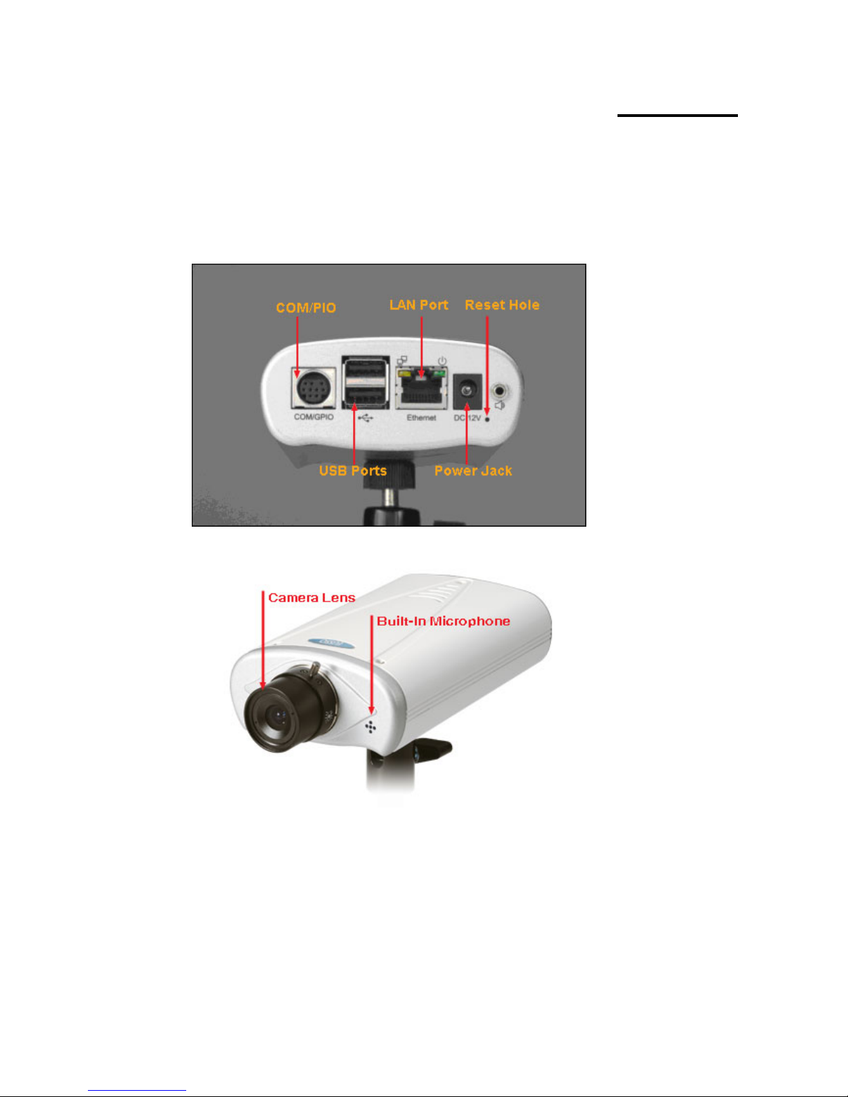
Physical Images
UNC7702 Network Camera
4
Page 6
Chapter 3
Installation
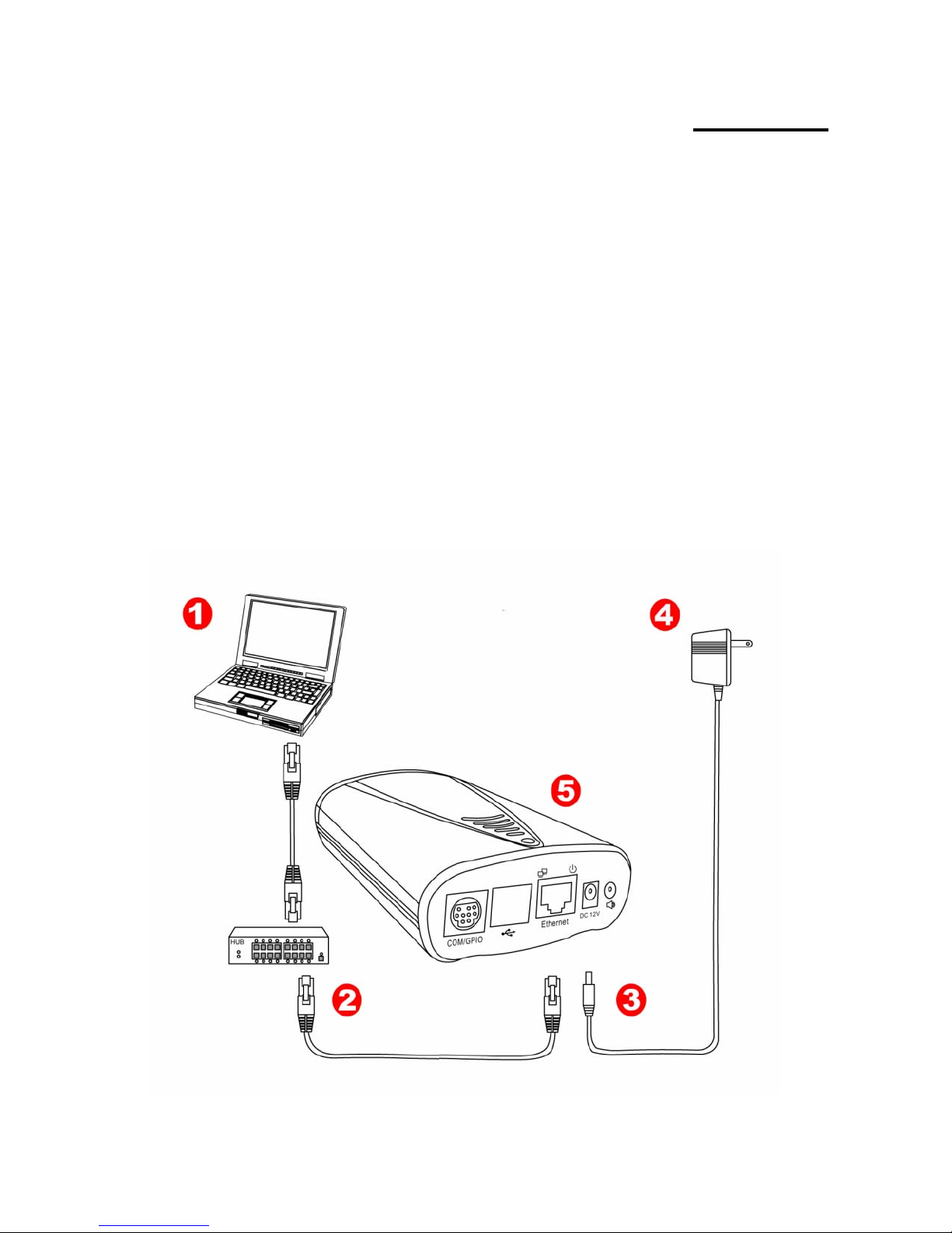
1. Hardware connection
1. Prepare a PC with Ethernet link to the network
2. Connect UNC7702 device to the network hub/switch with standard pass through (CAT5) cable,
or connect directly to PC with a cross over cable.
3. Connect power jack
4. Ensure the power adapter specification matches the power system (110V or 220V). Connect
the adapter to the outlet.
5. Check both LEDs (Power/Network); ensure they are light on after the ste ps above.
Follow the above steps to perform the UNC7702 connections.
Physical connection of UNC7702 Camera
5
5
Page 7

6
2. Software Installation
The following software is necessary for the proper display and use of the UNC7702 from the Web site.
The software will be taken from the Software Package CD.
IP Installer
The IP Installer is used to locate and configure n etwork cameras and video servers on the LAN. This
utility is useful for conveniently configuring the network settings of the device, or for finding a device
once the network settings have been modified.
To install the IP Installer, from the Sof t ware Package CD UI, select IP installer, then follow the on screen
instructions.
Component Installer
The ActiveX component is used by our device s for video display an d device configuration. Usually, when
you connect to the UNC7702 via IE browser, the ActiveX component will be installed automatically. If the
components can not be installed, inst all this software from the Software Package CD.
XVID Codec
An MPEG-4 codec is applied for displaying the video stream and playing the recoded AVI files. If the
video stream can’t be displayed or the recorded AVI files can be play on PC, install this software from the
Software Package CD.
VLC
Though not necessary, this can be used for viewing the streaming without a Web browser.
Page 8
7
t provides an easier, more efficient way to configure the IP address and network
ettings of the devices. It even provides a convenient way to set the network settings for multiple devices
aneously using the batch setting function. Moreover, IP Installer can save the network settings for
reparation before IP As signment
3. Network Configuration
IP Installer is a utility tha
s
simult
all devices as a backup and restore them when necessary.
P
. Always consult your network administrator before assigning an IP address to your server in order to
avoid using a previously assigned IP address.
2. Ensure the UNC7702 is powered on and correctly connected to the network.
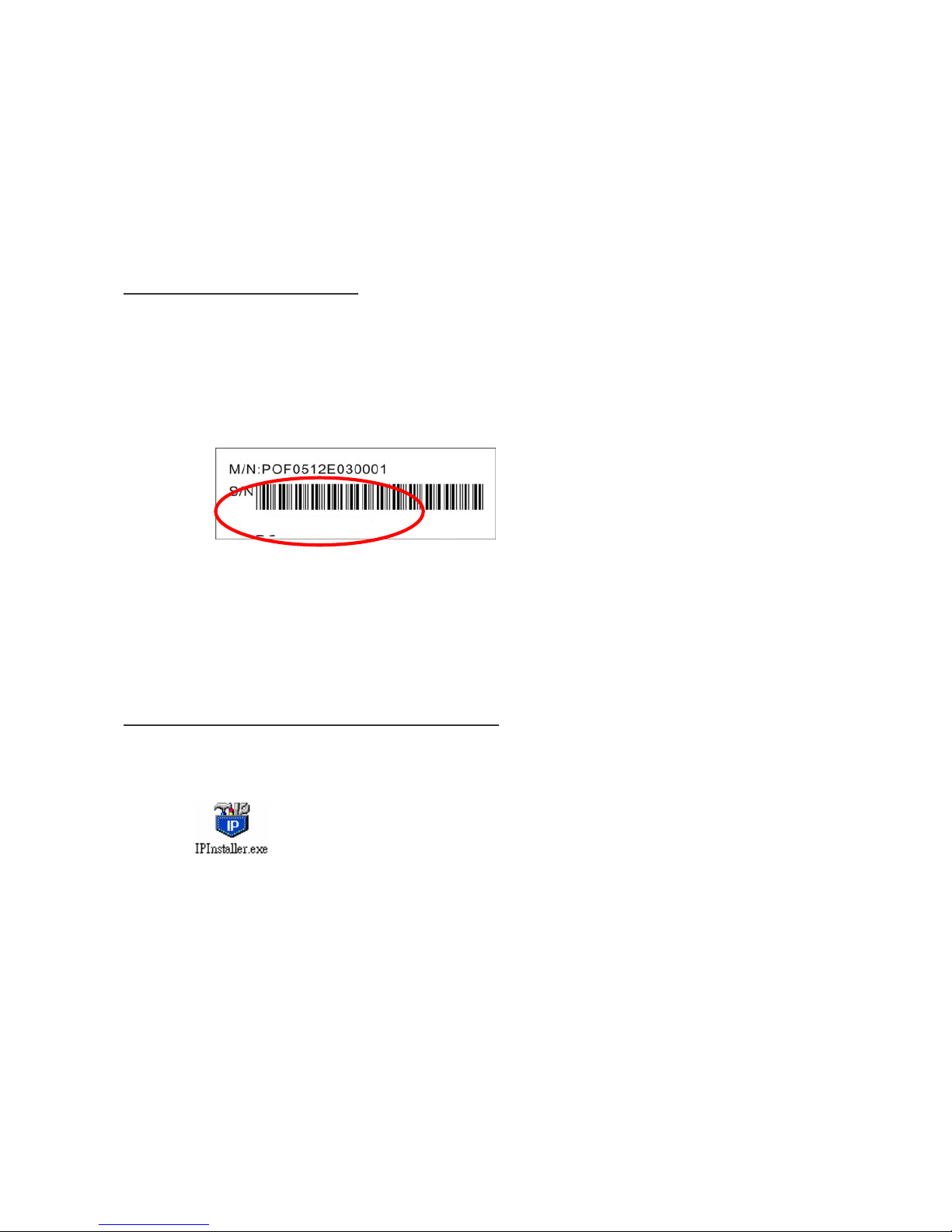
3. MAC Address: Each device has a unique Ethernet address (MAC address) shown on the label of the
device as the serial number (S/N) with 12 digits (e.g. 000429-XXXXXX).
1
4. Although the IP Installer is able to find and configure any UNC7702 on the LAN except those that are
behind a router, it is a good idea to set the host PC to the same subnet. In order to connect to the
Web-based user interface of UNC7702, the host PC must be in the same sub net. For more information
about subnets, please consult your network administrator.
Using IP Installer to Assign an IP Address to UNC7702
1.
Once IP Installer has been successfully inst alled on the PC, double click the IP Installer icon on the
desktop, or select it from Start > Programs > IP Installer > IP Installer > Launch IP Installer.
*0004290000
Page 9
8
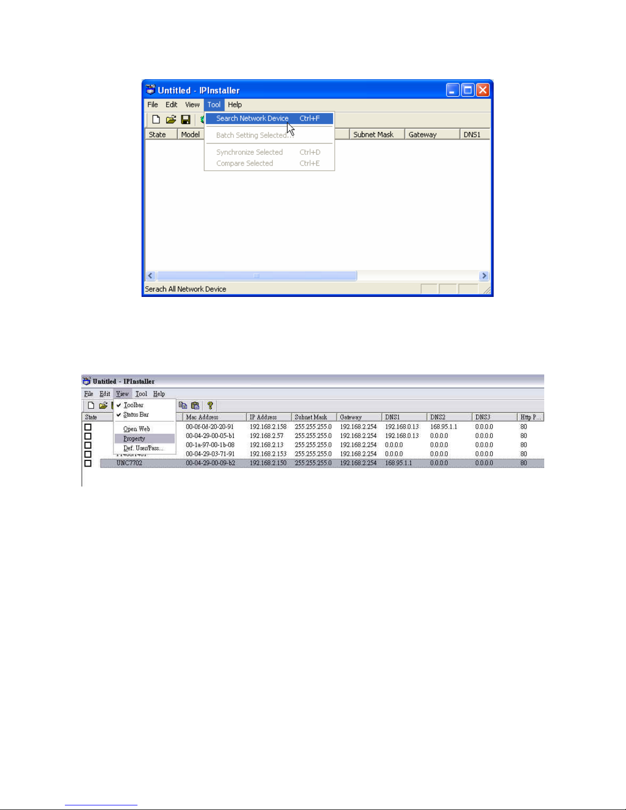
work Device to search the device in the LAN. 2. Click the menu bar Tool > Search Net
3. From the list, select the device with the MAC Address that corresponds to the UNC7702 that is to be
configure l to the unit’s S/N (Serial Number).
4. Double cli erty Page for e selected device or click the menu bar View >
d. The MAC Address is identica
ck the item to open the Prop th
Property.
Page 10
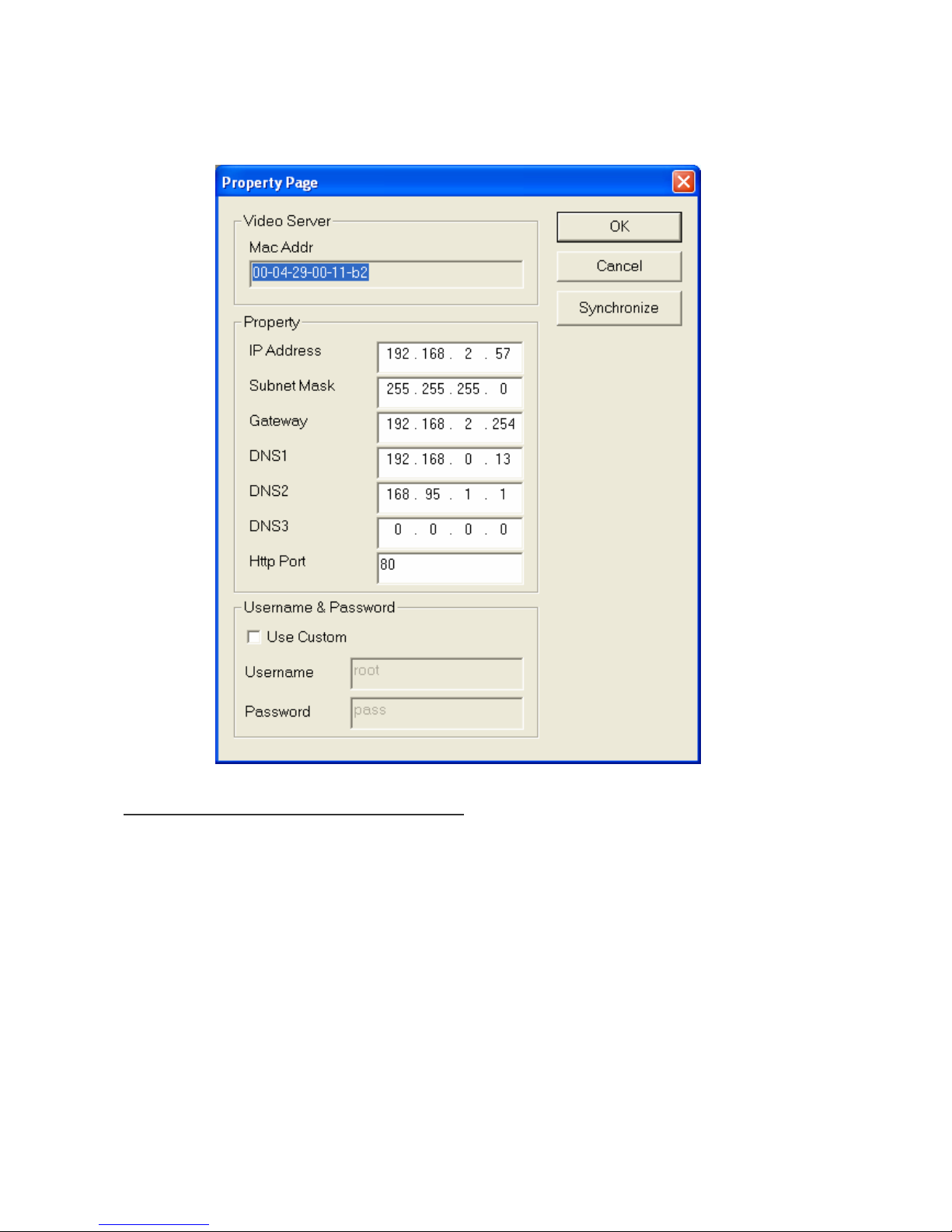
5. After filling in the properties, click [Synchronize] button to complete the configuration settings in the
remote UNC7702 while saving configuration in the PC. If click [OK] button, the configuration is only be
saved in the PC.
Open the Web-based UI of the Selected UNC7702
1. To access the Web-based UI of the selected unit, run the View > Open Web on the menu bar.
2. If the device has been configured correctly, the default Web browser will open to the home page of the
selected device.
3. If you find your browser is opened and automatically connected to the UNC7702 Home Page, it means
you’ve assigned an IP Address to the unit successfully. Now you can close the IP Installer and start to
use your UNC7702.
Page 11

10
1
Verify and Complete the Installation from Your Browser
browsing the Home Page at the first time with the Microsoft Internet Explorer
TM
, you must temporarily
security settings to perform a
When
lower your one-time-only installation of the ActiveX component onto your
workstation, as described below:
1. From the Tools menu, select [Internet Options]
2. Click the [Security] tab and then click [Custom Level] button to see your current security settings.
3. Set the security level to Low and click [OK].
4. Type the URL or IP address of your UNC7702 into the Address field.
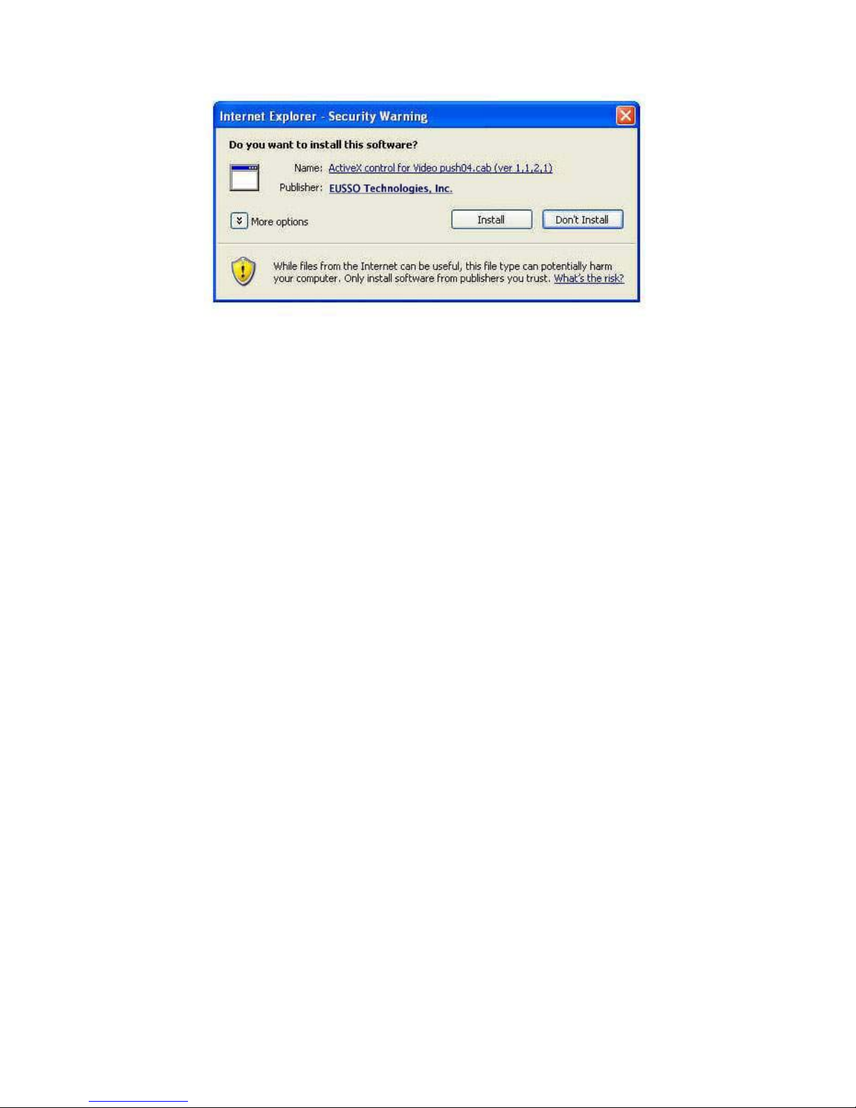
5. A dialog box will pop up asking if the ActiveX control should be installed. Click [Yes] to start the
installation.
6. Once the ActiveX installation is complete, return the security settings to their original value, as noted
above.
Page 12
11
11
Chapter 4
UI Using the Web
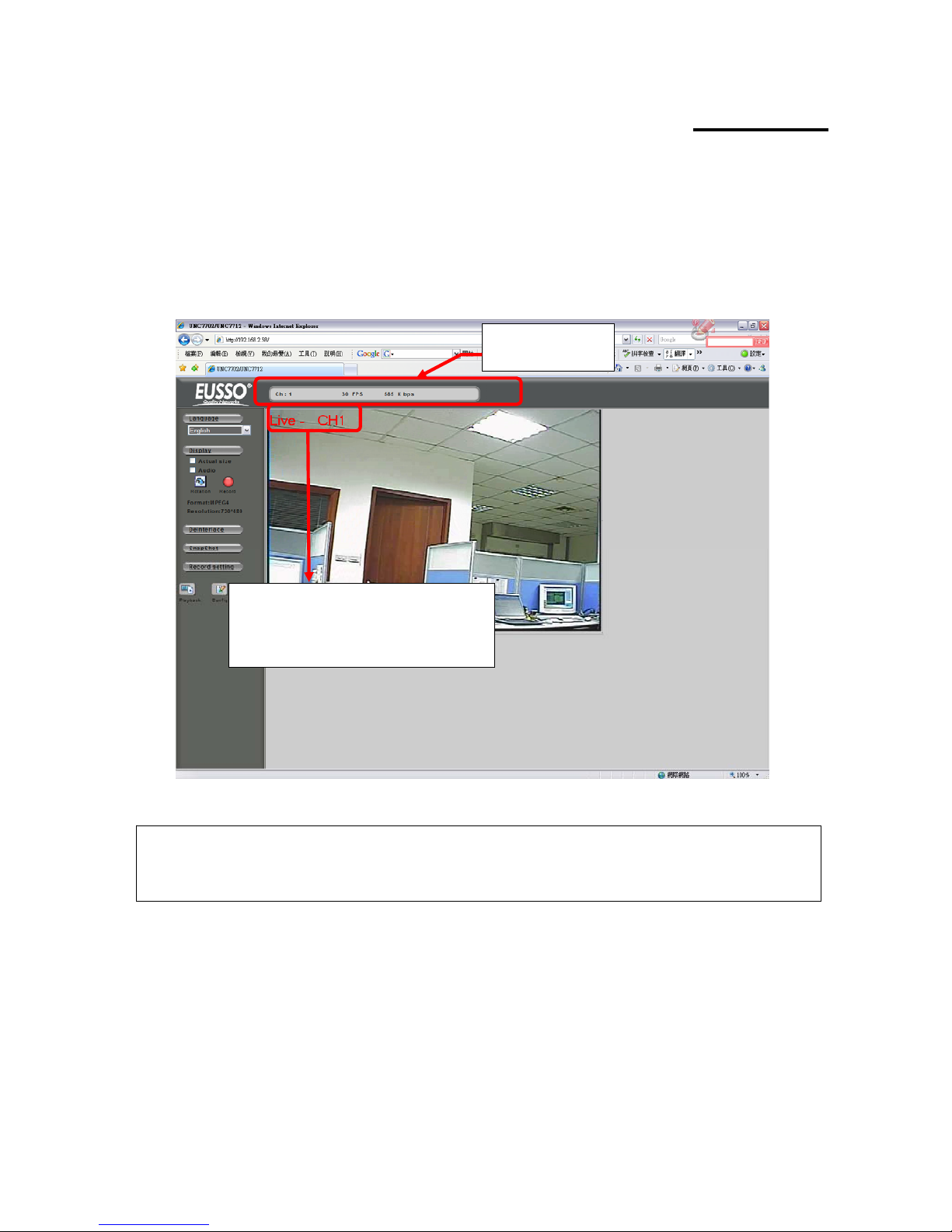
Start your Web browser and enter the URL or IP address in the Address field. The Home page of the
UNC7702 is now displayed.
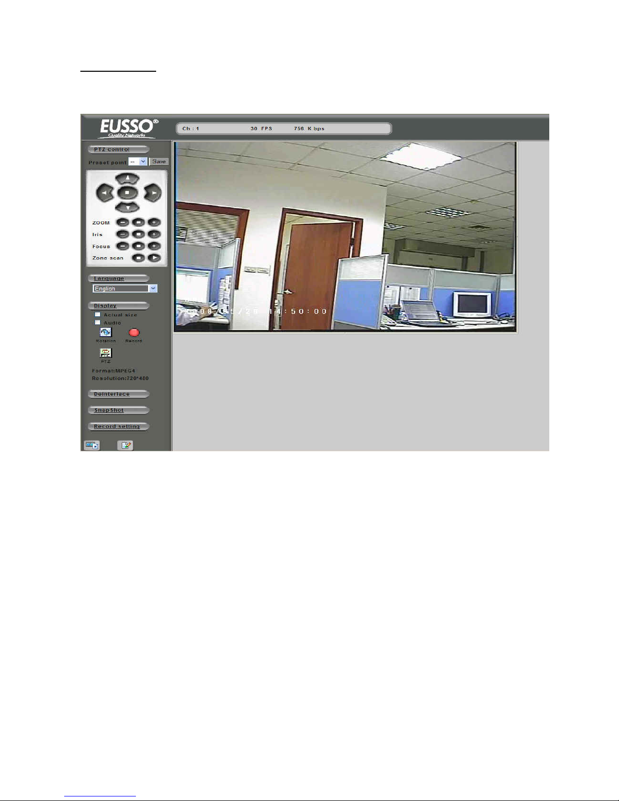
The status of the
video stream
The display of channel information can be
configured in the OSD setting, including
video status, channel number, camera title,
frame rate and transfer speed (bit rate).
Note: Please notice to install the version of XVID codec and recommends V1.1 above, it can be found in the
CD package.
Page 13
12
1
1. Live View
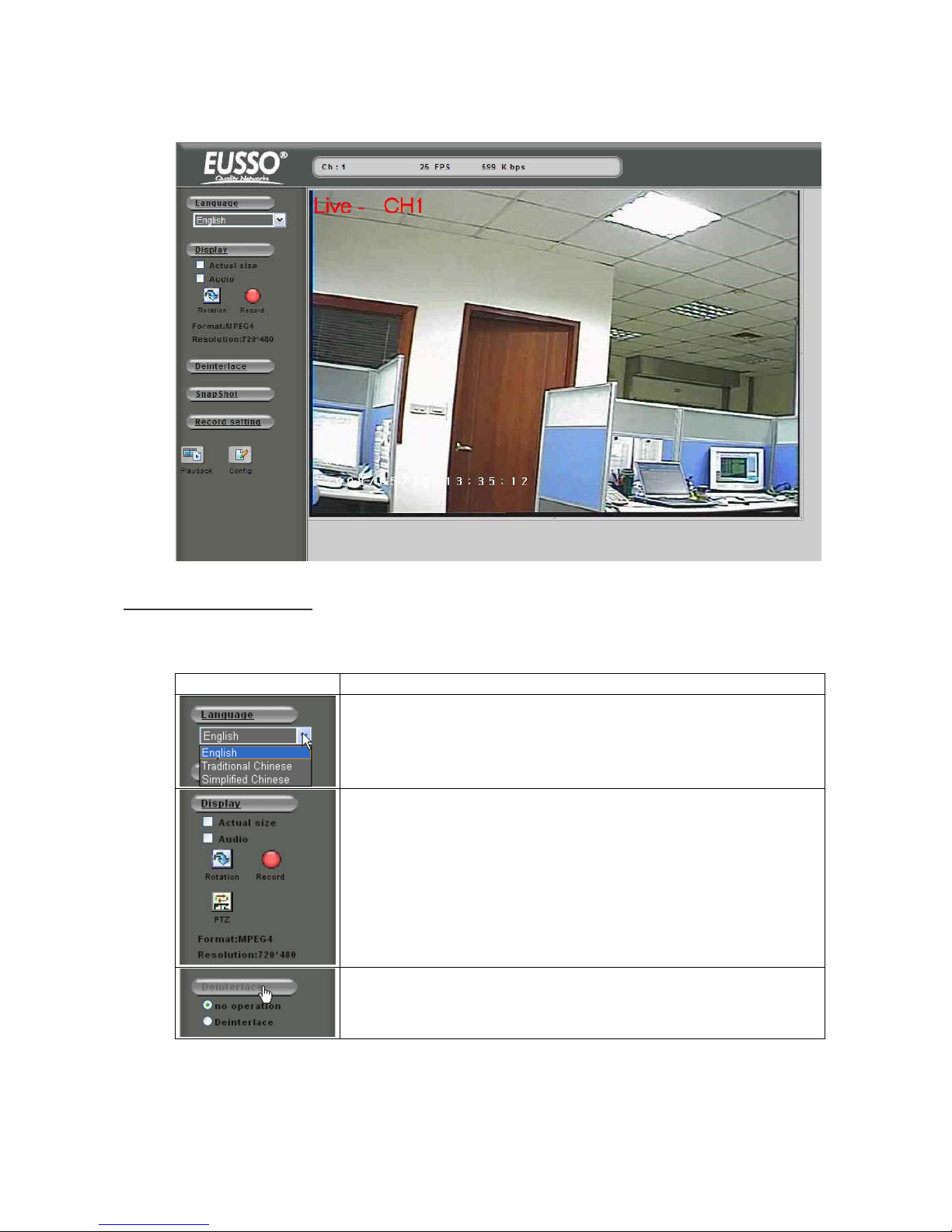
Functions in live view page
the available keys in the Live View modThe following are e:
Button Description
Select the display language for web user interface
Check “Actual Size” to display the video stream at the actual resolution
Click “Rotation” to rotate the selected video on 90 degrees clockwise direction.
Click “Record” to start/stop recording.
Click “PTZ” to show up a panel for the PTZ operation.
Check “Audio” to enable audio recording.
Click “Deinterlace” to expend the option of deinterlace.
Page 14
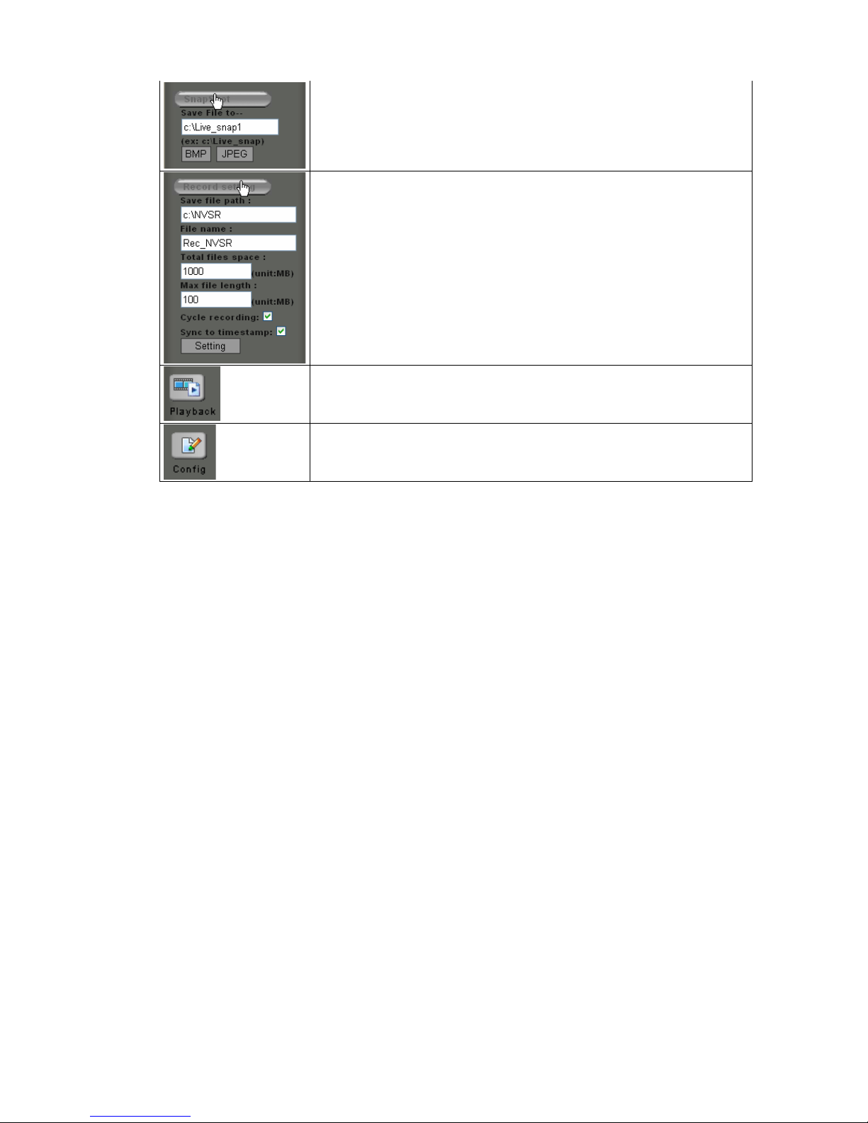
Users need to set the file path before taking the snapshot. Click on [BMP] or
[JPEG] to take an image with the bmp or jpeg file format respectively.
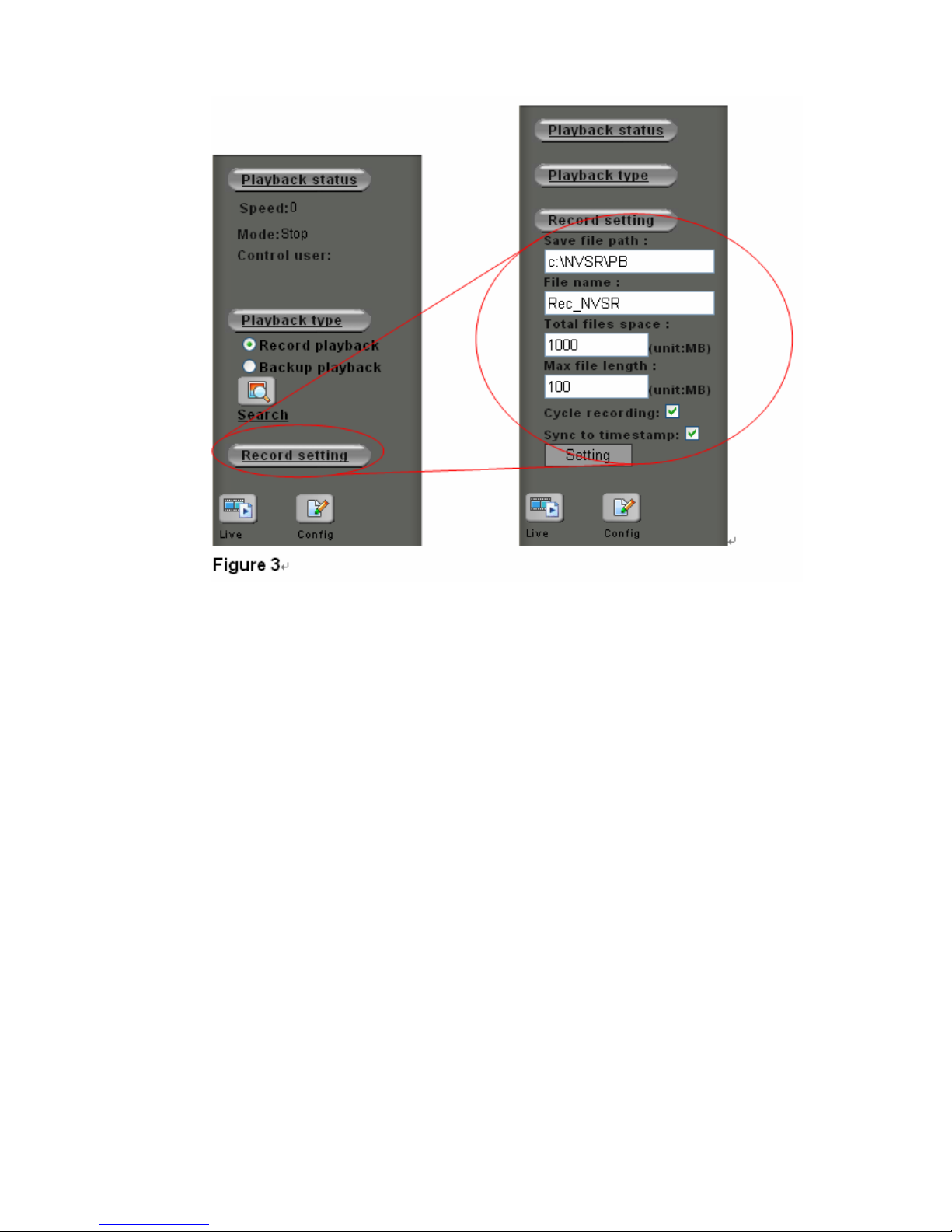
Set the recording parameters including the recording path, file name, total file
space, maximum file length, enabling/disabling cycle recording and synchronize
to timestamp. Click on “Setting” to apply the change.
Go to the Playback page for search and play back recorded video file
Note: The user that log in with user account* can’t use the Playback function
Go to the Configuration page for setup
Note: The user that log in with user account* won’t have an access to this page
UNC7702 user setting can be categorized in three groups, the Admin, operator and user. Detail
nfiguration page > System > User.
*
description can be found in Co
13
1
Page 15
14
1
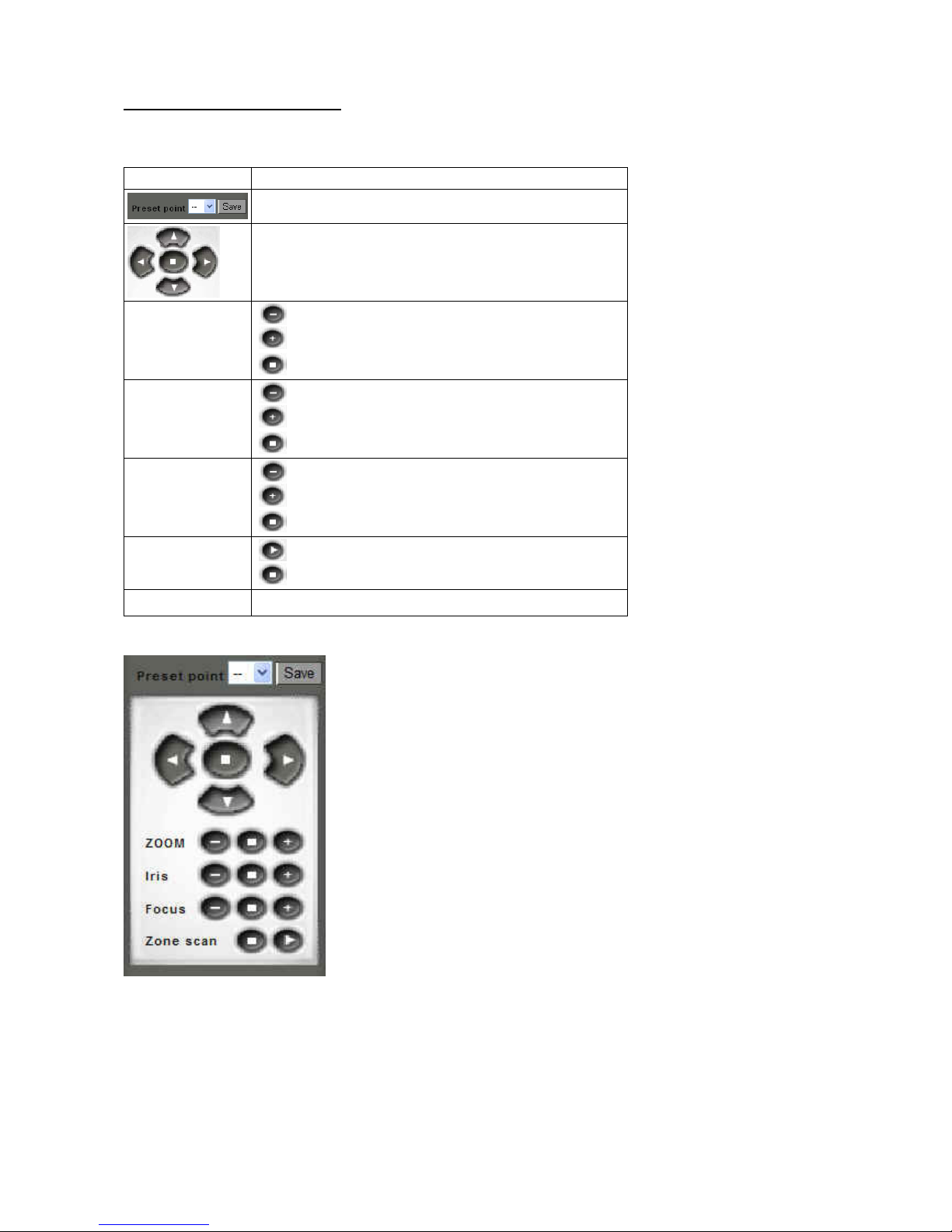
P/T/Z Control for Dome Camera
The following are the available key
Button Description
s to control the PTZ dome camera:
Select the preset point for quick view or setup
Click on the arrow buttons to move the camera to that
direction Click on the rectangle button to stop the movement
Zoom
Zoom out the video
Zoom in the video
Stop the adjustment
Iris
Open the iris and reduce glare
Open the iris and brighten the picture
Stop the adjustment
Focus
The target will become farther
The target will become nearer
Stop the adjustment
Activate the zoom pan function
Zoom scan
Stop the zoom pan function
Save Click this button will save the current data as a preset point
Page 16
2. Playback
15
1
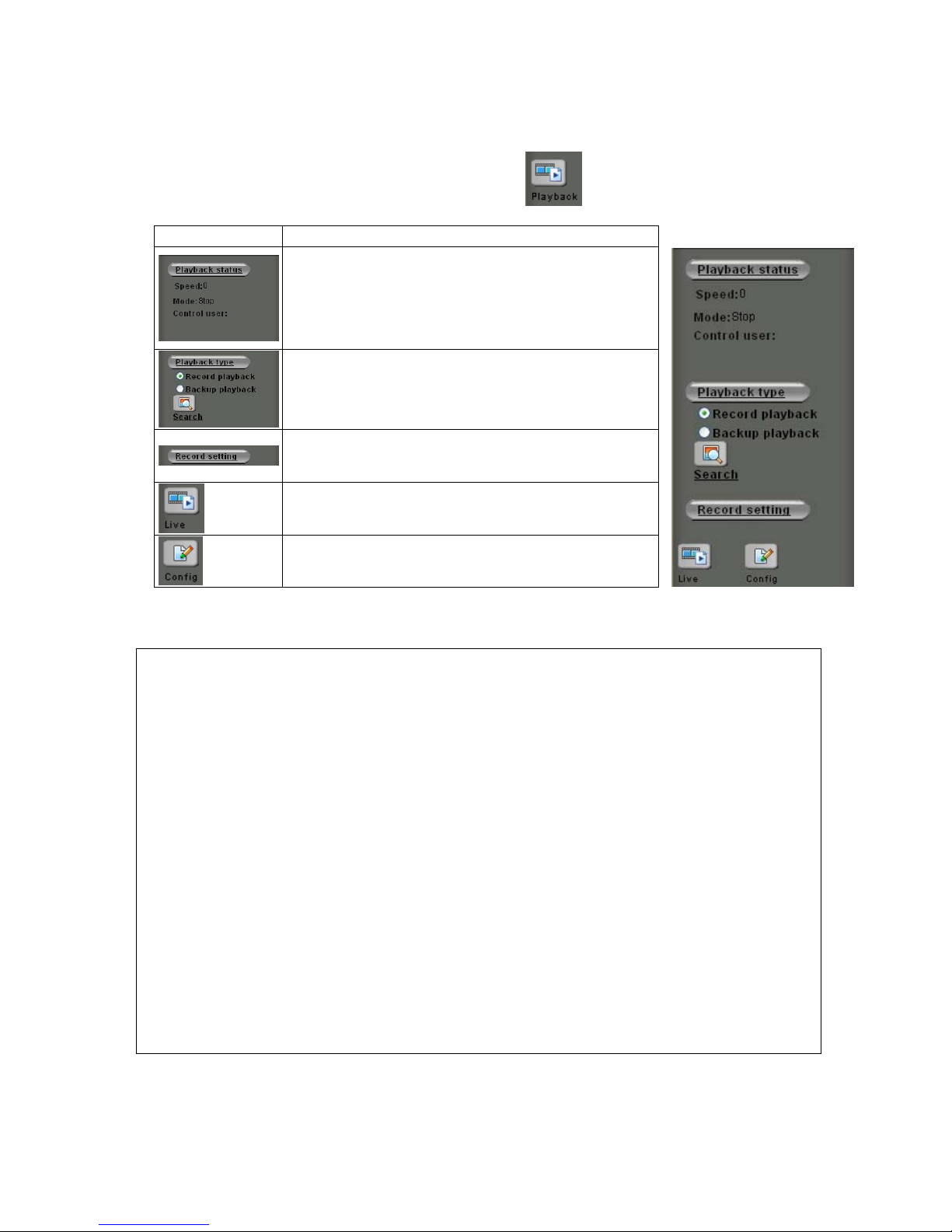
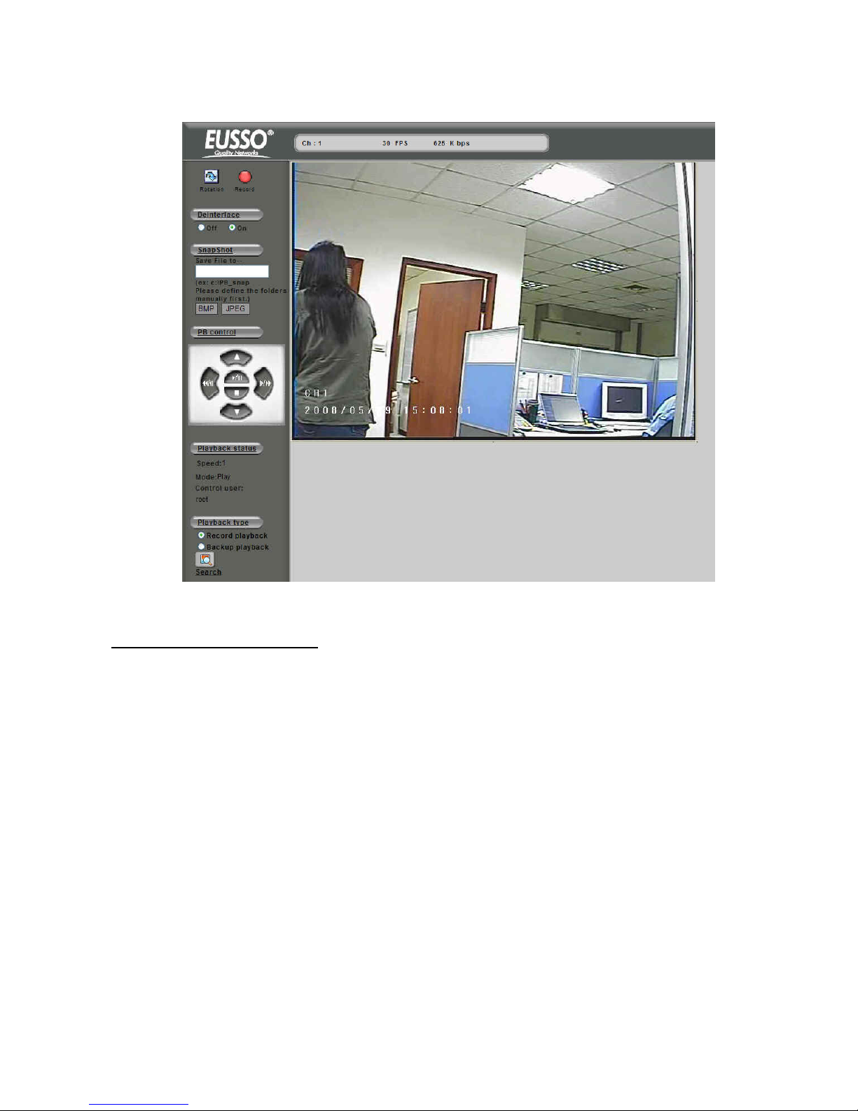
To play back the recorded file, click the button in Home pag e.
Button Description
This will be displaying playback status include the speed
of playing, playing mode and name of the controlling
user.
Select “Record HDD” or “Backup HDD” to search for the
on to open the Search recorded file. Click [Search] butt
panel, see Figure 1.
pand a setting panel for recording
the pla igure 3.
Click this button to ex
yback stream to the client PC, see F
Click this button back to the Live View mode
Go to the Configuration page for setup
Note: only 1 user can control play back streaming in a meantime. Other than the first user will be able to see
the playing only (not to control) and who is controlling.
For the first user (must at least have an operator authority) going to start playback:
1. Select the hard disk that will be searched for.
2. Click Search button to open the Date/Time panel for choosing.
3. Select by Date/Time in the calendar. To know the usage of the calendar, just move the cursor on the
button, the tips for the button will appear.
4. After select the Date/Time, click on [Begin Playback] button to playback all recorded video from the
selected time or [Event list] button to choose the recorded video files from events list, see figure 1& 2.
For other clients (even logged in as an administrator)
As one user is controlling the playback, the other clients must wait until the user stops the playback function.
During the waiting time these clients can only view the streaming of playback.
Page 17
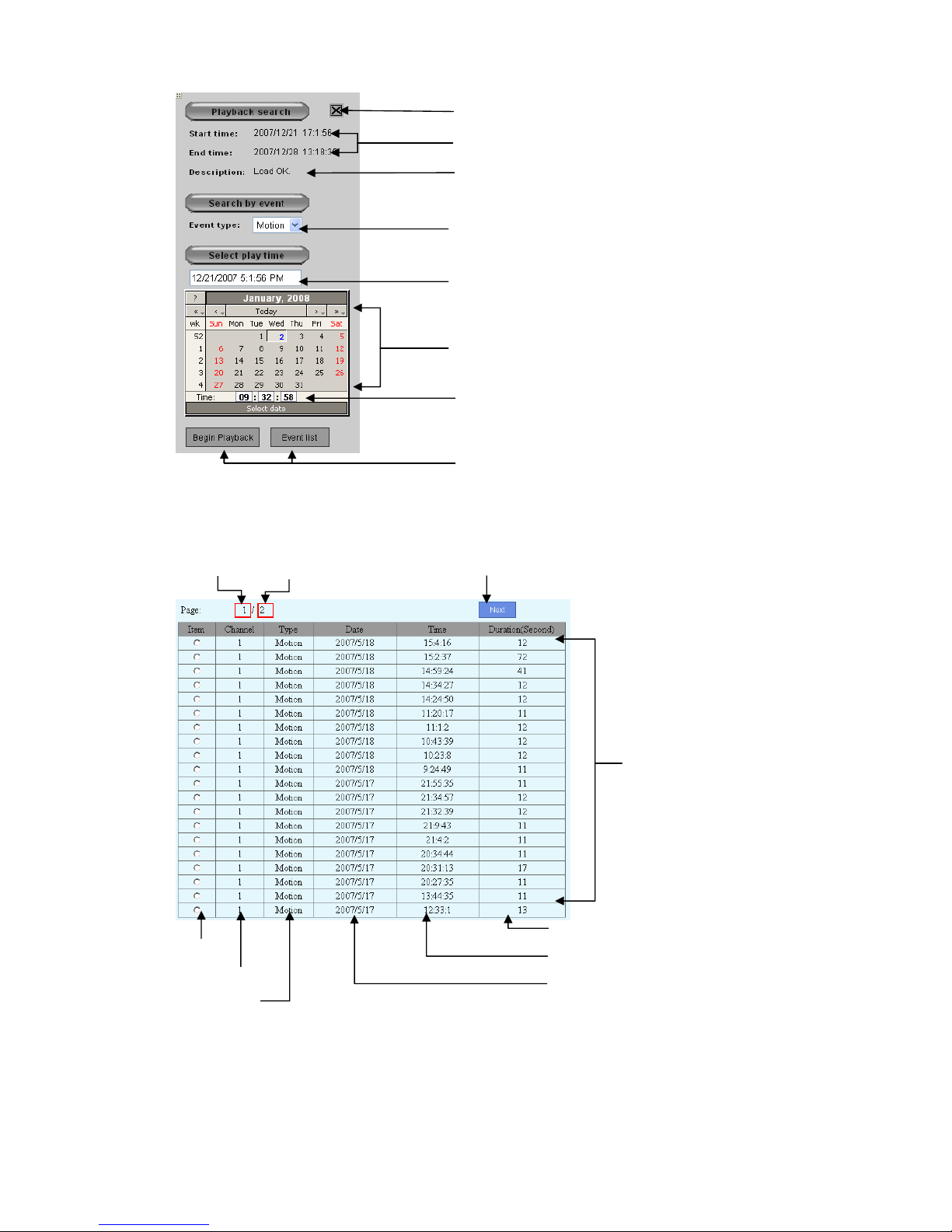
Close this panel
The start and end time of the all video recordin
g
ng you can manual input or The start time of the recordi
click calendar to play
Status of control playback
You can click this to change play time
You can click this to increase of number or press button
of “Shift” and click this to decrease of number
You can click button of “Be
click “Event List” to pla
gin Playback” to play time or
y event list
Figure 1
Current page
Total page
“Next“” button
Event List
Duration
Event Time
Event Date
Item
Channel
Event Type
Figure 2
16
1
Page 18
17
1
Playback Screen
Controller
’s View
Page 19
18
1
Other clients’ View
emote Record P layback Strea m
R
he playback stream can also be saved to a client PC while viewing. This is a handy function for that
hen a user is far away from UNC7702 but needs an actual copy of recorded video file.
. Set a path to store the video. Click on [Record setting] button. A setting panel will be expanded and sho wn.
See below figure.
T
w
1
Page 20
2. Press on the red button [Record], the playback video will be saving to the path set previously.
3. Besides save playback video, user can also snapshot an image from the video. The operation is identical
to operating in the live page.
19
1
Page 21
20
2
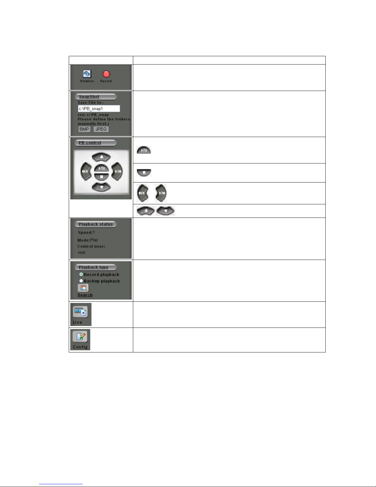
The following are the available keys to control the playback:
Button Description
Rotation: Rotate the playback images.
Record: Record the playback video while viewing.
Same operation as in live page. Snapshot the playback video.
Play / Pause / Resume the playback
Back to 1X speed for playback
Stop the playback and exit the Playback function
Fast forward / Rewind the playback. 1X ~ 32X speeds
selectable.
Playback in slow motion. After pause, select the speed from
1X ~ 1/32X.
Show the status of playback.
Click [Search] button to search and play back another time of recorded file
Click this button back to the Live View mode
Go to the Configuration page for setup
Page 22
21
2
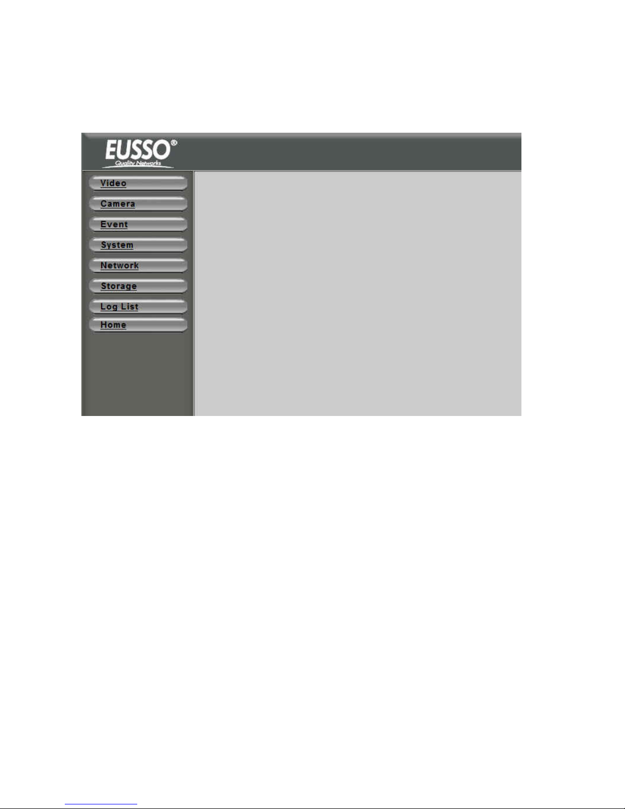
ation page
Click “Config” icon to open the Co
3. Configur
nfigure Page
.
- Video: Set up the resolution and quality for recording and live view, and the schedule recording
- Camera: Setup video parameters, PTZ settings for cameras
- Event: Setup for event trigger
- System: Setup for system including date/time, user, COM port and commands etc.
- Network: Setup for network
- Storage: Setup for recording
- Log List: Display the log
- Home: Back to the Home Page
The detail descrip s / configurations are in the following chapter.
storage and schedule.
tion
Page 23
22
2
Chapter 5
eb UI
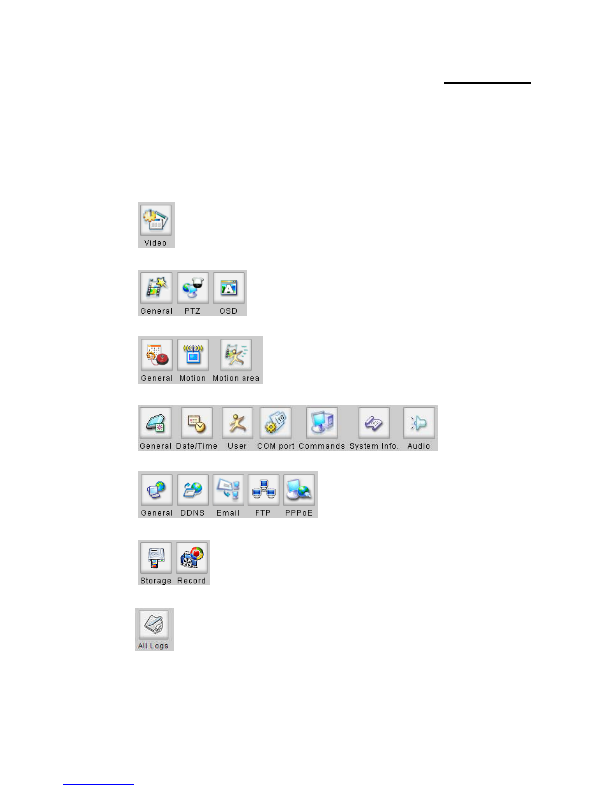
1. Sub items
Video:
Configure the Settings with W
Camera:
Event:
System:
Network:
Storage:
Log List:
Page 24
23
2
2. Video Setup (Available for Administrator only)
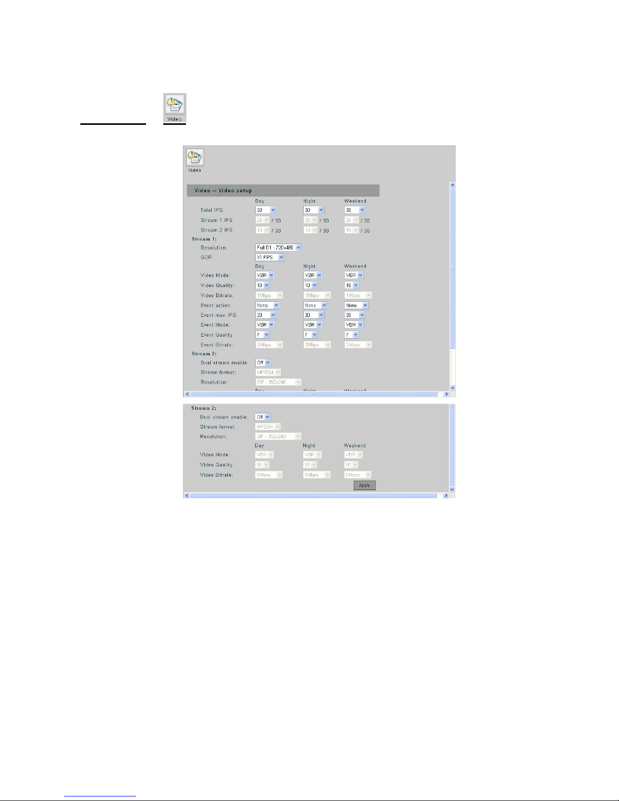
Video Setup
Set Total IPS in the daytime, nighttime and on weekends, up to 30 for each time period. When
nabled, the IPS for stream 1 and 2 can be configured.
Stream 1 IPS: Set IPS for Stream 1 out of 30.
Stream 2 IPS: Set IPS for Stream 2 out of a number the rest IPS after occupied by Stream 1.
- Resolution: Streaming / Recording resolution can be selected from 352X240 (SIF), 720X240
nd (Full D1).
size
- Video Mode: Choose video encoding mode between VBR (Variable Bit Rate) and CBR
(Constant Bit Rate)
- Video Quality: Video quality is divided into levels(1-31), a better video quality is presented in
Tot al IPS:
stream 2 is e
Stream 1:
(Half D1) a 720X480
- GOP: Set the GOP
Page 25

24
2
trate can be selected among
64 Kbps, 128 Kbps, 256 Kbps, 512 Kbps, 768 Kbp s, 1 Mbp s, 1.5 Mbps, 2 Mbps, 3 Mbps and 4
- Event action: Choose Motion (motion detection), Sensor (sensor triggering) or Both (enable
both types) for the event action. The configurations hereafter titled with “Event” will take effects
when any event action is selected; no effects when None is selected.
- Event max IPS: Select the maximum IPS that will be applied when there is an event.
- Event Mode: Choose encoding mode (VBR/CBR) when there is an event.
- Event Quality: Choose image quality when there is an event.
- Event Bitrate: Select the video bitrate when there is an event. The CBR must be selected for
event mode to enable this selection.
Stream 2:
- Dual stream enable: Set the second stream On/Off.
- Stream format: The stream format can be set to “MJPEG” or “MPEG4”.
- Resolution: Streaming resolution can be selected from 352X240 (SIF), 720X240 (Half D1)
and 720X480 (Full D1).
- Video Mode: Choose VBR or CBR for stream 2 video encoding mode.
- Video Quality: Choose stream 2 video quality from 31 levels (1~31).
- Video Bitrate: Choose Stream 2 video bitrate when video mode is CBR.
choosing lower number..
- Video Bitrate: When choosing CBR for the video mode, video bi
Mbps.
Page 26
25
2
3. Camera
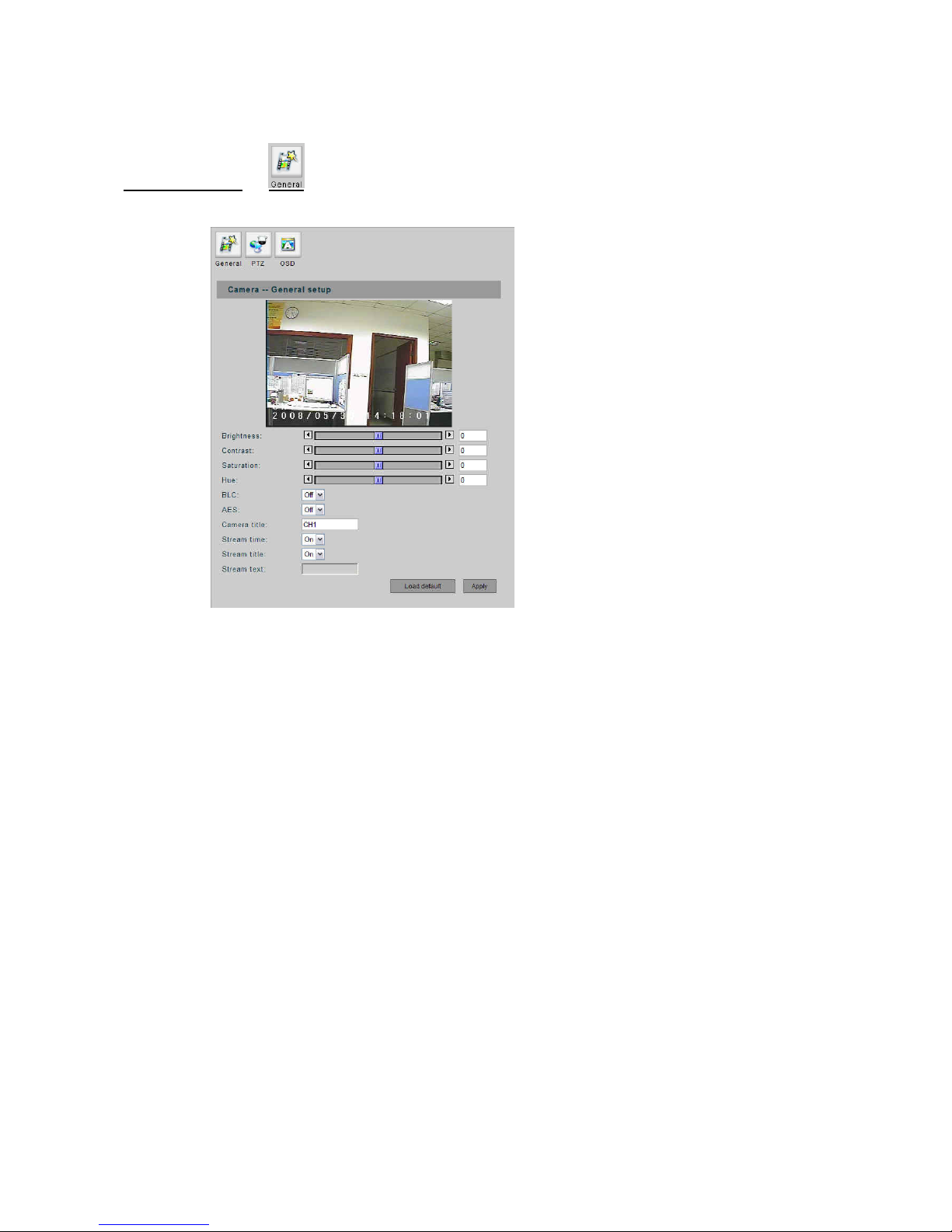
General Setup
Setup
Brightness: Adjust the brightness for each channel from -100 to +100.
Contrast: Adjust the contrast for each channel from -100 to +100.
- Saturation: Adjust the saturation for each channel from -100 to +100.
- HUE: Adjust the hue for each channel from -100 to +100.
- BLC: Enable/disable BLC (Back Light Compensation) function.
- AES: Enable/disable AES (Auto Electronic shutter) function.
Note: The BLC nd AES functions will not appear in this page when connecting to a video server
(show only in ca ra setting page)
- Camera Title: Input the camera title to shown on the screen.
- Stream time: on/off the time displaying on the live video.
- Stream title: on/off the title displaying on the live video.
- Stream text: when stream title is set off, this filed can be input some texts for displaying on the
video.
- Load Default: Restore to the default settings.
- Apply: Confirm the settings.
-
-
a
me
Page 27
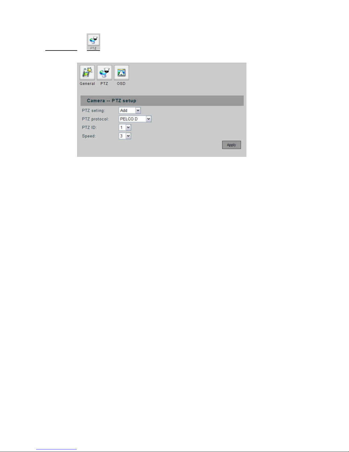
PTZ Setup
- PTZ Setting:
Remove: No dome camera is connected to this channel.
Add: A dome camera is connected to this channel.
- PTZ Protocol: Various protocols can be selected, including PELCO P, PELCO D, LI-LIN and
Dynacolor.
- PTZ ID: The ID number must match the ID address set by the dome camera.
Speed: Select the control speed from 1 ~ 10.
-
- Apply: Confirm the settings.
26
2
Page 28
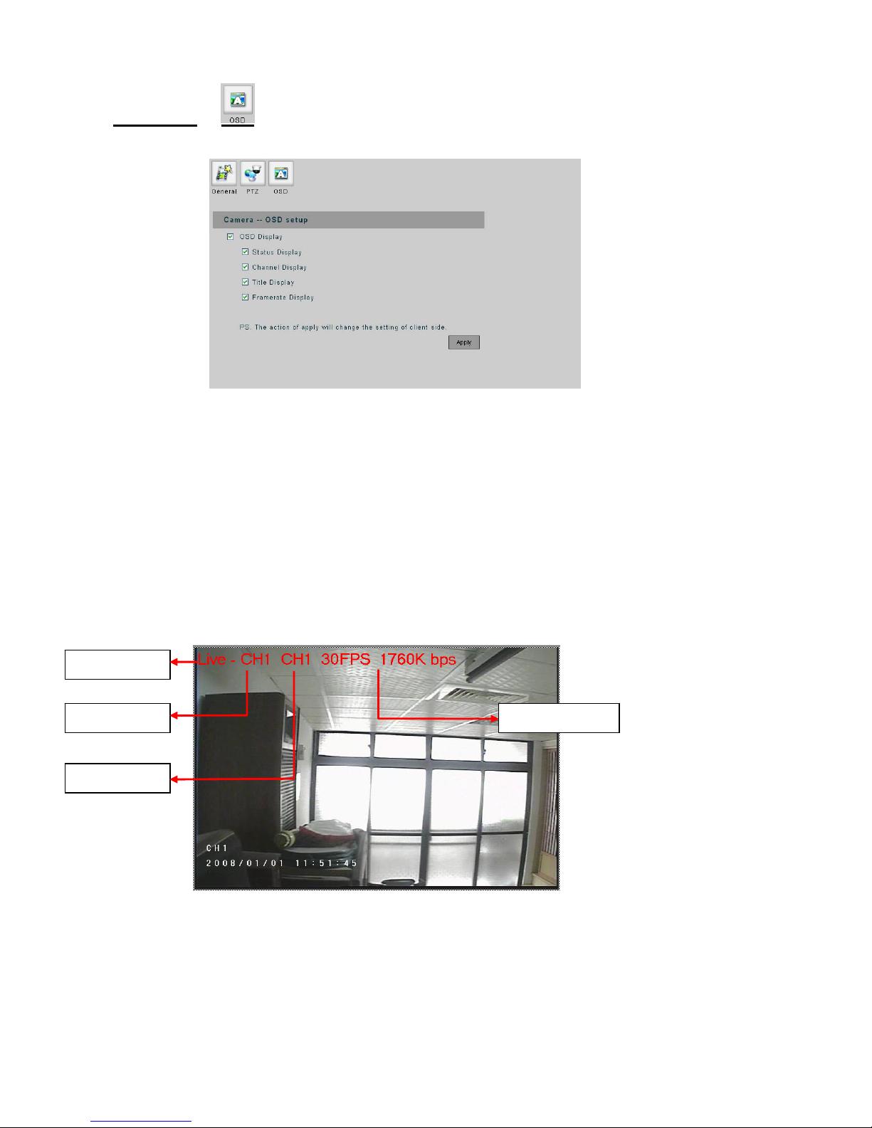
OSD Setup
- OSD Display: Check the check box to display the following messages on the video of each
on’t affect the other PC and the video device.
- splay: Display the channel number of each channel.
bit rate of each channel.
channel.
Note: The settings work with this client PC only; it w
- Status Display: Display the video status (Live or Playback video).
Channel Di
- Title Display: Display the camera title of each channel.
- Frame rate Display: Display the frame rate and
- Apply: Confirm the settings.
Frame rate Display Channe isplay l D
Title Display
Status Display
27
2
Page 29
28
2
p
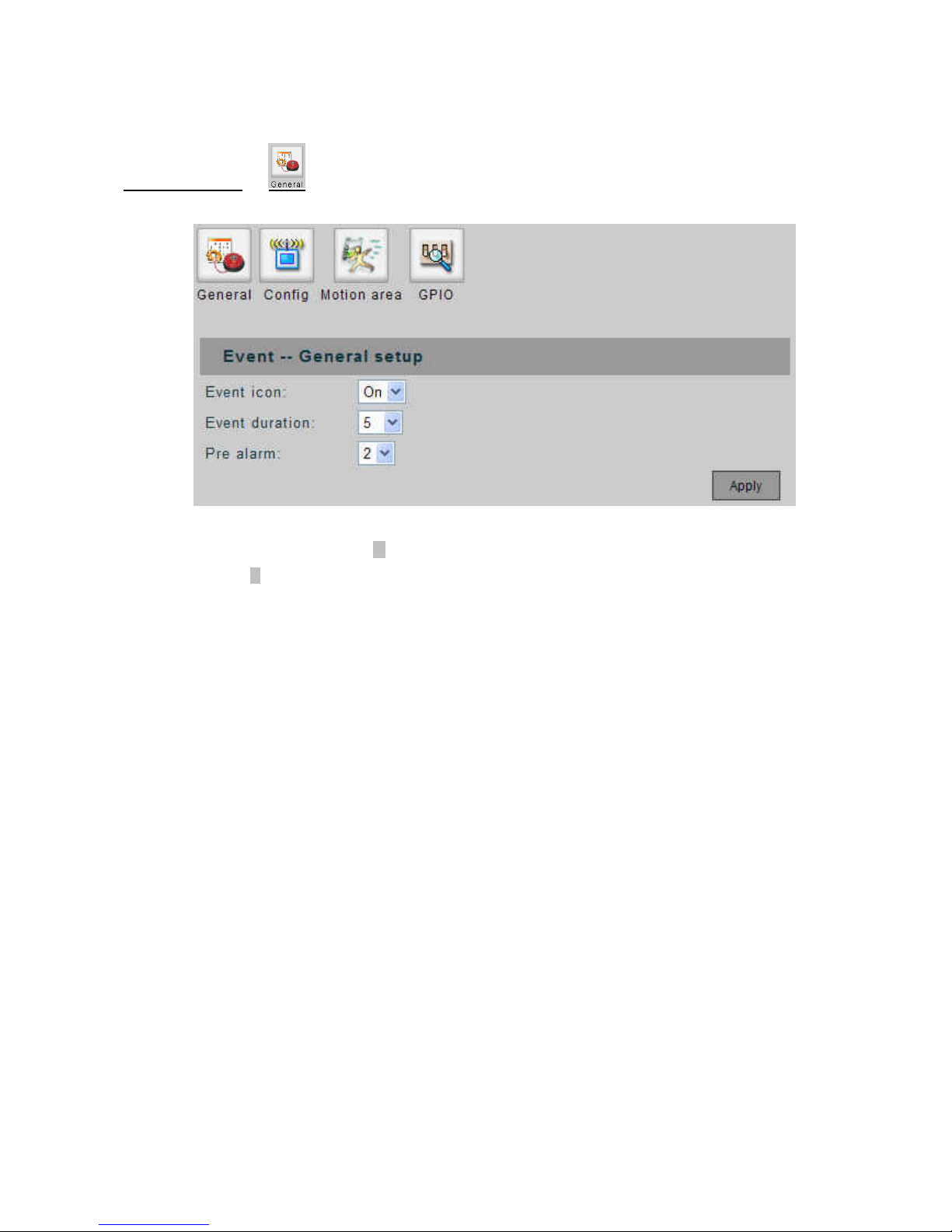
General Setup
4. Event Setu
- Event Icon: When set to “ON”, an M icon will be displayed on the screen when the Motion Detection
is triggered; an S icon will be displayed on the screen when the Alarm IN is triggered. The event icon
’t be displayed on the web UI.
way . Available selections
econds.
Pre Alarm: When an event is triggered, a video clip will be sent with Email or saved to FTP site. You
e event is triggered. The
it is in second.
- Apply: Confirm the settings.
will be displayed on the video output of UNC7702; it won
- Event Duration: Set the duration time for recording after the event goes a
are 5, 10, 15, 20, 25 and 30 s
-
can adjust this option to determine the beginning time of video clip before th
un
Page 30
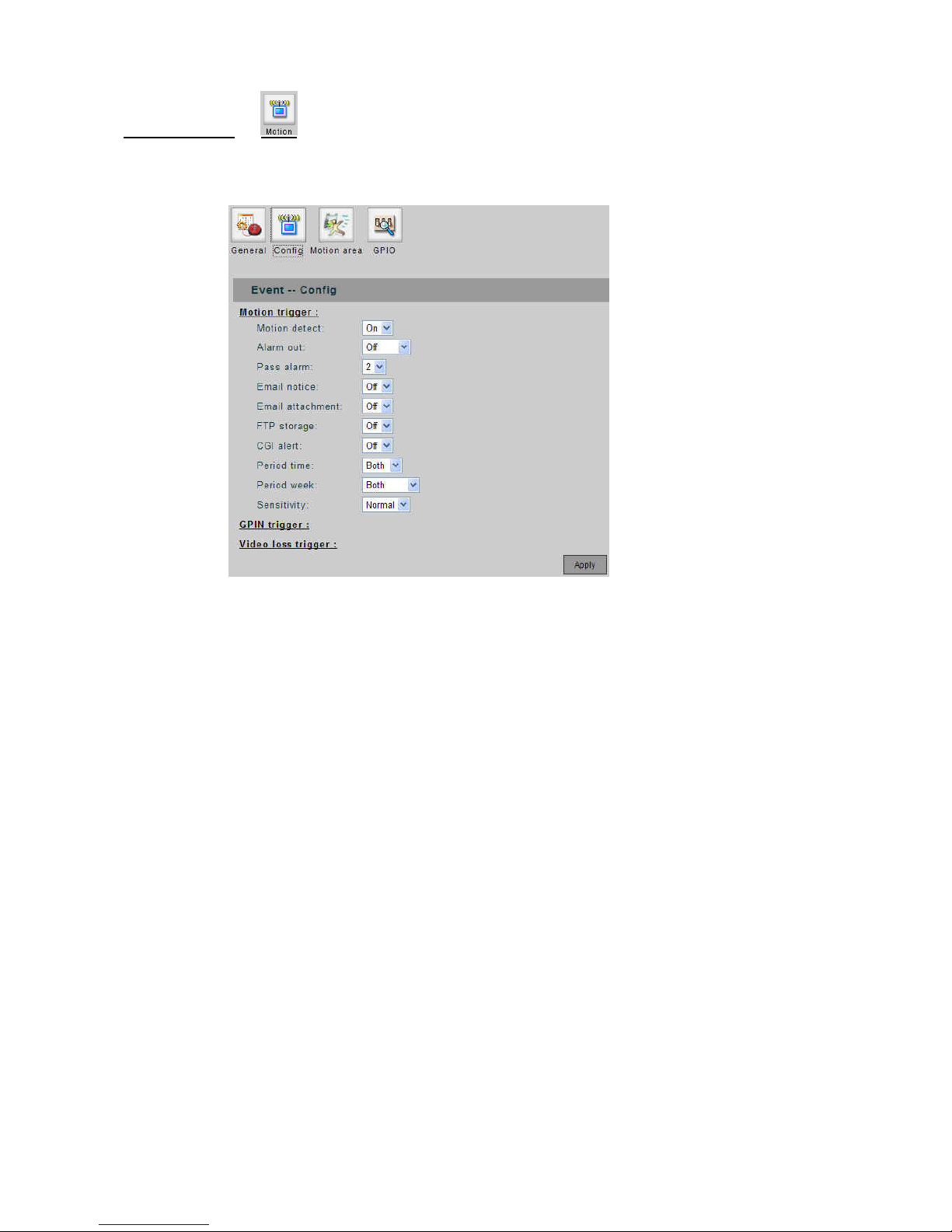
Motion Setup
Motion config:
-
nd.
ble the Email notice when motion detection is triggered.
Email Attachment: Set whether attach the video clip with the Email notice when motion detection is
triggered.
FTP Storage: Enable or disable whether send the video clip to FTP site when motion detection is
triggered.
CGI Alert: Enable or disable to send CGI alert when motion detection is triggered.
Period Time / Week: Select the period that the motion detection should be activated. Day、 night、
weekday、 weekend or all the time.
Sensitivity: Set the sensitivity of motion detection.
Define parameters for actions responding to detected motion.
- Motion Detect: Set the Motion Detect feature for each channel to “ON” or “OFF”.
Pass Alarm: Adjust this option to determ ine the ending time of video clip af ter th e event goes away.
The unit is in seco
- Email Notice: Enable or disa
-
-
-
-
-
29
2
Page 31
30
3
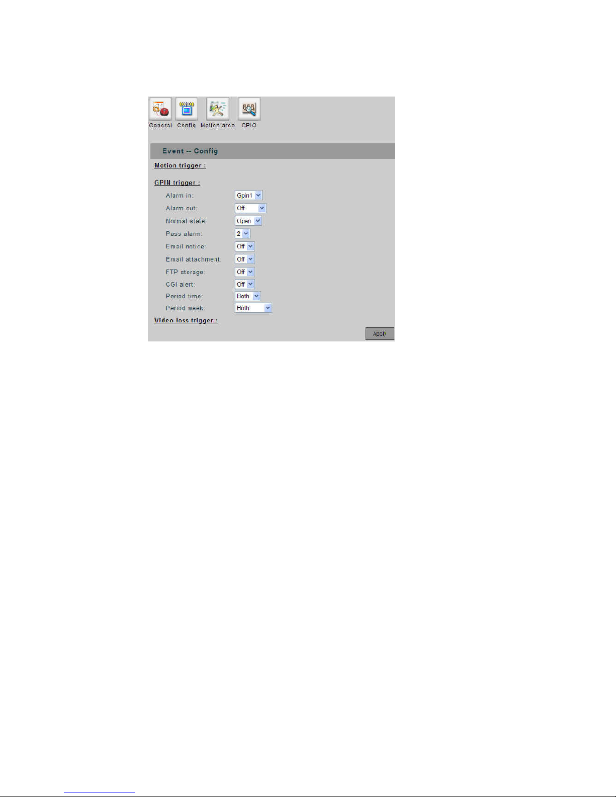
Sensor config:
Apply the sensor relays as trigger. Define the actions/parameters responding to sensed event.
event triggering.
Normal state: set the relays’ initial st atus.
- nd email with attached video file.
- e / week: select the period of time/day in a week that the sensor will be activated.
- Alarm in: select one of the four GPINs as a sensor for the
-
- Pass alarm: as described in motion config.
- Email notice: send email responding to a sensed event
Email attachment: se
- FTP storage: send video file to FTP server responding to a sensed event.
- CGI alert: enable the CGI alert responding to a sensed event.
Period tim
Page 32
31
3
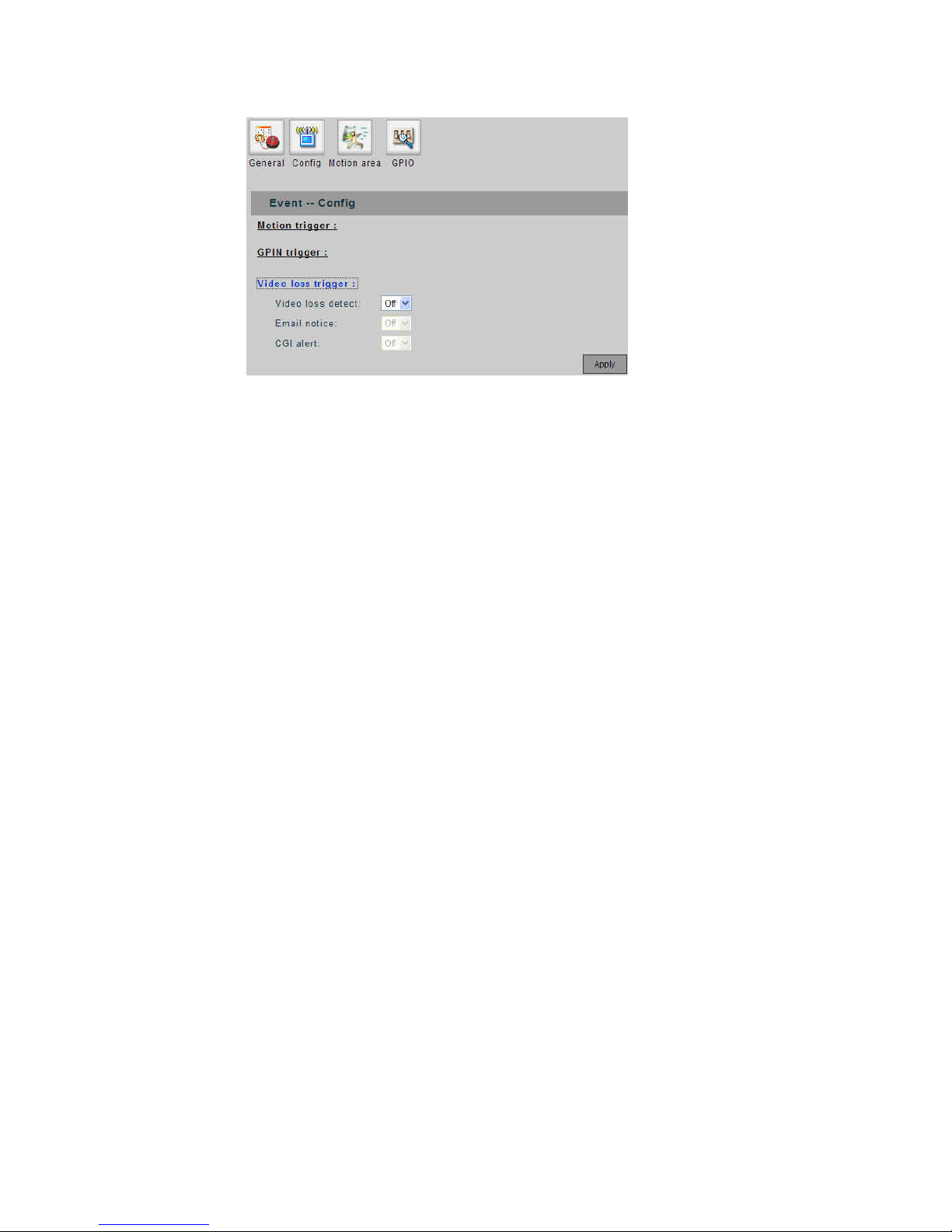
g: Video loss confi
Set actions responding to the event that video is missing, such as line has been cut or camera has been
crashed.
- Video loss detect: on/off this function.
- Email notice: as described in previous two items.
CGI alert: as described in previous two items. -
Page 33
32
3
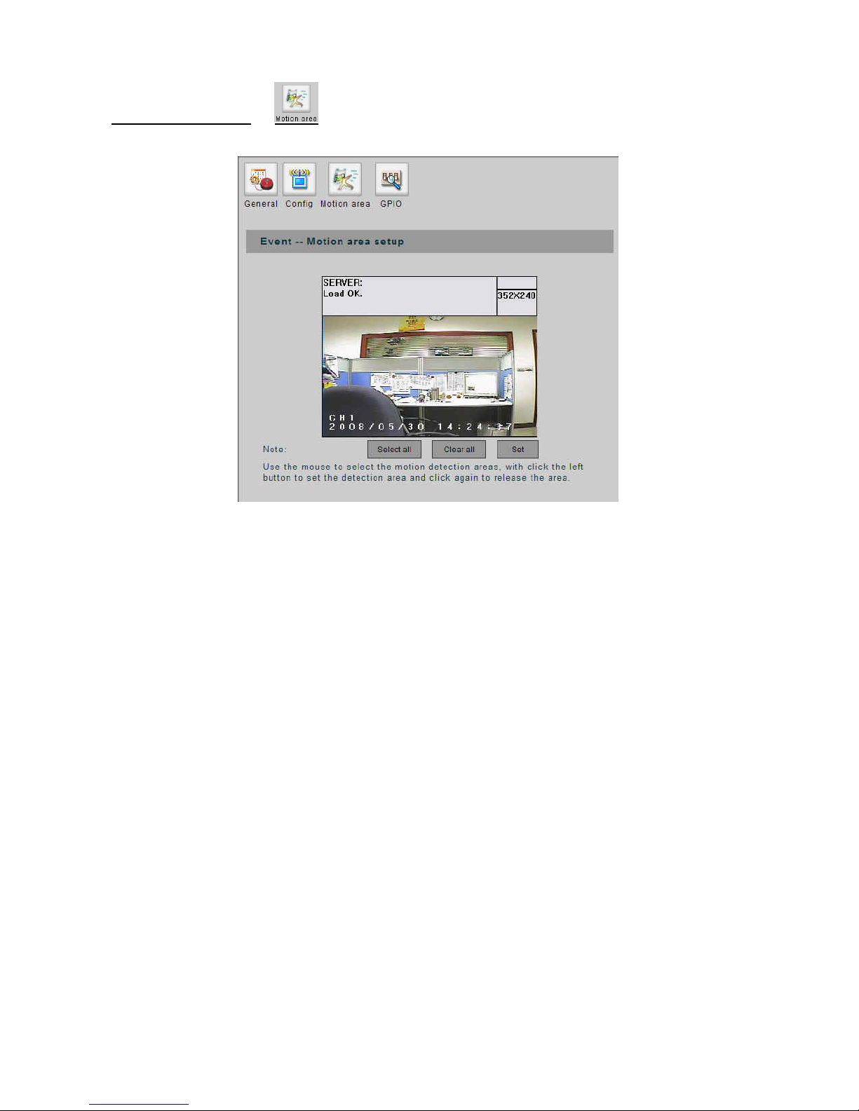
Motion Area Setup
- Select All: Clear all areas for motion detection.
Clear All: Select all areas for motion detection.
Set: Confirm the settings.
ove mouse to point the area, left-click mouse to set the area for motion detection; lef t-click the selected
rea again will clear the area for detection.
-
-
M
a
Page 34
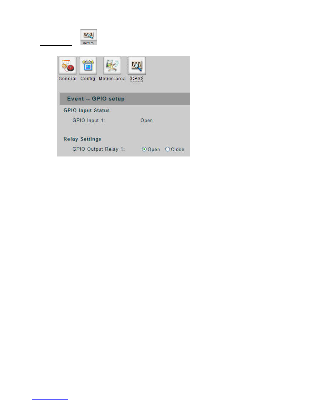
GPIO Setup
- Displays the GPIO input/output statues. Can manually adjust the statues of GPIO output by clicking
on the check box.
33
3
Page 35
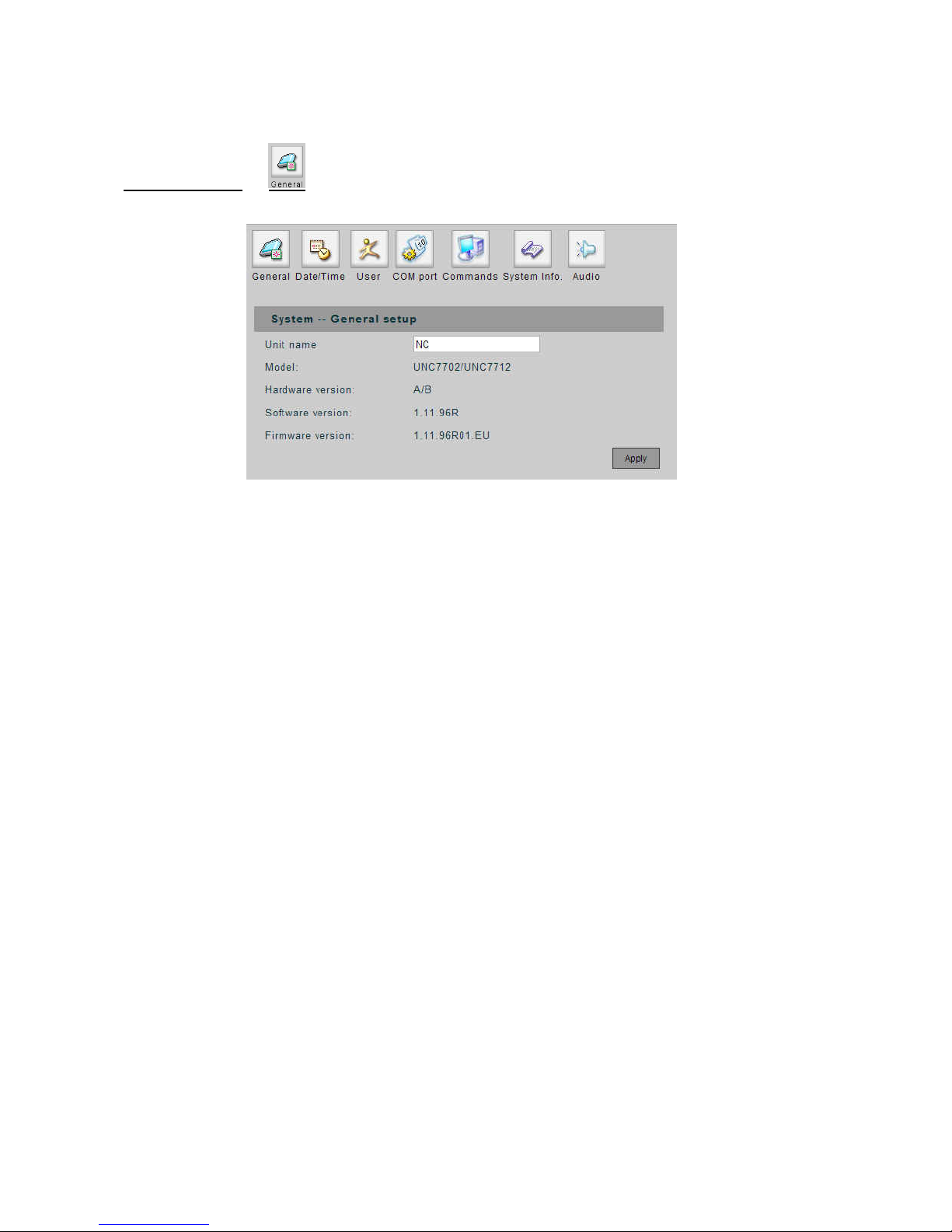
5. System Setup
34
3
General Setup
- Unit Name: Assign a name for the device.
Model: The model - name of the device.
Hardware Version: Th e version of the hardware.
Software Version: The version of the software.
Firmware Version: The versio n of the firmware.
Apply: Confirm the settings.
-
-
-
-
Page 36
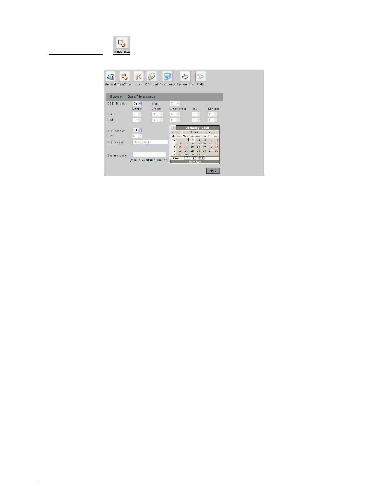
Date/Time Setup
et the year, date and time for the device.
ing time, set the item to “ON”.
rward from the standard time for daylight saving time.
aving.
ing.
a NTP server, this will synchro nize the time with
GMT: Set the time zone.
NTP Server: Input the IP address of the NTP server.
Set Manually: Set the time manually. You can select the time from the calendar.
Apply: Confirm the settings.
S
- DST Enable: If your region use daylight sav
- Bias: Set the amount of time to move fo
- Start: Set the beginning date/time of the daylight s
- End: Set the ending date/time of the daylight sav
- NTP Enable: Set to “ON” if you wish to connect to
the time server via network.
-
-
-
-
35
3
Page 37
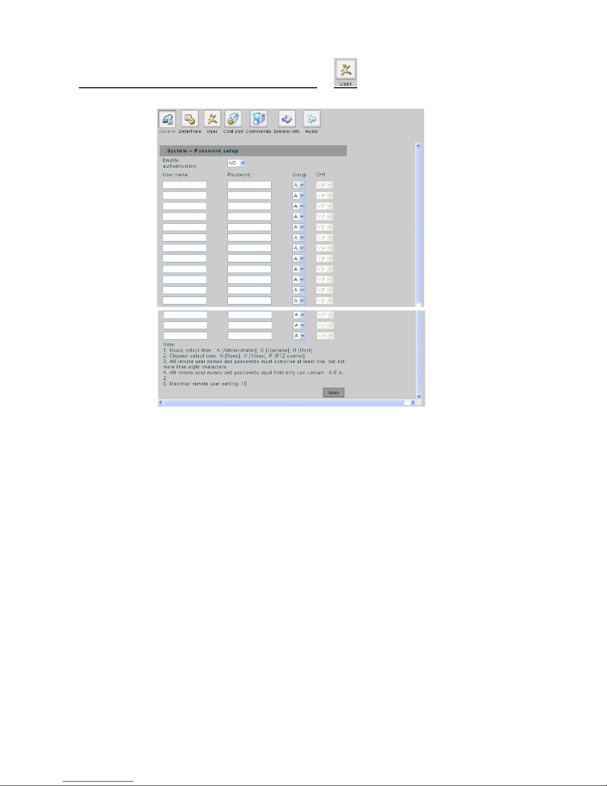
36
3
y)User Setup (Available for Administrator onl
elect “YES” to enable the password authentication.
ded for accessing this device. The account
bination of 0-9
Group: A user should also be configured into a group (Administrator, Operator, User) for different
level of authority , in addition, the right s on access to the device (the capabilities of viewing live video,
controlling PTZ cameras or none/both of them) if it is not set to the administrator group.
Apply: Confirm the settings.
- Enable Authentication: S
- User name / Password: Up to 15 accounts can be ad
name and password can be flexible (but restricted in 8 characters long of any com
and A-Z).
-
-
Page 38
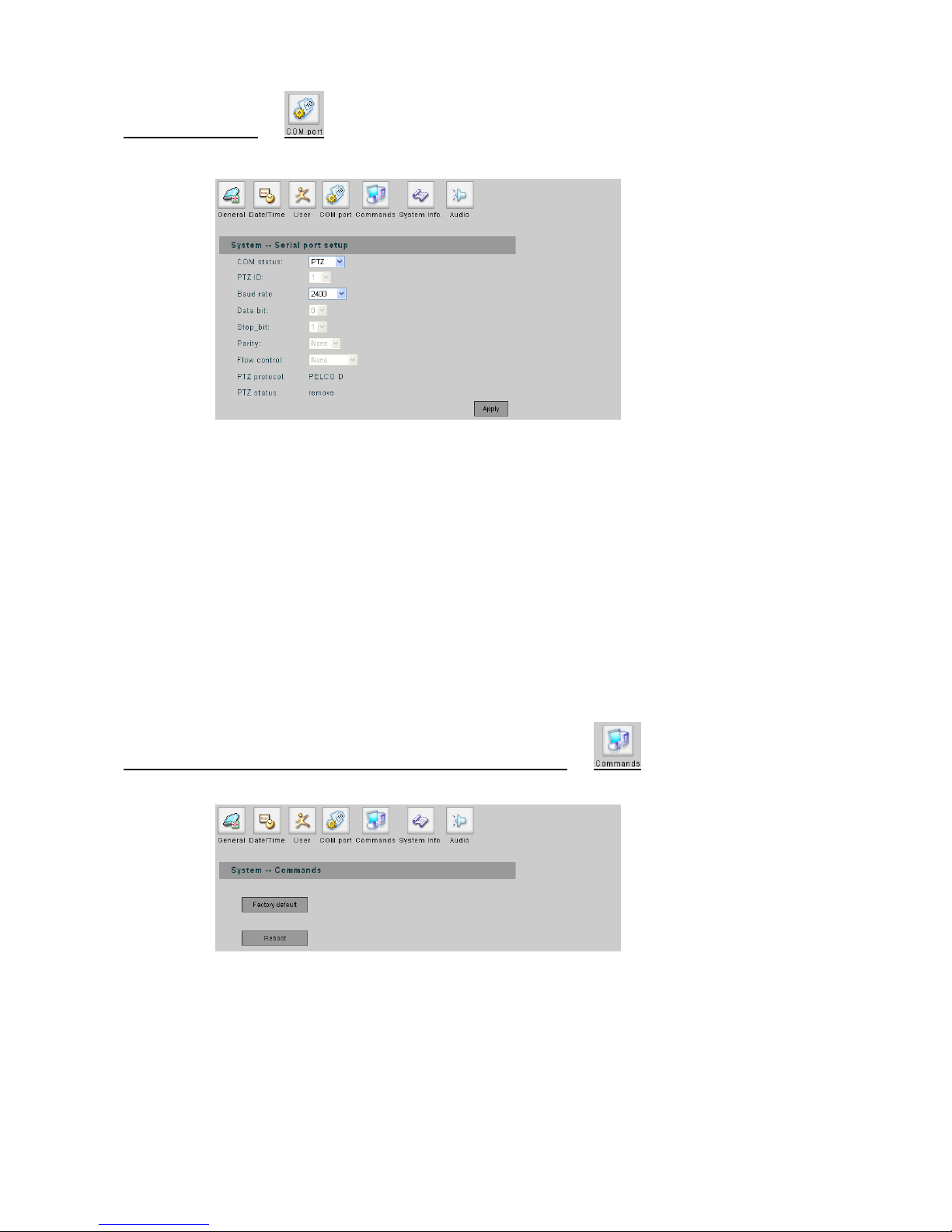
COM Port Setup
- COM Status: Set COM port for PTZ, RS-232 or RS-485.
- PTZ ID: The number must match the ID address set by the dome camera.
- Baud Rate: Set the value if necessary.
- Data Bit: Set the value if necessary.
- Stop Bit: Set the value if necessary.
- Parity: Set the value if necessary.
- Flow Cont et the value if necessary.
PTZ Protocol / Status: Display the PTZ protocol and the st atus of the connected dome camera.
System Commands (Available for Administrator only)
rol: S
-
- Apply: Confirm the settings.
- Factory Default: Restore the settings to the factory defaults.
Reboot: Restart the device. -
37
3
Page 39
38
3
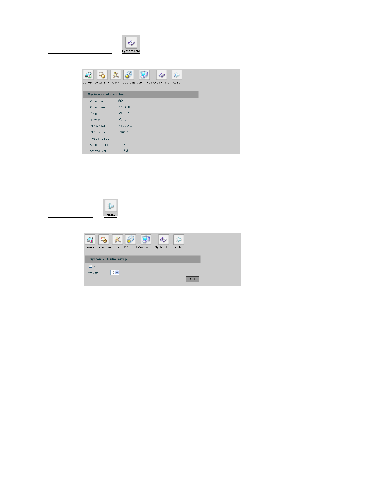
System Information
Display the information of this device. Information includes video port, resolution video type, bit rate,
X version.
-
PTZ model/status, motion status, sensor status and Active
System Audio
- System audio enable and adjustment; Mute check box to silencing, V foolume r the sound volume
adjustment.
Page 40
6. Network Setup
39
3
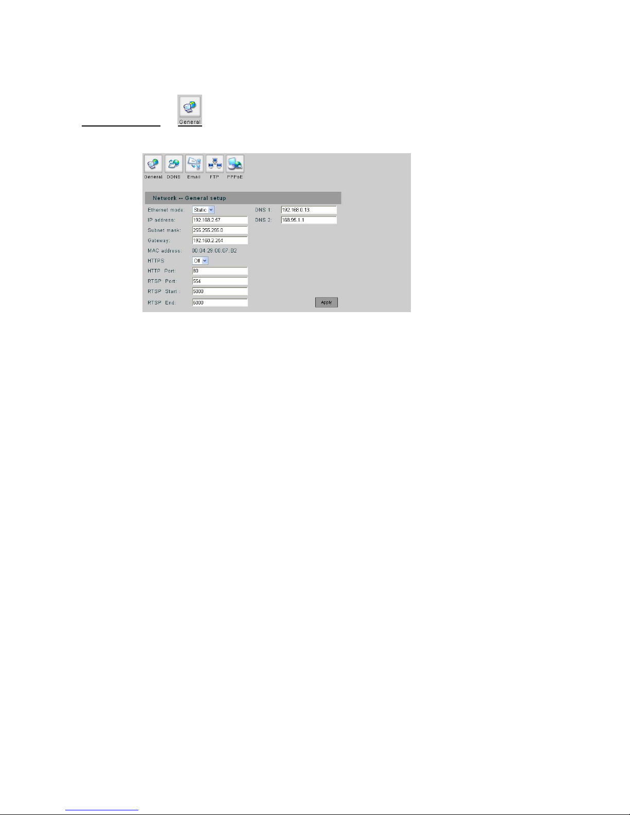
General Setup
- Ethernet Mode: If using static IP, set to “Static” and then setup the following settings. If there is a DHCP
ork, HCP”, the device will get the following settings from the server
automatically.
- IP Address: Set the IP address of the device.
- Subnet Mask: Set the subnet mask.
- Gateway: Set the IP address of the gateway on the network.
- MAC Address: Shows the MAC address of the device.
- HTTPS: on/off the HTTPS option.
- HTTP Port: Change the port if necessary.
- nge the port if necessary. Default port is recommended.
RTSP End: Change the port if necessary. Default port is recommended.
DNS1 / DNS2: Set the IP address of the DNS server .
Apply: Confirm the settings.
server on the netw set to “D
- RTSP Port: Change the port if necessary. Default port is recommended.
RTSP Start: Cha
-
-
-
Page 41
40
4
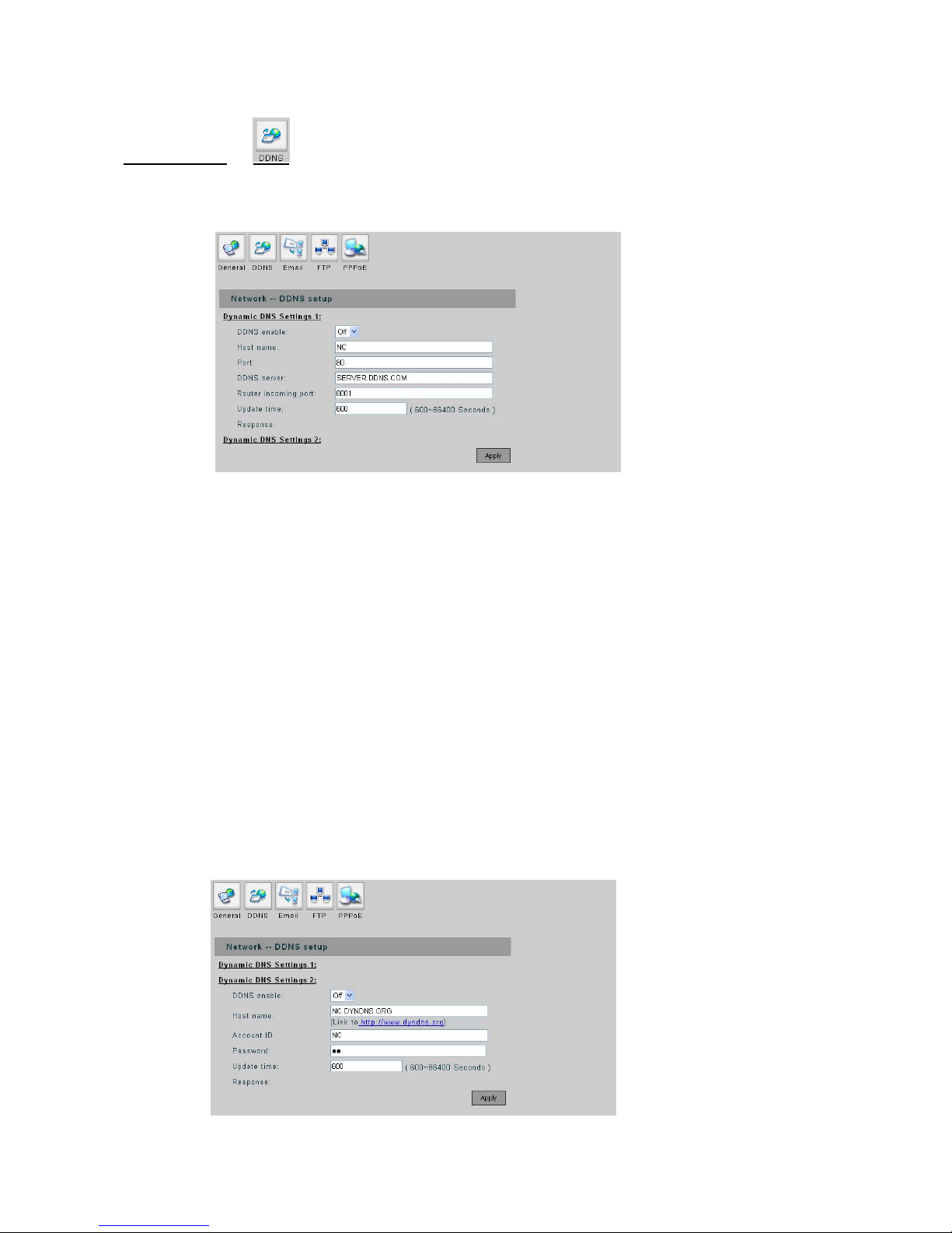
DDNS Setup
Dynamic DNS Settings 1:
- DDNS Enable: DDNS allows the dynamic IP address to be registered so others can conne ct to it by a
domain name. If you wish to use DDNS service and set to “ON”.
Host Name: As- sign a host name for the device, this name will be the domain name.
of the DDNS server.
change the port to match the Port
to detect the IP address and update to the DDNS server. The time
conds.
DDNS status.
n
- Port: Change the port if necessary.
- DDNS Server: Input the domain name
- Router Incoming Port: If the device is connected to a router,
Forwarding setting in the router.
- Update Time: Set the interval time
setting must be in the range 600~86400 se
- Response: After confirm the settings; a message will appear for check the
- Apply: Confirm the settings.
Dy amic DNS Settings 2:
Page 42
41
4
DDNS Enable: As in settings 1 mentioned.
- Host Name: As in settings 1 mentioned.
the rver needs an account to log in, the field here is then for the account identification.
r the account to log in.
Update Time: As in settings 1 mentioned.
- Response: As in settings 1 mentioned.
- Apply: Confirm the settings.
Email Setup
-
- Account ID: For se
- Password: password fo
-
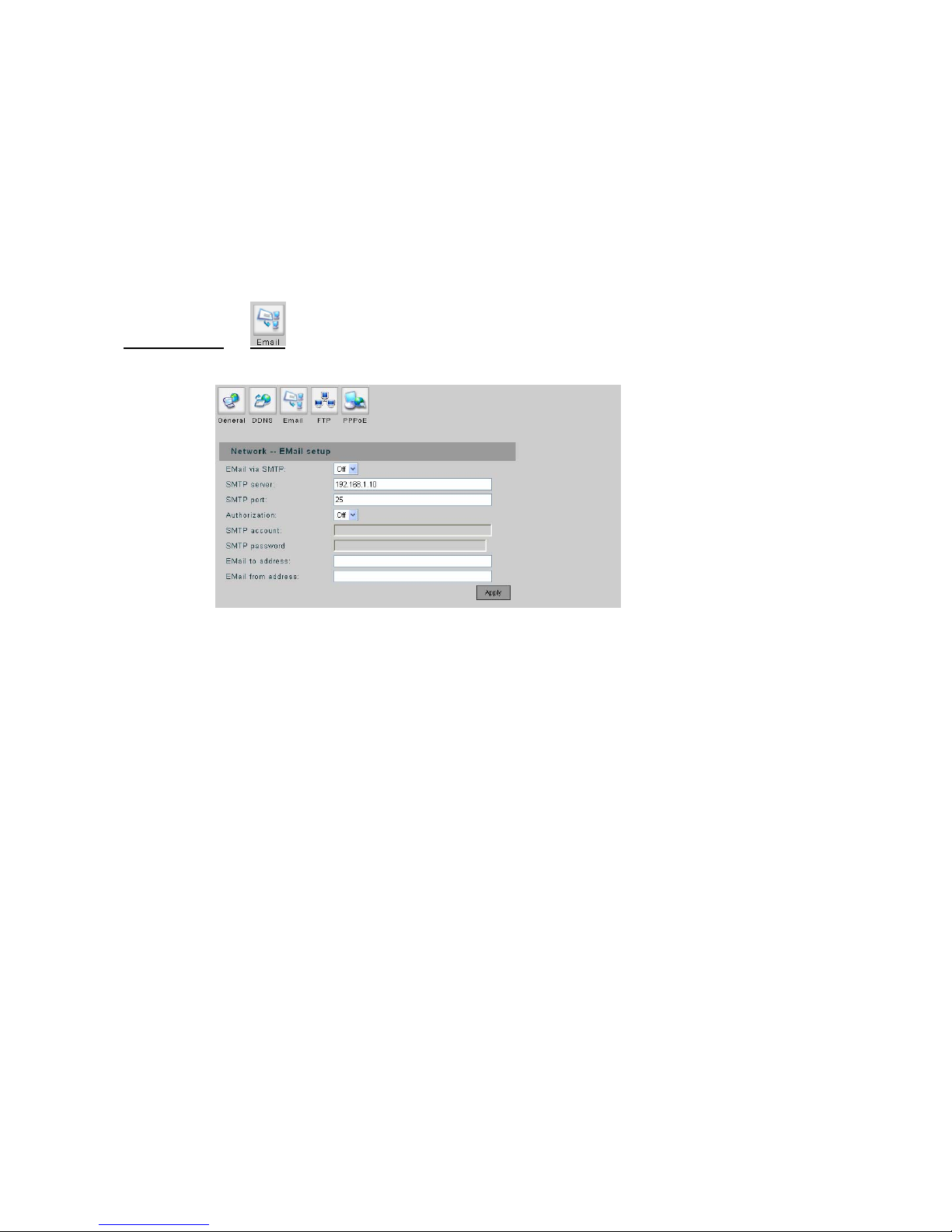
- Email via SMTP: Set to “ON” if use a SMTP server to send the Email.
SMTP Server: SMTP server IP a- ddress.
- s account and password.
have to fill up
ass through the authentication.
Email to Address: The Email address to receive the Email.
he Email address that send the Email.
Apply: Confirm the settings.
- SMTP Port: Change the port if necessary. Default is recommended.
Authorization: Set to “ON” if the Email service need
- SMTP Account / Password: If the SMTP server has enabled authentication function. You
the Account and Password to p
-
- Email from Address: T
-
Page 43
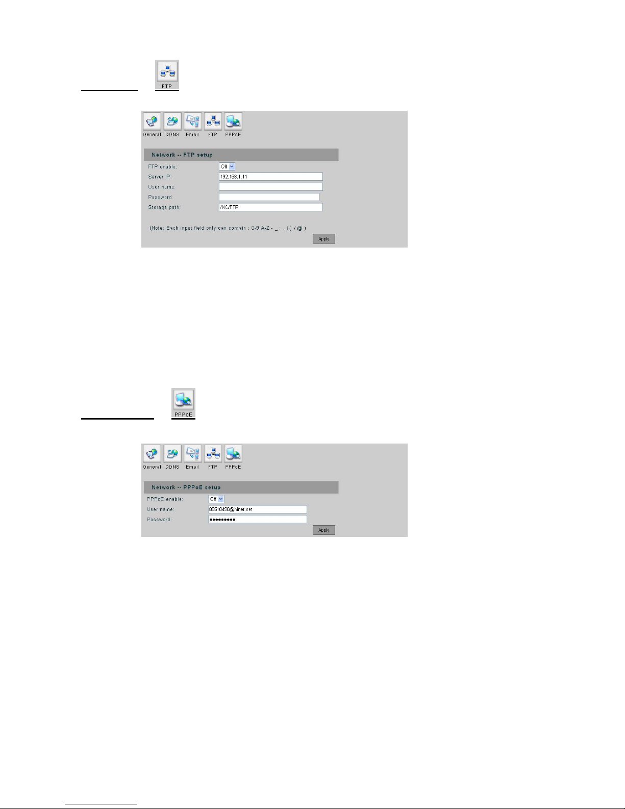
FTP Setup
- FTP enable: Set to “ON” if use a FTP server to receive the event notification.
- Server IP: Enter the IP address of the FTP server.
- User Name / Password: The account name and password to login the FTP server.
- Storage Path: Path of the FTP site to put the file.
- Apply: Confirm the settings.
PPoE Setup
42
4
P
- PPPoE enable: Enable/disable PPPoE function.
User name / Password: Account authentication; enter user name and password for the PPPoE
account.
Apply: Confirm the settings.
-
-
Page 44
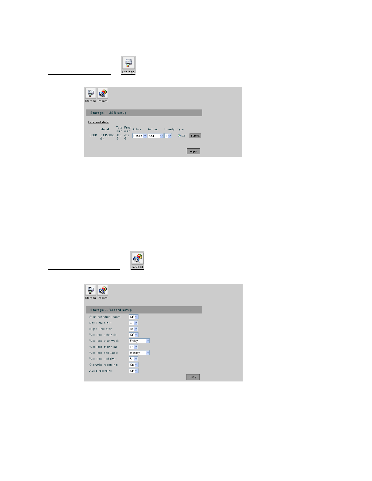
7. Storage Setup
43
4
Storage USB Setup
Display the information and status of the storage devices that connected to UNC7702.
“Backup”, or “Off” as taking no action.
iority disk will always be taken to act unless it is
Type: the disk will be formatted with EXT file system if “Record” is taken active, while EXT or FAT
file system can be applied for “Backup” activity
- Format: Format the disk with these conditions.
Storage Record Setup
- Active: represents the disk will act as a “Record” or
- Action: shows the disk’s mount status.
- Priority: Set the priority of the disk. The highest pr
full.
-
- Start Schedule Record: When set to “ON”, the re cording will de pend on the set d ay and night time,
or weekend time.
Day Time Start: Set the beginning time of the day.
Night Time Start: Set the beginning time of the night.
-
-
Page 45

44
4
hen set to “ON”, the weekend schedule will be enabled.
Time: Set the beginning day and time of the weekend.
- Weekend End Week / Time: Set the ending day and time of the weekend.
hen t to “ON”, if the record HDD is full, the recording will overwrite the
earliest recorded file in the HDD.
- Audio Recording: When set to “ON”, both video and audio will be recorded.
- Apply: Confirm the settings.
- “Record Hard Disk setting error!” This message shows when there is no storage to be set active.
- Weekend Schedule: W
- Weekend Start Week /
- Overwrite Recording: W se
Page 46
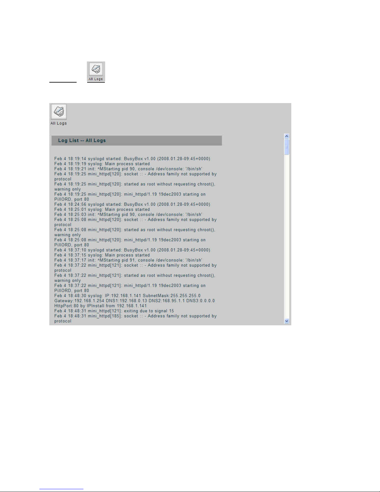
45
4
8.
Log
Log List
List
Page 47

46
4
Appendix A
Specifications
UNC7702
System Embedded Linux, 32-Bit RISC Processor, 8MB Flash ROM, 64M B SDRAM
Video Compression MPEG-4 / MJPEG, Dual streaming
Video Resolution
Full D1: NTSC = 720 x 480; PAL = 720 x 576
Half D1: NTSC = 720 x 240; PAL = 720 x 288
CIF: NTSC = 352 x 240; PAL = 352 x 288
Frame Rate Up to 30(NTSC) / 25(PAL)
Image Device 1/3” Sony S upe r HA D CC D
Lens Type Fixed Lens, Focal Length 6.0mm, F1.6
Horizontal Resolution More than 540 TV Lines
Minimum Illumination 0.1 Lux at F2.0
White Balance Auto
Backlight Compensation ON / OFF selectable
Auto Electronic Shutter ON / OFF selectable
Alarm In / Out 1 Input / 1 Output
Motion Detection Yes
Event System
FTP & Email
Alert Message
Yes
Network Interface
10/100 Base-T Ethernet
Optional IEEE 802.11b/g wireless LAN via USB (to be upgraded)
Protocols TCP(UDP)/IP, HTTP, FTP, Telnet, SMTP, DHCP, NTP, DDNS, RTSP, RTP/TCP(UDP)
Audio Capability 1 Built-in Microphone / 1 3.5mm Line out jack
Power Supply ACDC power adapter, output: DC 12V
Optional built-in PoE IEEE 802.3af
Operation Temperature 5oC ~ 45oC
Operation Humidity 20% ~ 80% RHG
Dimension (L x W x H) 135mm x 85mm x 40mm
Net Weight 600 g (approximately)
I/O Connectors
Two USB 2.0 Host ports for external storage or USB wireless LAN
One Mini-DIN for RS-485/RS-232/GPIN/GPOUT/Video loopback out
One Reset hole to restore factory defaults
One RJ-45 Ethernet connector
One DC In connector
Package Contents
y CD (manual and software) y One Ethernet cable y Stand for mount
y ACDC Power Adapter (Not included with PoE model)
Page 48
47
4
Appendix B
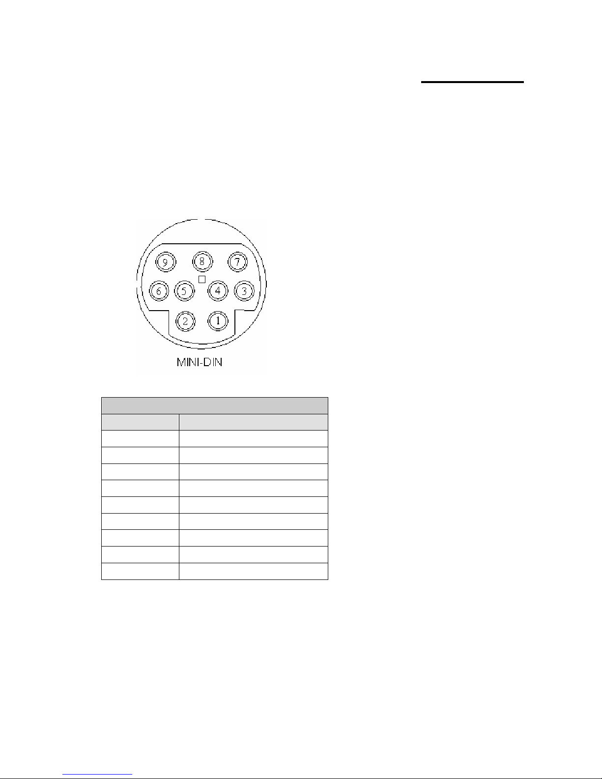
The Mini-din
The mini-din connector provides control signal input and output, which includin
Relay connection and one RS-485 port multiplex with COM port es connection of PTZ device
and external console to control the devi
Connector
g GPIO input, GPIO output as
. It also provid
ce.
COM / GPIO MINI-DIN
PIN FUNCTION
1 GPIN
2 RXD (Receive Data)
3 TXD (Transmit Data)
4 RS-485A
5 GND (System Ground)
6 GPOUT-Automatic Relay
7 GPO matic Relay UT-Auto
8 RS-485B
9 Video Out
GPIN: Input high when op when sinking more than 10mA or sho rting
to pin 5 (GND).
RXD (COM Port Receive D
TXD (COM Port Transmit
RS485A/RS485B: To connect with external PTZ devices, please contact your dealer/distributor to
get the information of the supported PTZ models.
ening the connection; input low
ata)
Data)
Page 49

48
4
GND (System Ground): System Ground is also connected to chassis as frame
GPOUT-Automatic Relay : When enable to use the GP IN or motion detectio n to
devices, the “Relay” must be turned on.
Video Out: Use the especial cable in the product pac
video to the monitor.
ground.
trigger some alarm
kage to connect this pin that it can output the
Page 50
Appendix C
49
4
Q
. How can I set factory default?
NS:
1. Unplug the power jack to turn off the power of UNC7702.
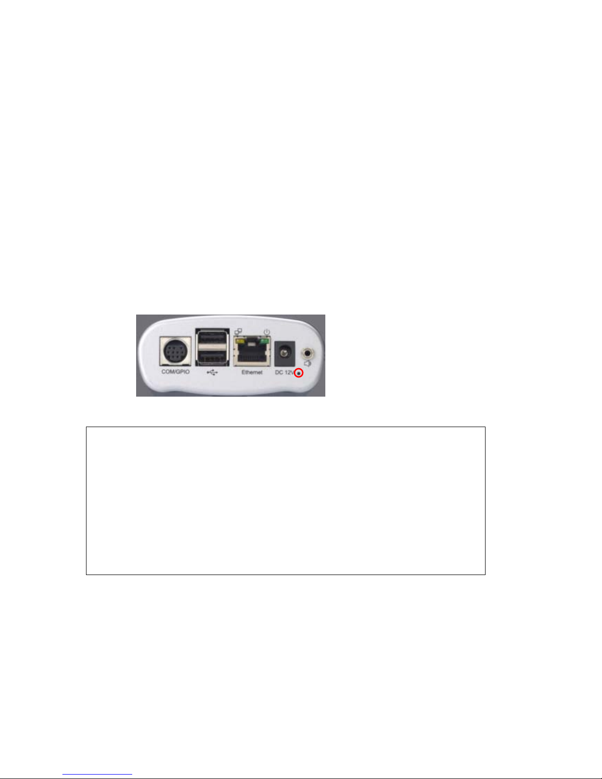
2. Insert a pin into the reset hole as circled with red in the below figures. Sense a button and keep
it pressed until instructed to release.
3. Plug in the power jack to turn on UNC7702, count 25 seconds (at least 20 seconds) and
release the button (remove the pin from the reset hole).
4. The UNC7702 should now be back to factory default. Have an access to the device by
changing to the attempt IP address from the default 192.168.0.200.
FA
1
A
UNC770
2
Note:
1. When UNC7702 can be scanned by IPInstaller with this IP “192.168.0.200” after factory
setting, it means the reset process is successful.
2. Within the 20~25 seconds, the reset progress will be launched. If the inserted pin is removed
before 20 seconds or after 25 seconds, the system wouldn’t take any effect; the reset will be
unsuccessful. Redo from step 1 for another chance.
3. Do not remove power any time in the reset process, the flash memory inside the device can be
damaged otherwise.
Page 51

50
5
2. How to upgrade firmware for the device?
ANS:
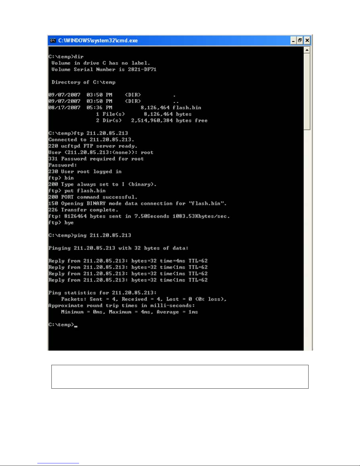
Download the newest software and unzip it into your local driver, for example "C:\temp". Then, con
the "flash.bin" file exists in this directory.
tton on Configuration page -> System ->
Commands.
St
For exampl
Enter DOS by "
Change to th
Start ftp session by enter “ftp <Device IP Address>
Enter "root" for USERNAME, "pass" for PASSWORD as default administrator; you will have to use
your administrator's USERNAME and PASSWORD to login if you ever added a user with
administrator authority.
Set FTP to binary mode using the command "bin".
In FTP session window, enter "bin"
In FTP n window, enter "put flash.bin"
In FTP
FTP se ansfer and automatically upgrade the software.
Use “pin uld
be able to a ws an
example of the whol
firm
Restart the device by clicking on the <Reboot> bu
Caution: You must reboot the device before doing the following procedures; otherwise, some
socca ional internal conflicts may endanger the Flash devices.
art the FTP session and log in to the UNC7702.
e, in our case for Windows XP:
Start > All Programs > Command Prompt."
e directory where the latest flash.bin exists.
Upload the software into the device by FTP "put" command.
sessio
session window, enter "bye" to quit FTP session.
ssion may freeze for around 1~2 minute to tr
g” to check whether the device is accessible. If you get replies after pinging, you then sho
ccess the device via Web interface. The figure of Com mand Prompt below sho
e operation.
Page 52
Note: Flash products can become damaged if the updating operation is not performed
correctly. So please follow up above procedures carefully.
51
5
Page 53
52
5
3. Why ActiveX remains in old version after upgrading to new version
firmware?
ANS:
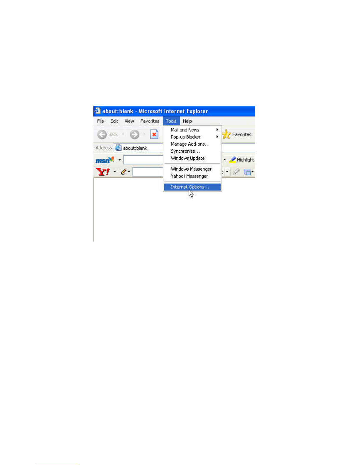
Launch an IE browser and click on “Tools” -> “Internet Options”. The Internet Options window then
shows up.
Page 54
53
5
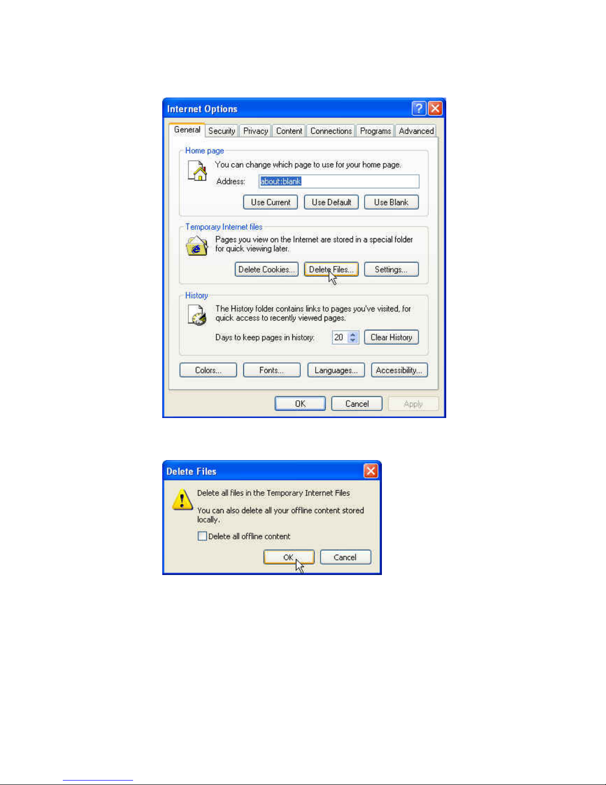
In Temporary Internet files, click on Delet e Files.
Press “OK” to confirm deletion.
Re-open IE browser and access to the device. You will this time be prompt to install newer version of ActiveX
ontrol. After installation, you should see the new version installed. c
Page 55
54
5
 Loading...