

Page 1
4-Port Wireless 11n Router (2T2R)
UGL2430-RTB
Quick Installation Guide
Copyright EUSSO Technologies, Inc. All rights reserved.
1 of 11
Page 2
※ To avoid users without access right through your WLAN Broadband
Router, suggest that use security mechanism like WEP, WPA or set
ID/password for web configuration login IP address 192.168.1.254.
Preparation.
1 At lease one PC with IEEE802.11b/g/n WLAN client installed.
2 One straight-through Category Ethernet cable, used to link WAN interface to xDSL or CM for
Internet connection.
3 WLAN Broadband Router.
Check package contents:
9 WLAN Broadband Router
9 DC Power Adapter
9 User’s manual CD-ROM
9 RJ-45 Cable Line
Collect Installation Information:
WAN configuration (Contact your ISP or network administrator for these information)
DHCP Client
Static IP
IP Address
Subnet Mask
Default Gateway
DNS Address
PPPoE
User Name
Password
PPTP
IP Address
Subnet Mask
FFF . FFF . FFF . FFF
FFF . FFF . FFF . FFF
FFF . FFF . FFF . FFF
FFF . FFF . FFF . FFF
FFF . FFF . FFF . FFF
FFF . FFF . FFF . FFF
Server IP Address
User Name
Password
L2TP
IP Address
Subnet Mask
2 of 11
FFF . FFF . FFF . FFF
FFF . FFF . FFF . FFF
FFF . FFF . FFF . FFF
Page 3
Server IP Address
User Name
Password
LAN configuration
FFF . FFF . FFF . FFF
IP Address
Subnet Mask
WLAN configuration
SSID
Mode
Channel Number
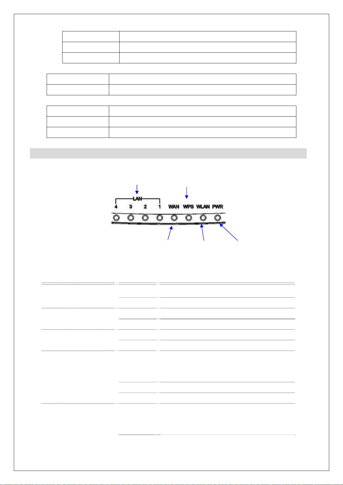
LED Panel Description
FFF . FFF . FFF . FFF
FFF . FFF . FFF . FFF
LAN LED
WPS LED
WAN LED
WLAN LED
Power LED
LED Indicator State Description
1. Power LED
2. WLAN LED
3. WPS LED
4. WAN LED
ACT
On The WLAN Broadband Router is powered on.
Off The WLAN Broadband Router is powered off.
Flashing WLAN is active
Off WLAN is off
Flashing The WPS feature is Enabled.
Off The WPS feature is Disabled.
.
Flashing Data is transmitting or receiving on the WAN
interface
5. LAN LED
ACT
On Port linked.
Off No link.
Flashing Data is transmitting or receiving on the LAN
interface.
3 of 11
Page 4
On Port linked.
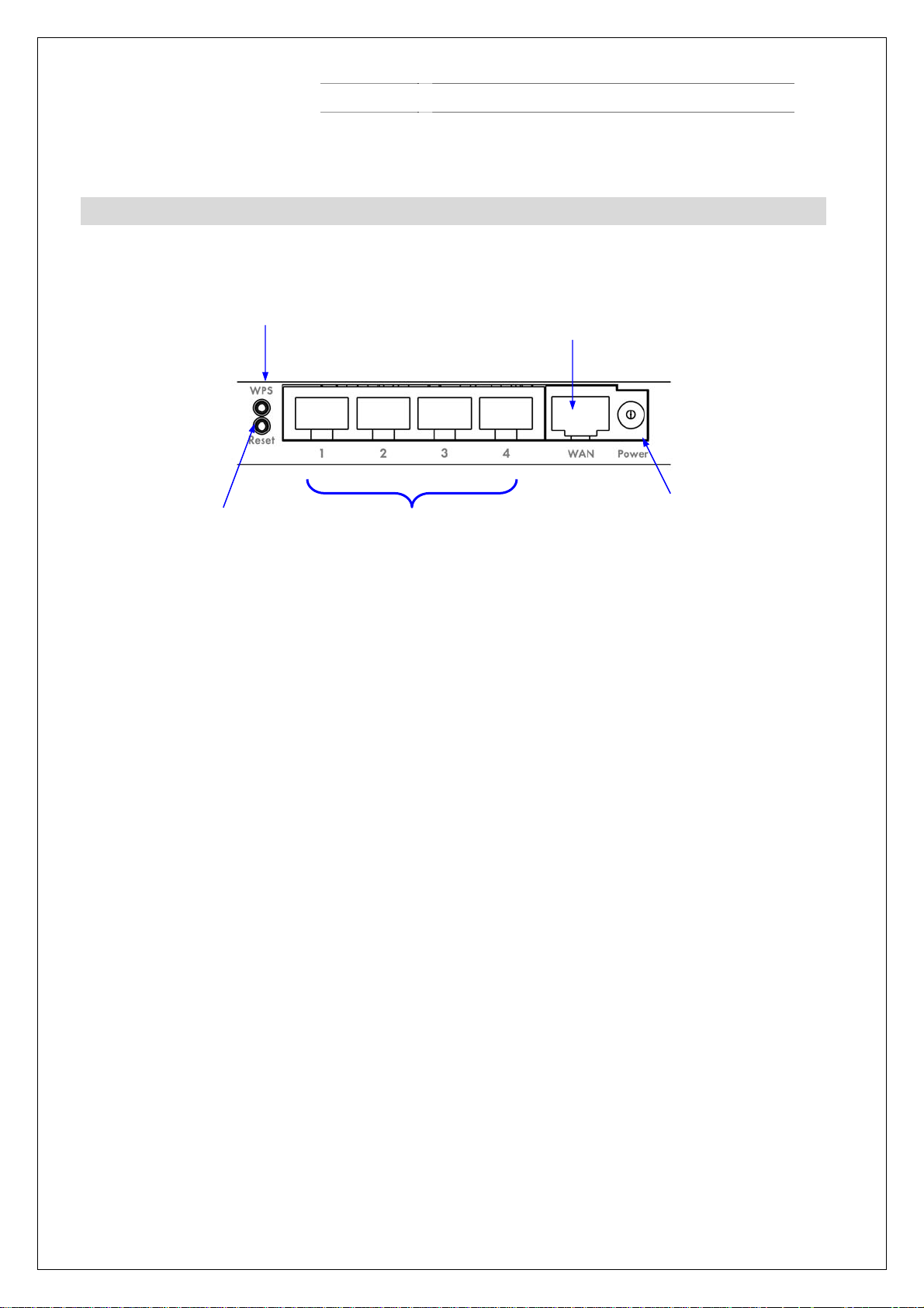
Back Panel Description
Type1
Reset
WPS
Off No link.
LAN
WAN
Power
4 of 11
Page 5
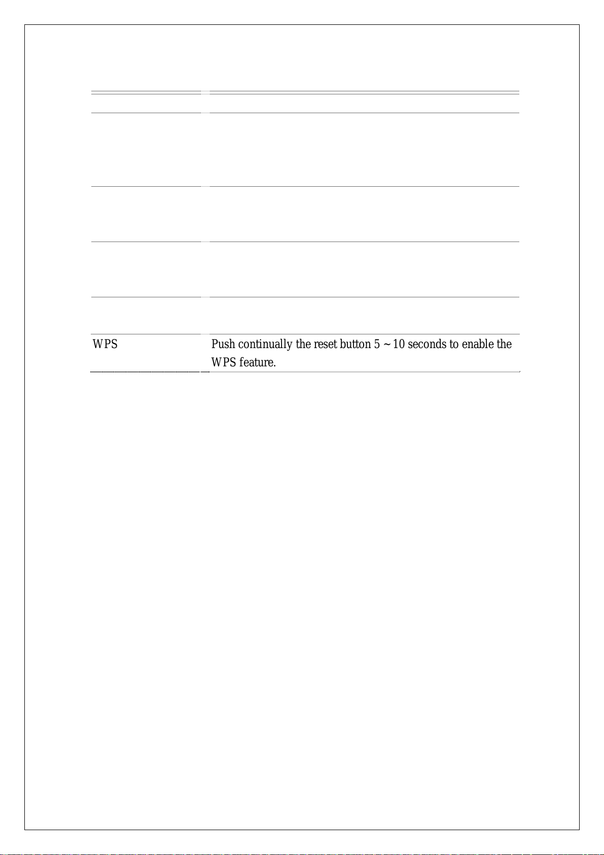
Interfaces Description
Wireless Antenna The Wireless LAN Antenna in box.
PWR (Power) The power jack allows an external DC power supply
connection.
The external DC adaptor provide adaptive power requirement
to the WLAN Broadband Router.
LAN The RJ-45 sockets allow LAN connection through Category 5
cables. Support auto-sensing on 10/100M speed and half/ full
duplex; comply with IEEE 802.3/ 802.3u respectively.
WAN The RJ-45 socket allows WAN connection through a Category
2 cable. Support auto-sensing on 10/100M speed and half/ full
duplex; comply with IEEE 802.3/ 802.3u respectively.
RS (Reset) Push continually the reset button 5 ~ 10 seconds to reset the
configuration parameters to factory defaults.
WPS Push continually the reset button 5 ~ 10 seconds to enable the
WPS feature.
5 of 11
Page 6
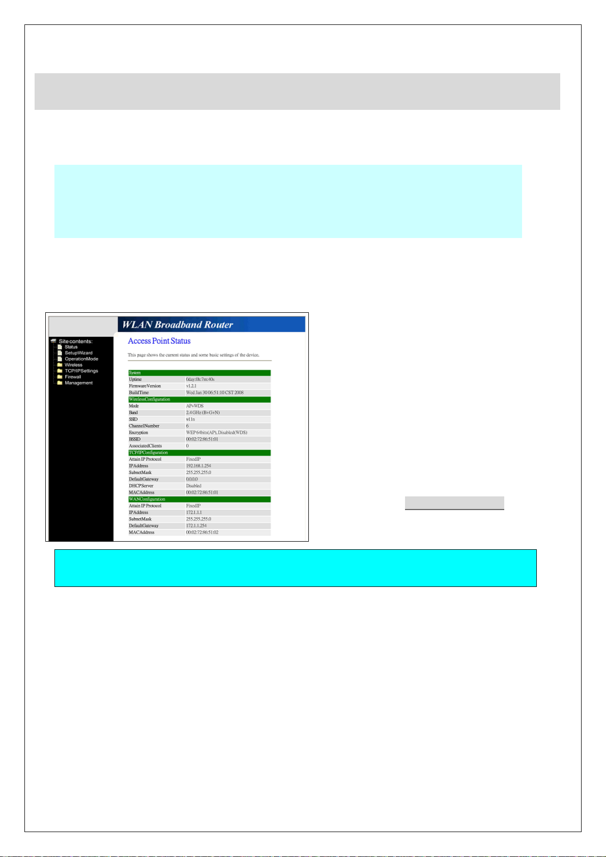
Installation.
Step One – Power On WLAN Broadband Router
Connect DC Power Adapter to WLAN Broadband Router and the wall power socket.
Notice: It will take about 50 seconds to complete the boot up sequence after powered on
the WLAN Broadband Router; Power LED will be active, and after that the
WLAN Activity LED will be flashing to show the WLAN interface is enabled
and working now.
Step Two – Configure WLAN Broadband Router
1. Connect your PC to LAN port for configuration setting. WLAN Broadband Router is delivered with
the following factory default parameters on the Ethernet LAN interfaces.
Default IP Address: 192.168.1.254
Default IP subnet mask: 255.255.255.0
WEB login User Name: <empty>
WEB login Password: <empty>
Configure your PC with IP address
between 192.168.1.1 to 192.168.1.253
and subnet mask to be 255.255.255.0,
then open an Internet browser (i.e.
Microsoft IE6.1 SP1 or above) to
connect WLAN Broadband Router by
entering http://192.168.1.254 to URL
field.
The following example is to configure router as “Gateway” mode that use factory default value.
You may change those values if you think that is necessary.
6 of 11
Page 7
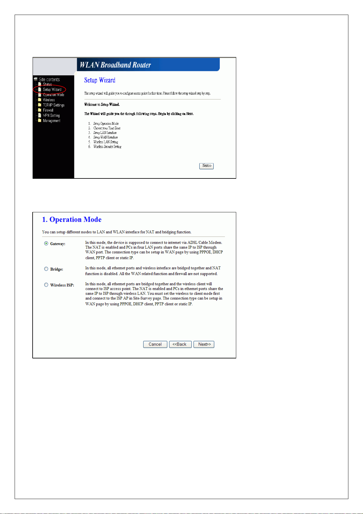
2. Click “Setup Wizard” in submenu of Site contents
3. Configure Operation Mode
Click “Next>>” button to
go next.
Click “Gateway”.
Click “Next>>” button to
go next.
7 of 11
Page 8
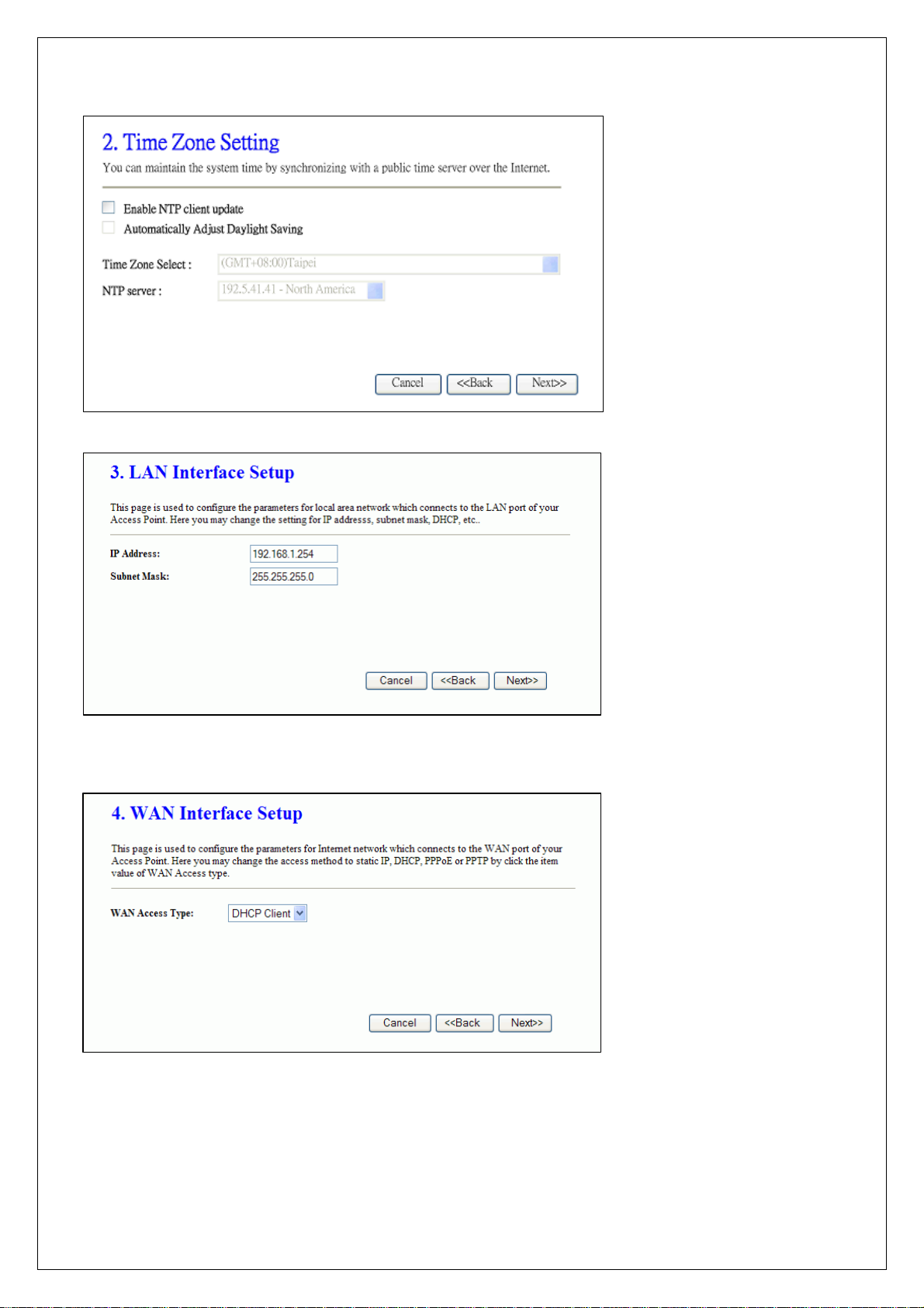
4. Configure Time Zone Setting configuration
5. Configure LAN Interface Setup
Click “Next>>” button to
go next.
IP Address:
192.168.1.254.
Subnet Mask:
6. WAN Interface Setup
255.255.255.0.
Click “Next>>” button to
go next.
WAN Access Type: Select
WAN connection of ISP
provides.
WAN Options:
Static IP, DHCP Client,
PPPoE, PPTP, L2TP
Click “Next>>” button to
go next.
8 of 11
Page 9
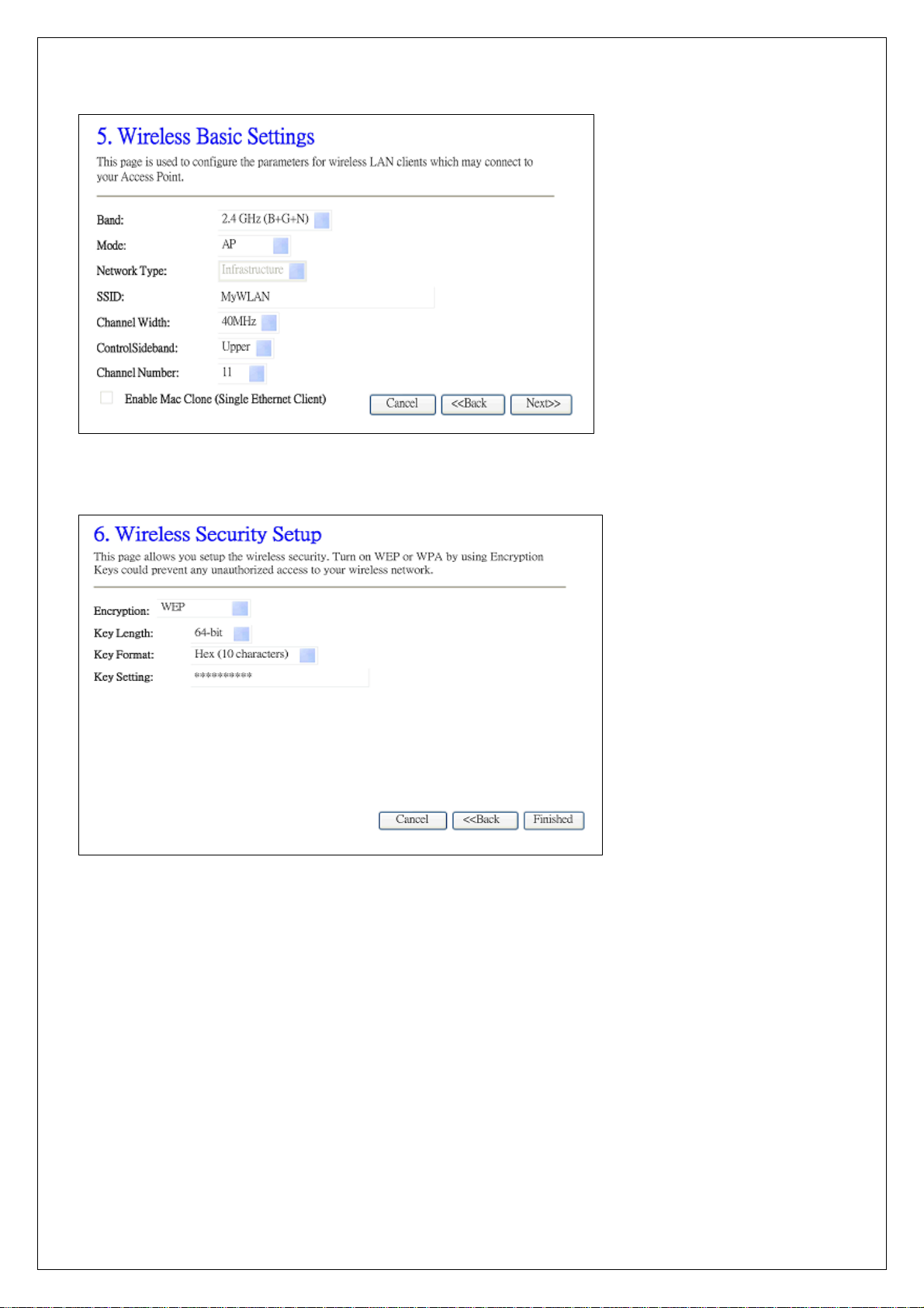
7. Wireless Basic Settings
8. Wireless Security Setup
Band: 2.4GHz(B+G)
Mode: AP
Network Type: disabled
SSID: MyWLAN
Channel: 11
Enable Mac Clone:
disabled
Click “Next>>” button to
go next.
Encryption: None
Options:
WEP, WPA (TKIP),
WPA2 (AES), WPA2
Mixed
Click “Finished” button to
close setup session.
9 of 11
Page 10
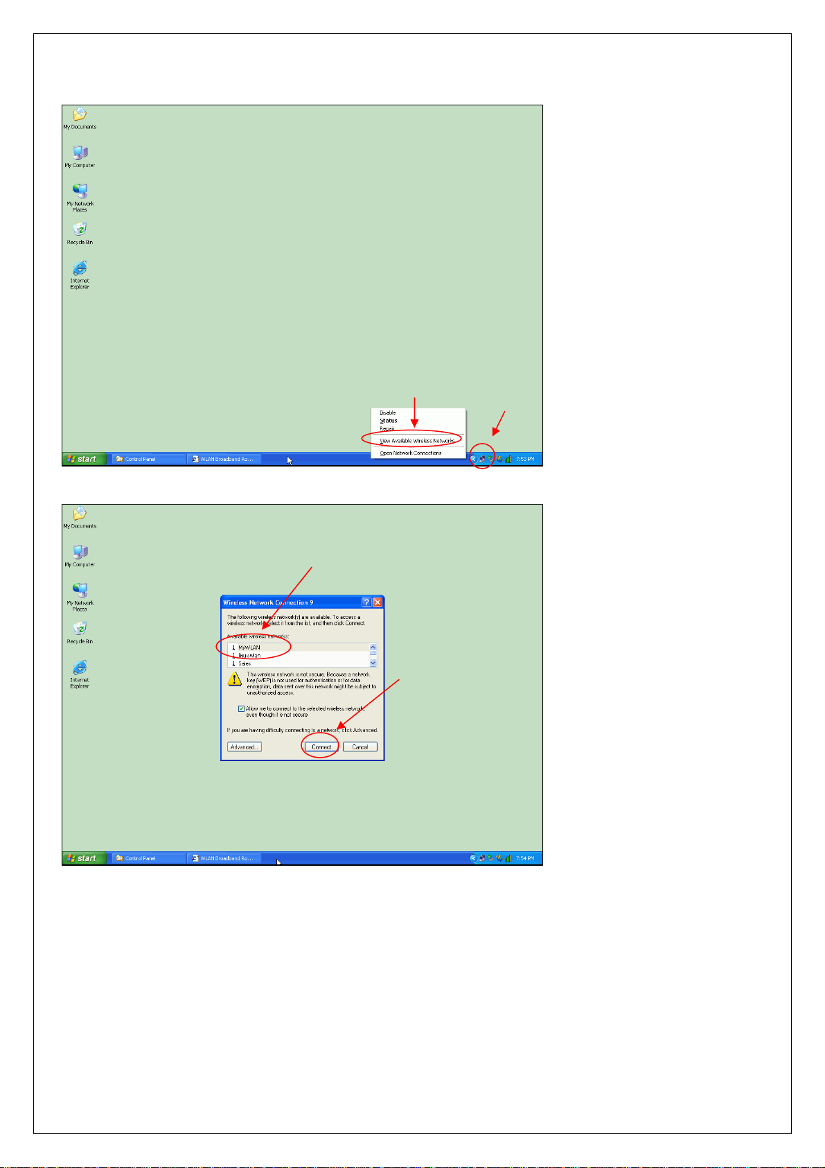
Step Three – Connect WLAN client to WLAN Broadband Router wirelessly
On your wireless client PC:
1. Move your mouse to the
Network icon on the Task
bar and right click the
mouse button to bring up
the pop-up menu.
2. Click the View Available
Wireless Networks on the
pop-up menu.
2
1
3
3. Select the specific WLAN
network (SSID) from the
Available Networks list.
4
4. Click the Connect button
to establish the
communication link to the
wireless network
10 of 11
Page 11
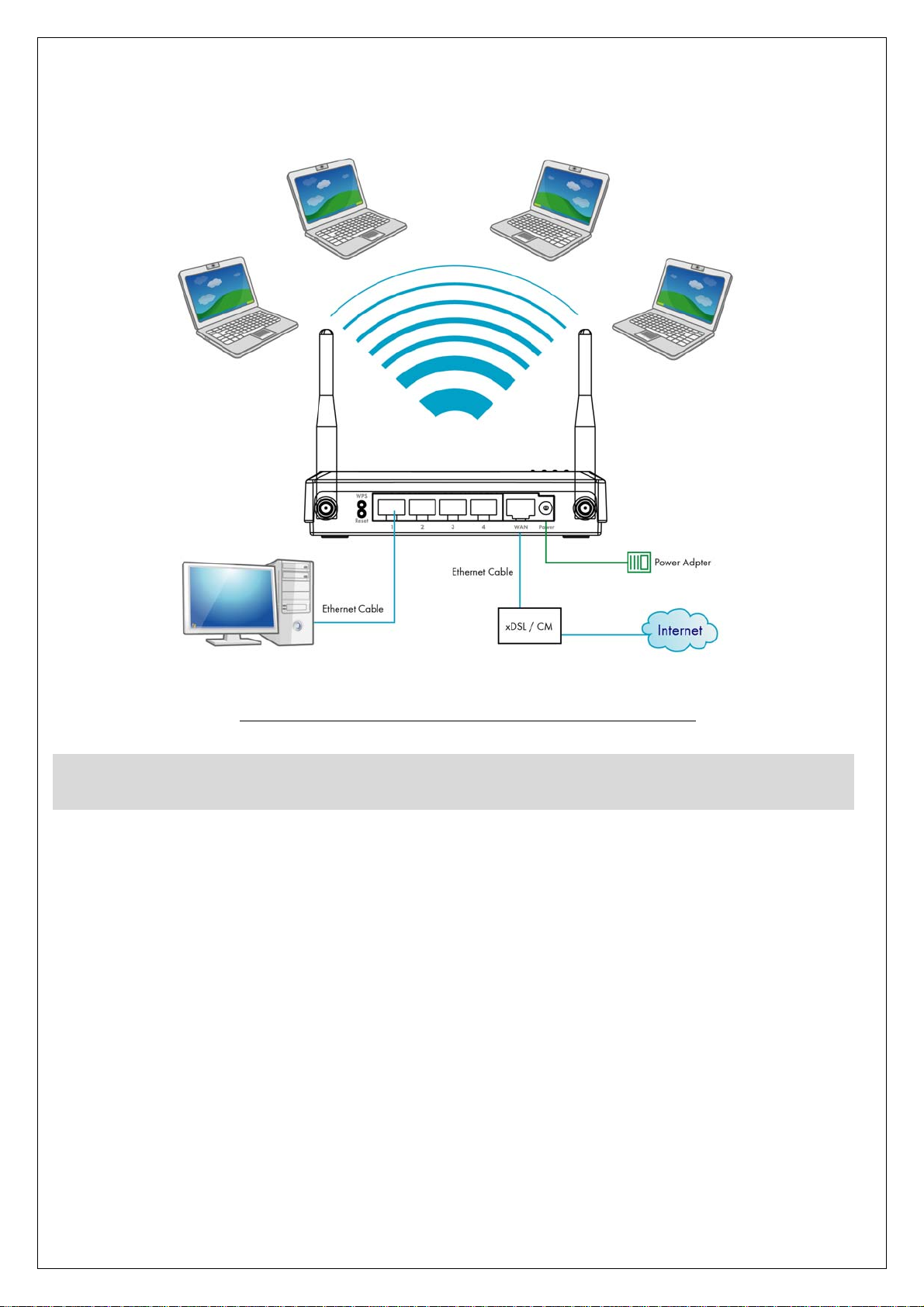
The wireless network diagram of WLAN Broadband Router..
Reference.
Please consult the user’s manual of WLAN Broadband Router for detailed and complete operation guide.
11 of 11
 Loading...