

Page 1

5/8/16-Port 10/100Mbps
Fast Ethernet Switch
User’s Manual
Page 2

FCC COMPLIANCE STATEMENT
This equipment generates and uses radio frequency energy and if not installed
and used properly, that is, in strict accordance with the instructions provided with
the equipment, may cause interference to radio and TV reception. The equipment
has been tested and found to comply with the limits for a Class B computing
device in accordance with the specifications in Subpart B of Part 15 of FCC rules,
which are designed to provide reasonable protec tion against such interference in a
commercial environment. However, there is no guarantee that interference will
not occur in a particular installation.
If you suspect this equipment is causing interference, turn your switch on and off
while your radio or TV is showing interference to determine the source of the
interference.
You can try to correct the interference by one or more of the following m easures:
1. Reorient the receiving radio or TV antenna where this m ay be done safely.
2. To the extent possible, relocate the radio, TV or the other receiver away
from the equipment.
3. Plug the computer which has the equipment installed into a different power
outlet so that equipment and the receiver are on different bra nch circuits.
If necessary, you should consult the place of purchase or an experienced radio/
television technician for additional suggestion.
CAUTION : The phone jack cannot be connected to telephone system.
Page 3

Contents
Chapter 1 Introduction ....................................1
Chapter 2 Features & Specifications ..............2
Chapter 3 Package Contents ...........................4
Chapter 4 Physical Description .......................5
Chapter 5 Installation ......................................7
Chapter 6 Trouble-shooting ............................8
Page 4
1
Introduction
1
Congratulations on your purchase of EUSSO’s 5/8/16-port desktop Fast Ethernet
Switch. This high performance switch provides five/eight/sixteen Fast Ethernet ports
to segment network traffic, extend Fast Ethernet connection distance, and convert
data packets between different transmission speeds. Importantly it provide the Auto
MDI/MDI-X function on all of UTP ports, so you don’t worry about whether the
cable is straight or cross-over type that you can easily connect it to the other switch
or hub.
This switch provides five/eight/sixteen shielded RJ-45 ports with 10Base-T/100BaseTX Auto-negotiation capability. All of UTP ports support full & half duplex modes
which are able to provide 200Mbps of bandwidth, The auto-negotiation function
providing smooth migration from Ethernet to Fast Ethernet.
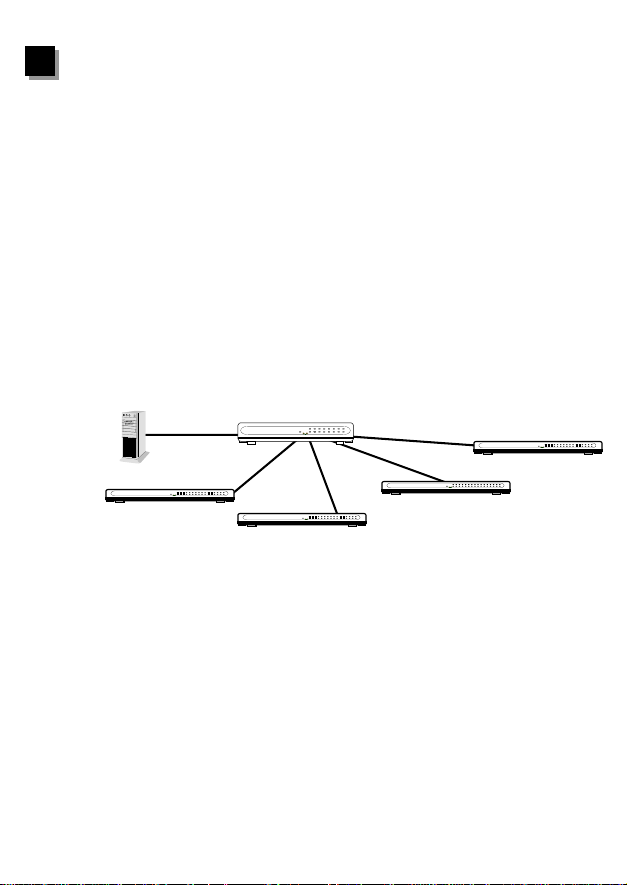
This switch is typically used to segment network traffics that can improve the
network performance by increasing the total bandwidth a s illustrated in Figure 1-1.
COL/FDX
1110 121314 1516
100Mbps
8-Port 10/100Mbps
Fast Ethernet Switch
16-Port
10/100Mbps
Fast Ethernet Switch
POWER
LNK/ACT
100Mbps
COL/FDX
POWER
LNK/ACT
321 456789
41526378
100Mbps
1110 121314 1516
100Mbps
16-Port
Fast Ethernet Switch
COL/FDX
16-Port
10/100Mbps
POWER
LNK/ACT
Fast Ethernet Switch
COL/FDX
10/100Mbps
POWER
LNK/ACT
321456789
1110 12 1314 15 16
321456789
200Mbps
COL/FDX
16-Port
10/100Mbps
POWER
LNK/ACT
Fast Ethernet Switch
35
321456789
Figure 1-1 Increase network bandwidth
This switch utilizes stored-and-forward switching architecture that filters and
forwards data after the complete data packet is received and examined to be free of
errors.
1110 121314 1516
With one set of status LEDs for each individual port, the switch operation status can
be easily monitored. Their slim and compact design allows direct placing on the
desktop or conveniently mounted on the wall or the side of a desk to accommodate
cabling consideration.
1
Page 5

2
Features & Specifications
2
(1) Features
Comply with IEEE 802.3 10Base-T Ethernet and 802.3u 100Base-TX Fast
Ethernet Standards.
Simple and economical way to bridge 10Base-T network and 100Bas e-TX
network.
Easily connect and segment Fast Ethernet hubs or segments.
All of RJ-45 ports support Auto-MDI/MDI-X function
All of RJ-45 ports support 10Base-T/100Base-TX and Full-Duplex /Half-Duplex
Auto-negotiation function.
Support store-and-forward switching architecture.
Slim and Compact design
2
Page 6

(2) Specifications
Standards : IEEE 802.3 and 802.3u
10/100Mbps Ports :
Switching Architecture : Store and Forward
Filter/Forward Rate : 148,800 packets/sec.
MAC Address :
Buffer :
Nway Auto-negotiation : all ports
Full-Duplex/Half-Duplex : all ports
LEDs :
System LED -- Power
Port LED -- Link/Activity, 100/10M
Di mensions :
Weight :
Power :
Operating Temperature : 32-131
Operating Humidity : 10-95% (Noncondensing)
Emission : FCC Class B, CE Mark & C-Tick
5 Port switch -- RJ-45 x 5 Auto-MDI/MDI-X
8 Port switch -- RJ-45 x 8 Auto-MDI/MDI-X
16 Port switch -- RJ-45 x 16 Auto-MDI/MDI-X
5 Port switch -- 2K
8 Port switch –8K
16 Port switch – 8K
5 Port switch -- 128KByte
8 Port switch -- 256KByte
16 Port switch -- 512KByte
5 Port switch -- 127 x 83 x 30 mm / 5.0 x 3.27 x 1.18 in.
8 Port switch -- 187 x 100 x 30 mm / 7.4 x 3.94 x 1.18 in.
16 Port switch -- 290 x 100 x 30 mm / 11.4 x 3.94 x 1.18 in.
5 Port switch -- 180g / 0.40lb.
8 Port switch -- 370g / 0.81lb
16 Port switch -- 480g / 1.06lb
5/8 Port switch -- 12V DC, 0.5A
16 Port switch -- 12V DC, 1A
0
F (0-550C)
3
Page 7
3
Package Contents
3
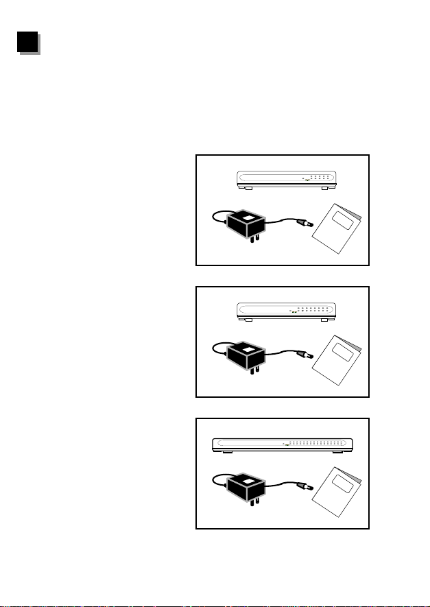
One Fast Ethernet Switch
One external power adapter
User’s manual
5-Port Fast Ethernet
Switch
8-Port Fast Ethernet
Switch
16-Port Fast Ethernet
Switch
5-Port 10/100Mbps
Fast Ethernet Switch
8-Port 10/100Mbps
Fast Ethernet Switch
16-Port
10/100Mbps
Fast Ethernet Switch
Figure 3-1 Package contents
4
COL/FDX
POWER
LNK/ACT
12345
COL/FDX
POWER
LNK/ACT
41526378
COL/FDX
POWER
LNK/ACT
321 456789
1110 12 13 14 15 16
Page 8
4
Physical Description
4
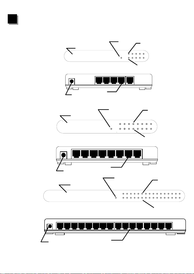
(1) Panel
5-Port Fast Ethernet
Switch
8-Port Fast Ethernet
Switch
16-Port 10/100Mbps
Fast Ethernet Switch
16-Port Fast Ethernet
LED Panel
5-Port 10/100Mbps
Fast Ethernet Switch
RJ45 Connectors
Power Connector
LED Panel
8-Port 10/100Mbps
Fast Ethernet Switch
RJ45 Connectors
Power Connector
LED Panel
Power LED
POWER
POWER
POWER
100M
LNK/ACT
Power LED
LNK/ACT
Power LED
100M
LNK/ACT
100M
100/10Mbps LED
12345
Link/Activity LED
10/100M LED
41526378
Link/Activity LED
100/10Mbps
31121019412513614715816
Link/Activity LED
Switch
Power Connector
RJ45 Connectors
Figure 4-1 Panel description
5
Page 9
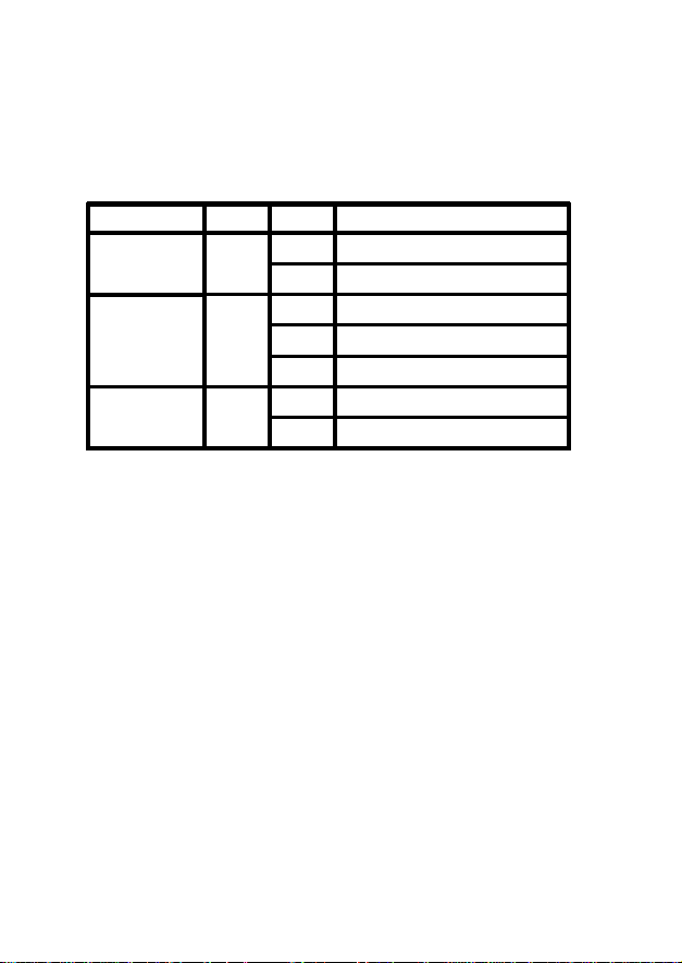
(2) LED
LED Color Status Description
PWR
(Power)
LNK/ACT
(Link/Activity)
SPEED
(10/100M)
Green
Lit
Off
Lit
Green
Flash
Off
Yellow
Lit
Off
Table 4-1 LED description
Power is supplied
No power
A valid link is established
Data packets received
No link is established
This port run at 100Mbps
This port run at 10Mbps
6
Page 10
5
Installation
5
1. Operating Environment
This switching hub must be installed and operated within the limits of specified
operating temperature and humidity (see previous sectio n under Specifications). Do
not place objects on top of the unit. Do not obstruct any vents at the sides of the unit.
Do not position the unit near any heating source such as heater,radiator, or direct
exposure to sun. Prevent entering of water and moisture into the unit. If necessary,
use dehumidifier to reduce humidity.
2. Connecting to network devices
The RJ-45 ports on the switch are supported Auto-MDI/MDI-X function which one
allow using straight-through or cross-over type to connect this switch to workstation
or hub.
Connect one end of the network cable to the RJ-45 port on the rear panel, and
connect the other end of the network cable to the RJ-45 port on the ne twork device.
Follow the same procedure to connect all the RJ-45 por ts of the switch. The UTP
network cables must comply with EIA/TIA 568 specifications and Category 5
standard for 100Mbps data transmission. Maximum length, using UTP cable,
between the switch and connected device is 100 meters (300ft) . Once the network
cable is connected to both ends and the attached network device is powered on, the
green LNK/ACT LED should be lit.
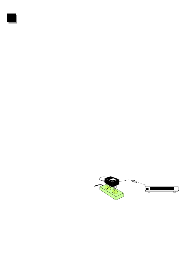
3. Connecting the power
Connect the output end of the power
adapter to the power connector on the
rear panel of the unit. Connect the
power adapter to the power outlet.
The green Power LED on the front
External Power Adapter
DC Power
AC Power
panel should be lit.
Figure 5-1 Connect the AC power adapter
7
Page 11

6
Trouble-shooting
6
1. Power LED is not lit
z Check if the power cord is properly connected to the external power adapter and
the power outlet. Make sure the DC power jack is firmly plugged into the power
socket of the switch.
2. Link/Activity is not lit when connect to 100Mbps device
z Check the power switch of the network device attached to the switch; make sure it
is turned ON.
z Check the network cable; make sure it is properly connected to the switch and the
network device.
z Check the network cable; make sure the UTP cables comply with EIA/TIA 568
and Category 5 specification.
[!] Contact your dealer if problem persist.
8
 Loading...