

Page 1

4 port / 8 port / 16 port
19” RACK MOUNTABLE
USB KVM SWITCH
USER’S MANUAL
Rev 1.0
Page 2

TABLE OF CONTENTS
TABLE OF CONTENTS………………………………………………..1
INTRODUCTION……………….……………………………………..2
FEATURES…………...……………………………………………….2
PACKAGE CONTENTS…………………………………………….3
TECHNICAL SPECIFICATIONS………..……………………………4
SYSTEM REQUIREMENT…………………………………………..5
CABLE DIAGRAMS………………………………………………….6
PRODUCT DETAILS…………………………………………………6
MAC O.S. and Sun Micro Systems Keyboard Mapping………6
HARDWARE INSTALLATION………………………………………7
USAGE…………………………………………………………………10
DAISY CHAIN CONNECTION DIAGRAM…………………………14
HOT PLUG……………………………………………………………15
ON SCREEN DISPLAY OPERATION……………………………15
TROUBLESHOOTING………………………..………………………21
CERTIFICATIONS……………………………………………………22
1
Page 3

Introduction
Thank you for purchasing USB KVM switch. 19” Rack Mount USB KVM switch can save
your MONEY, TIME, SPACE, EQUIPMENT and POWER.
Controlling multiple USB computers from One USB Keyboard, USB Mouse and VGA
Monitor. Rack Mount USB KVM switch is loaded with features such as 19” Rack Mount
Size, Daisy Chain up to Eight units, On Screen Display Menu, Password security,
Searching PC server name, Hot key Control, Push Button and Auto Scan Control. It has
complete keyboard and mouse emulation for simultaneous PCs boot-up process.
Features
4/8/16 port USB KVM switch is 19” rack mount size design
USB 1.1 Specification compliant
Support UHCI, OHCI USB interface
Support Win98/98SE/ME/2000/XP, WinNT, HP Unix, Linux, Sun Solaris, MAC O.S 8.6
or later version
Manage multiple PCs, G3/G4 MACs, iMACs, SUN Microsystems with USB port from
one USB keyboard, USB Mouse and Monitor.
Hot Plug - Add PCs or Remove Connected PCs for Maintenance without Powering
Down the KVM switch or PCs.
Very High Video Quality - Up To 1920X1440, Bandwidth: 200MHz
No Software Required - easy PC selection via On Screen Display Menu, Push Buttons,
Hot Keys
Support eight characters password protection and search PC server name
Plug N Play, No software driver needed for USB keyboard and USB mouse operation.
Auto Scan Mode for monitoring PCs and flexible Scan time from 5~99 seconds
Keyboard status restored when switching PCs
Support VGA DDC, DDC2, DDC2B.
LED Display for easy status monitoring
Buzzer sound for switching port confirmation.
Using 2-in-one cable (HDDB 15 pin male to HDDB 15 pin male and USB type A plug)
Built-in one extra daisy chain port and no waste any PC port
No DIP switch setting needed and auto detect daisy chain bank
2
Page 4
Package Contents
Model No.: 4 port Rack Mount USB KVM Switch
4 port USB KVM Switch 1 PCS
User’s manual 1 PCS
AC to DC Power Adapter 1 PCS
Rack Mount Kit 1 SET
Daisy Chain Cable 1 PCS
2-in-one PC port cable 4 PCS
Model No.: 8 port Rack Mount USB KVM Switch
8 port USB KVM Switch 1 PCS
User’s manual 1 PCS
AC to DC Power Adapter 1 PCS
Rack Mount Kit 1 SET
Daisy Chain Cable 1 SET
2-in-one PC port cable 4 PCS
Model No.: 16 port Rack Mount KVM Switch
16 port USB KVM Switch 1 PCS
User’s manual 1 PCS
AC to DC Power Adapter 1 PCS
Rack Mount Kit 1 SET
Daisy Chain Cable 1 SET
2-in-one PC port cable 4 PCS
3
Page 5
Technical Specifications
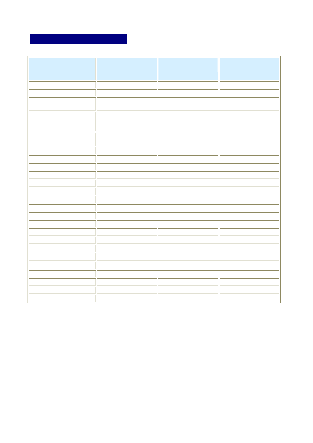
Model No. 4 port Rack Mount
USB KVM Switch
8 port Rack Mount
USB KVM Switch
16 port Rack
Mount USB KVM
Switch
PC Port 4 8 16
Console Port 1 1 1
PC Port Connector
(All Female Types)
Console Port Connector
(All Female Types)
Daisy Chain Port Connector
(All Female Types)
PC selection On Screen Display Menu, Hot Key, Push Button
PC Port LED 4 8 16
Bank 7 segment LED 1
On Screen Display Control Yes
Scan Intervals 5~99 Sec.
Keyboard Emulation USB
Mouse Emulation USB
VGA Resolution 1920X1440
Bandwidth 200MHz
Daisy Chain MAX Level 8
MAX PC Connection 116 120 128
Housing Metal
Power Adapter DC 12V 1A
Operation Temperature
Storage Temperature
Humidity 0~80%, Non-Condensing
Size 19” Rack Mount / 1RU 19” Rack Mount / 1RU 19” Rack Mount/ 1RU
Weight (kg) 1.9 2.0 2.2
Dimension (cm) 41(L) X 16.5(W) X 4.4(H) 41(L) X 16.5(W) X 4.4(H) 41(L) X 16.5(W) X 4.4(H)
VGA HDDB 15pin ( shared with USB port )
USB Keyboard USB-A type
USB Mouse USB-A type
VGA HDDB 15pin
VGA HDDB 15pin
0~50℃
-20 ~ 60℃
4
Page 6
System Requirements
Specifications:
Model No. 4 port Rack Mount USB KVM Switch
Console side One VGA Monitor
One USB Keyboard
One USB Mouse
Computer side 4 HDDB 15 pin male to one HDDB 15 pin
male and USB type A plug 4 pin special
cables
Model No. 8 port Rack Mount USB KVM Switch
Console side One VGA Monitor
One USB Keyboard
One USB Mouse
Computer side 8 HDDB 15 pin male to one HDDB 15 pin
male and USB type A plug 4 pin special
cables
Model No. 16 port Rack Mount USB KVM Switch
Console side One VGA Monitor
One USB Keyboard
One USB Mouse
Computer side 16 HDDB 15 pin male to one HDDB 15 pin
male and USB type A plug 4 pin special
cables
5
Page 7
Cable Diagrams
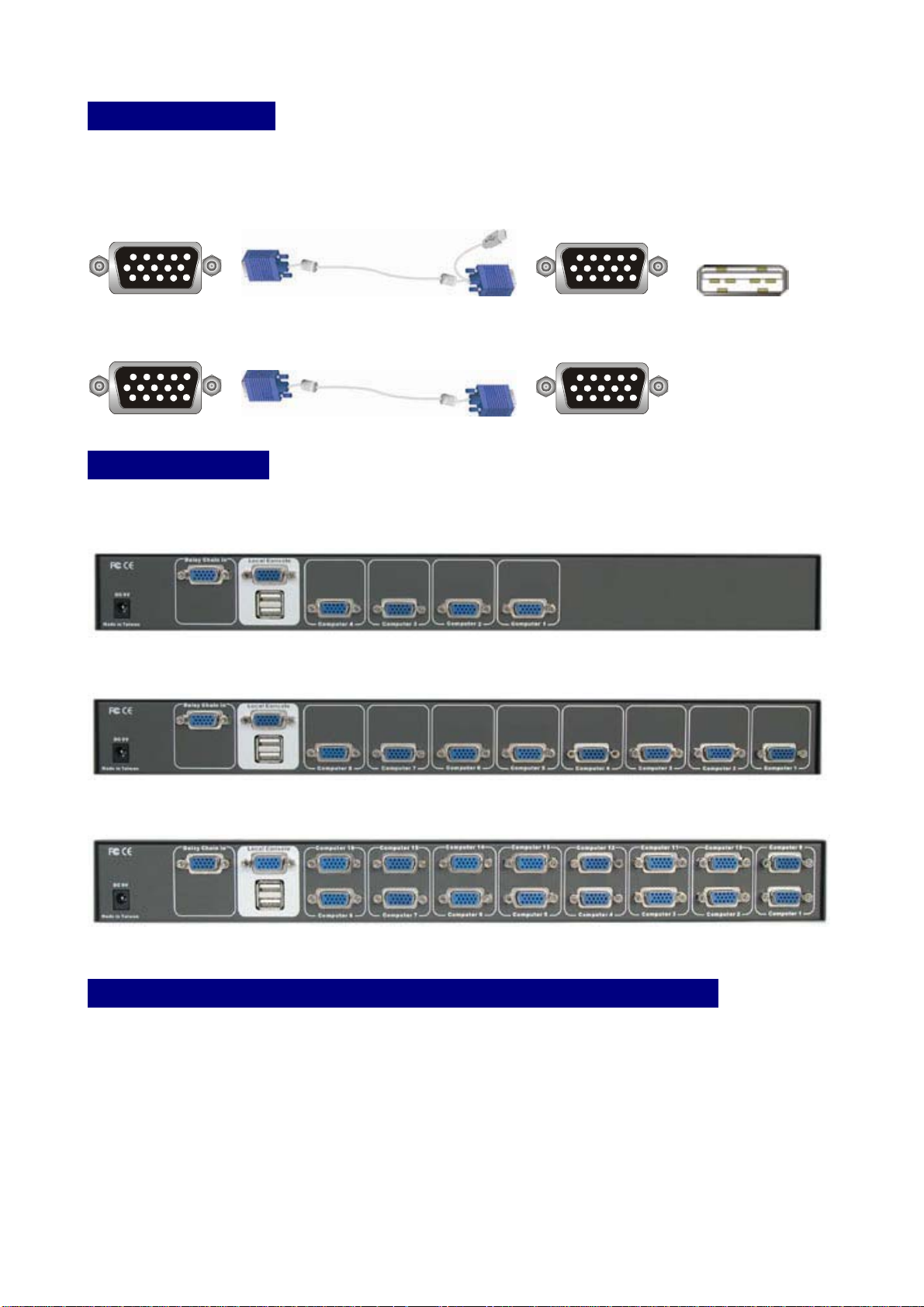
PC Port Special Cable:
HDDB15 pin Male to One HDDB 15 pin male and USB type A plug 4 pin special cable
Daisy Chain Cable:
HDDB15 pin Male to Male
Product Details
Front Panel & Rear Panel of 4 port Rack Mount USB KVM Switch:
Front Panel & Rear Panel of 8 port Rack Mount USB KVM Switch:
Front Panel & Rear Panel of 16 port Rack Mount USB KVM Switch:
MAC O.S. and Sun Micro Systems Keyboard Mapping
The following diagram indexes the Hotkey combination that emulates Mac O.S. and Sun
Micro keyboard commands. This feature is only available on the USB keyboard.
Left Windows Key = L_Win
6
Page 8
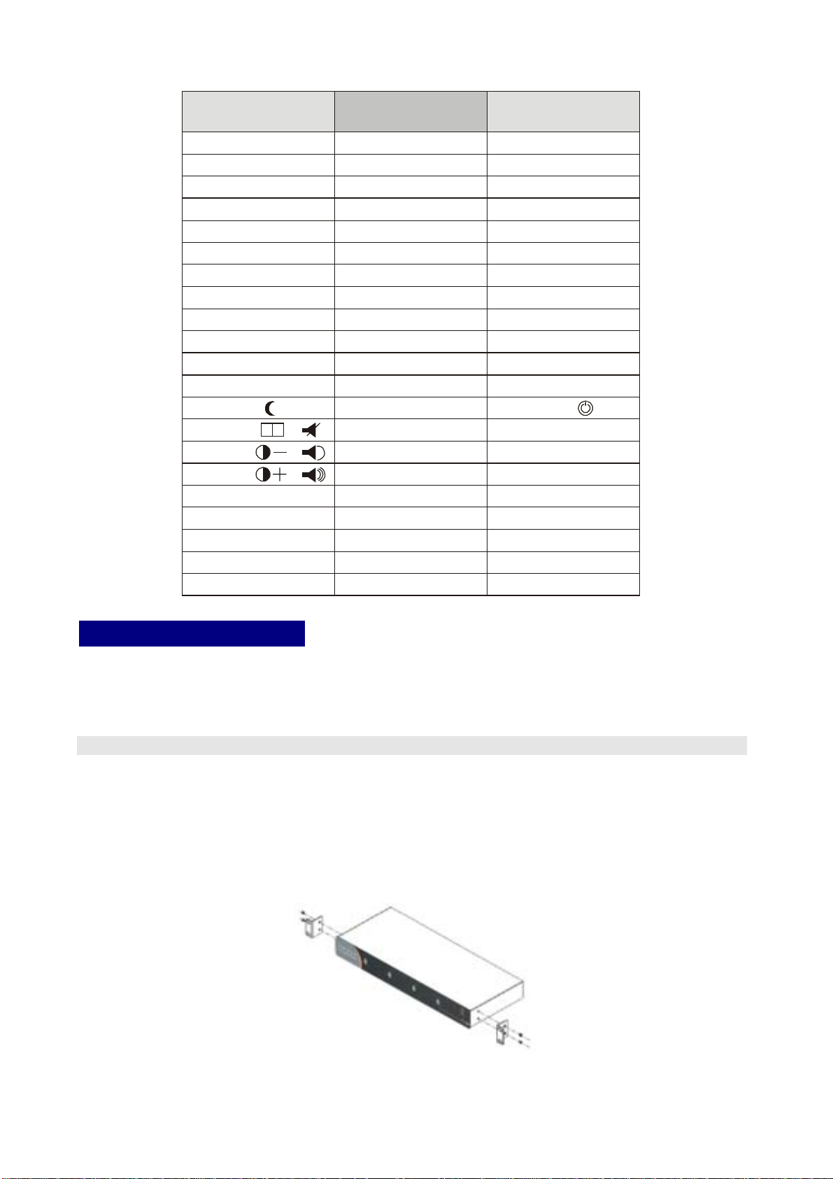
Sun Microsystems
Keyboard
Stop
Props
Compose
Front
Open
Find
Again
Undo
Copy
Paste
Cut
Help
Power
Mute
V_DN
V_UP
Windows ps2
Keyboard
L_Win & L_Alt
L_Win & L_Ctrl
L_Win & L_Shift
L_Win & F1
L_Win & F2
L_Win & F3
L_Win & F4
L_Win & F5
L_Win & F6
L_Win & F7
L_Win & F8
L_Win & F11
L_Win & F12
L_Win & "1"
L_Win & "2"
L_Win & "3"
Windows Key
Alt
Print Screen
Scroll Lock
Pause Break
Mac OS
Power
Apple Key
Option
F13
F14
F15
Hardware Installation
Before installation, please make sure all of peripherals and computers have been turned off.
This example of installation is based on 8 port USB KVM switch and you also can think that
4 port or 16 port USB KVM switch have the same installation procedures
Step 1
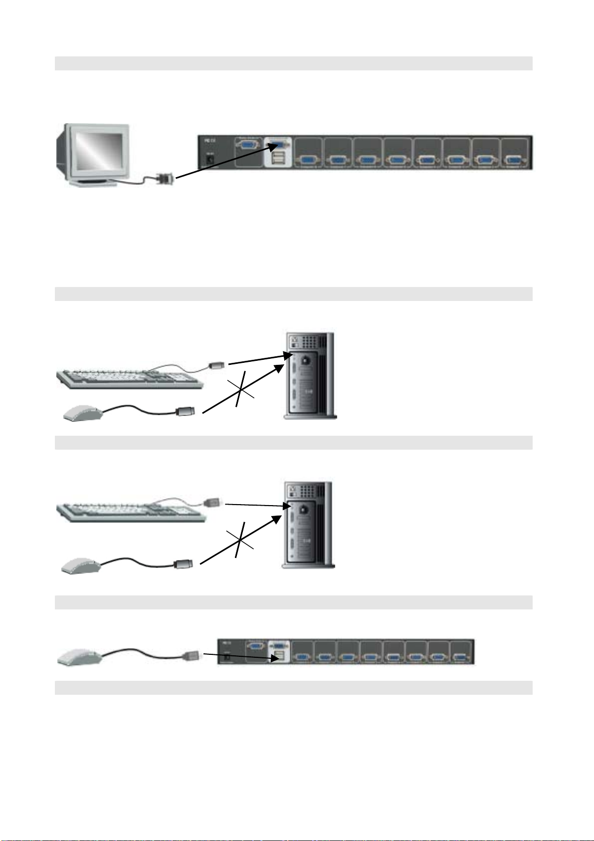
Find a convenient place to put your USB KVM Switch. Its 19” rack mount form factor makes
it ideal mountable on 19” rack. When mounting to a rack, attach the included brackets to
the sides of the USB KVM Switch. Take note of the length of your cables so that your
computers, USB KVM Switch, keyboard, mouse and monitor are distanced properly.
Attach the power adapter which included in this package to the USB KVM unit and plug the
other end into an electrical receptacle. Now you will see the LED for Port 1 light up, and
you will hear a beep.
7
Page 9
Step 2
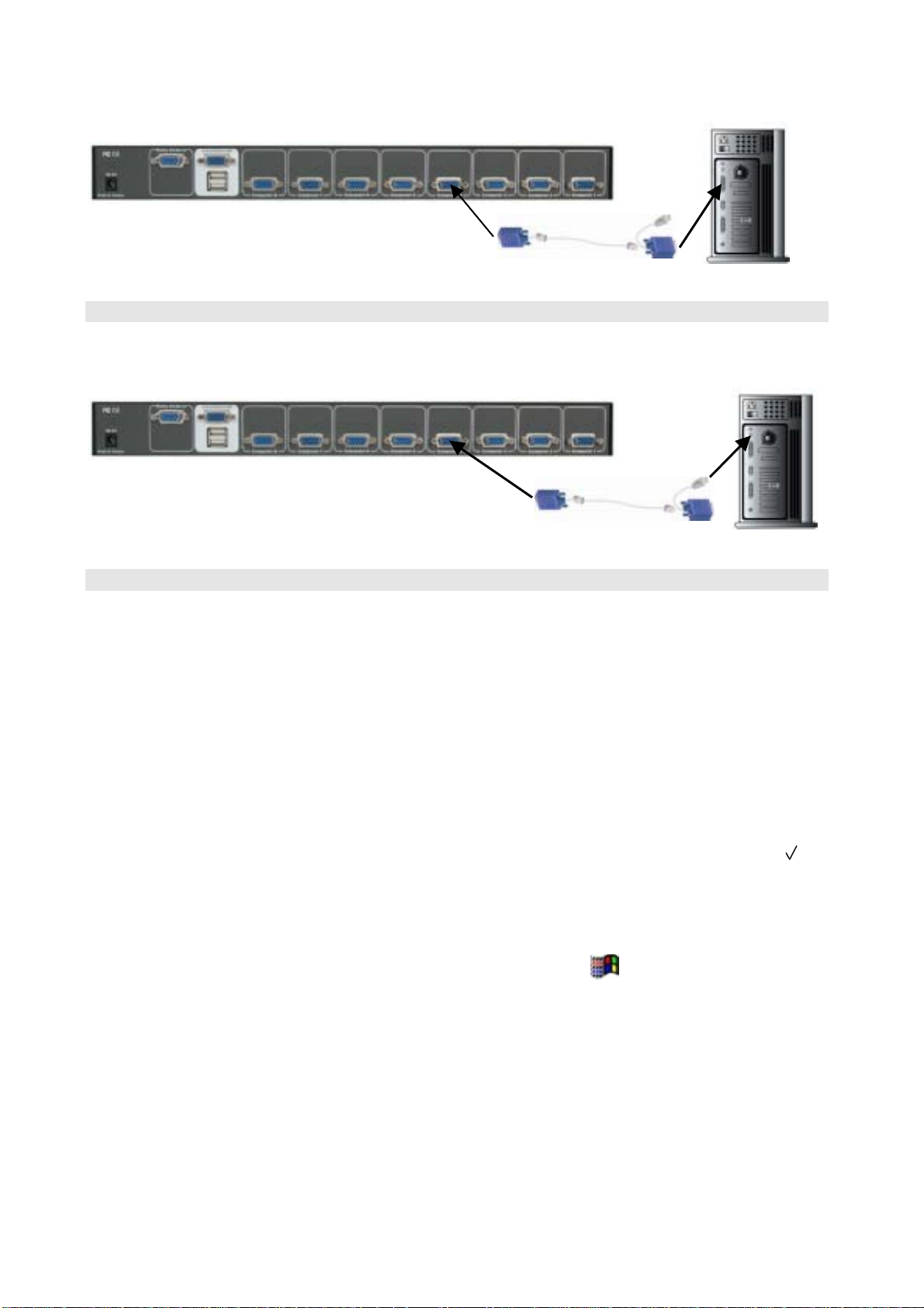
Connect the monitor to the USB KVM Switch. Using the attached cable, or the one included
with your monitor, connect it to the HDDB-15 female port on the back of the USB KVM unit
labeled with the monitor symbol at the CONSOLE port connector.
Note: For Windows ME/XP/NT/2000 user, please skip step 3 and go to Step 3-1
directly.
Step 3
For Windows 98/98SE/DOS user only:
Connect PS/2 keyboard to your PC PS/2 keyboard port directly and do not connect PS/2
mouse to your PC
Step 3-1
For Windows ME/XP/NT/2000 user only:
Connect USB keyboard to your PC USB keyboard port directly and do not connect PS/2
mouse to your PC
Step 4
Please connect the USB mouse to the USB KVM Switch’s USB mouse port.
Step 5
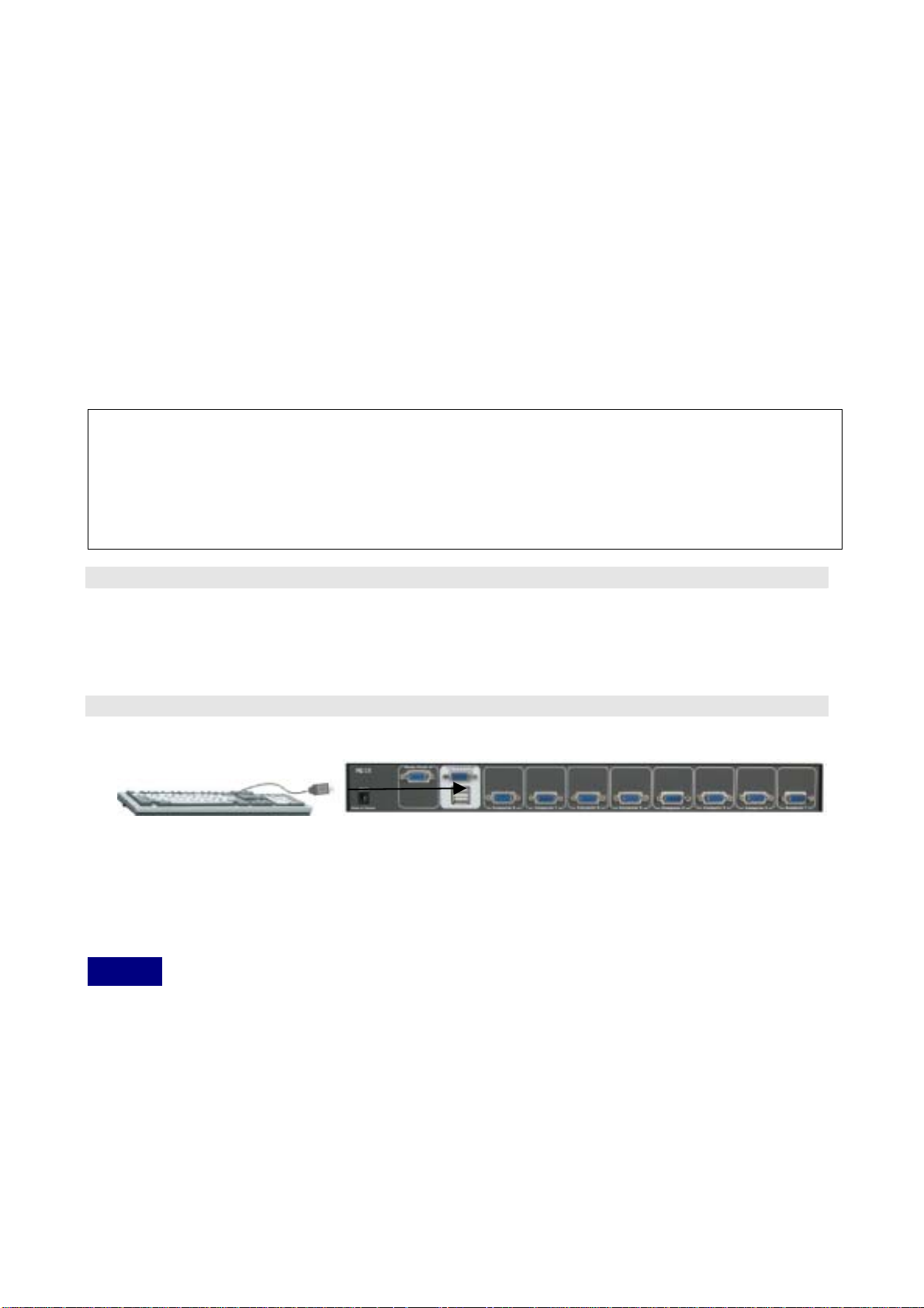
Now the PC connections will be made with the monitor (VGA) connections first. Connect a
2-in-one cable (15-pin HDDB Male to 15-pin HDDB Male and USB type A) with the VGA
male side to both of the PC and the rear panel of the USB KVM switch to the connector
labeled VGA.
8
Page 10
The rear side of PC
Step 6
Connect 2-in-one cable (15-pin HDDB Male to 15-pin HDDB Male and USB type A) USB
type A side cable to the PC.
The rear side of PC
Step 7
Windows 98/98SE user:
When you apply Windows 98/98SE to USB KVM Switch, please use the following set up
procedure:
1. Boot the PC and PC is unable to get the mouse during boot up system. The Window
O.S. will show the following message or similar things:
" Windows did not detect a mouse attached to the computer. You can safely
attach a serial mouse now. To attach a mouse to a PS/2 mouse port, you must
first turn the computer off.
□ Do not show this message in the future. "
Please use keyboard "Tab" key, "Space" bar and "Enter" key to select the item " □ Do
not show this message in the future." and finishing booting Windows O.S..
2. It will mount USB HID (Human Interface Device) driver. Using Keyboard “Tab” key, “Left
Arrow” key, “Right Arrow” key and “Enter” key to accomplish set up process.
3. Please turn off USB KVM Switch and use Windows key “ “ to shut down computers.
DOS User:
If the motherboard BIOS' USB port is disable in default mode and you apply USB keyboard
or USB mouse to PC. It does not work in DOS mode. Please disconnect USB keyboard or
USB mouse and connect PS/2 keyboard to the PS/2 port of PC for enabling BIOS USB
port.
Different motherboard BIOS has different USB port set up procedure. Here are some
examples, which based on some kind of BIOS version, below for the user reference.
9
Page 11
A. AWARD BIOS: To press "Del" key immediately for a couple of times when powering on
PC and you will get into BIOS set up mode→Select "Advanced" item →USB Legacy
support→Select "AUTO" →Save and quit BIOS set up.
B. PHOENIX BIOS:To press "F2" after powering on PC gets into BIOS set up mode→
Select "Advanced" item→Legacy USB support→Select "Enable" → Save and quit
BIOS set up.
C. AMI BIOS:To press "Del" key immediately for a couple of times when powering on PC
and you will get into BIOS set up mode → Select "Chipset features setup" → USB
controller→all USB port USB KB/Mouse→ KEYB+MOUSE → Save and quit BIOS set
up.
Note: If the PC BIOS need check keyboard to accomplish boot up process and the PC
might show keyboard error message on the screen, please configure the BIOS setting
again.
When you enter BIOS set up mode, please select the item “Halt on Error” or the other
Error condition setting and select “Halt all errors but Keyboard” or to ignore keyboard
during boot up BIOS process.
Step 8
1. For Windows 98/98SE/DOS user, Please repeat step 3 to 7 for the remainder of the
computers.
2. For Windows ME/XP/NT/2000 user, Please repeat step 3-1 to 6 for the remainder of
the computers.
Step 9
Connect the USB Keyboard to the USB KVM Switch.
Note: For MAC or Sun Microsystems user, please follow up the similar installation
procedure like Windows ME/XP/NT/2000.
Usage
The power on state of 4/8/16 port KVM switch:
When you power on KVM switch, it will ask you the password, the default password value
is eight zero –“ 00000000 “. Please key in eight zero and enter the same value at retype
field.
Note: Before you are not familiar with the operation of OSD menu, please don’t change the
password – i.e. keep default eight zero (00000000) value. Otherwise, if you have set the
password and unfortunately forget the password, you need send it back to your distributor
for maintaining the password.
10
Page 12
Pressing BANK Button to change BANK, and each BANK button assigns the channel to
designated PORT.
The LED display shows the Power On PC.
4 port Rack Mount USB KVM Switch
The Push Buttons :
Pressing the individual button to get PC port you want.
Reset Button (
(“ Bank ” button) and (“ PC 4 ” button ) ):
To press both “PC 4 ” button and “ Bank ” button of master bank simultaneously can reset
KVM switch. This reset action will not only return KVM switch back to initial state --- Check
the password, but also re-check all of slave banks which connected to mast KVM Switch.
If you add a new KVM Switch as a slave bank, please use reset button of master KVM
Switch to automatically assign a new ID to it. You can view this new slave bank go through
OSD menu. The PC ports of KVM Switch does not be reset by reset command.
PC port LED Indication:
There are two LEDs--- Power LED (The LED is marked by “ P “) and Link LED (The LED
is marked by “ O “) accompanied with each PC port.
When you select one of four PC ports and this PC is shut down or this PC port is
disconnected to the PC, the selected power port LED is off (But, if this PC is PC99 type, the
selected power port LED is lit) and the Link LED is flash. When you select one of four PCs
ports and this PC is powered on, the selected port Link LED is lit.
8 port Rack Mount USB KVM Switch
The Push Buttons :
Pressing the individual button to get PC port you want.
Reset Button (
(“ Bank ” button) and (“ PC 8 ” button ) ):
To press both “PC 8 ” button and “ Bank ” button of master bank simultaneously can reset
KVM switch. This reset action will not only return KVM switch back to initial state --- Check
the password, but also re-check all of slave banks which connected to mast KVM Switch.
If you add a new KVM Switch as a slave bank, please use reset button of master KVM
Switch to automatically assign a new ID to it. You can view this new slave bank go through
OSD menu. The PC ports of KVM Switch does not be reset by reset command.
PC port LED Indication :
There are two LEDs--- Power LED (The LED is marked by “ P “) and Link LED (The LED
is marked by “ O “ ) accompanied with each PC port.
When you select one of eight PC ports and this PC is shut down or this PC port is
disconnected to the PC, the selected power port LED is off (But, if this PC is PC99 type, the
selected power port LED is lit) and the Link LED is flash. When you select one of eight PCs
ports and this PC is powered on, the selected port Link LED is lit.
16 port Rack Mount USB KVM Switch
The Push Buttons :
Pressing the individual button to get PC port you want.
To press both “ Shift “ button and port 1(or port 2, 3,4,5,6,7,8) individual button
11
Page 13
simultaneous to get PC port 9 (10,11,12,13,14,15,16) respectively.
For example: The user would like to switch console port to PC port 12. He can press
“ Shift “ button and port 4 button simultaneously. The port LED of PC port 12 is lit when the
console is switched to PC port 12.
Reset Button (
(“ Bank ” button) and (“ PC 8 ” button ) ):
To press both “PC 8 ” button and “ Bank ” button of master bank simultaneously can reset
KVM switch. This reset action will not only return KVM switch back to initial state --- Check
the password, but also re-check all of slave banks which connected to mast KVM Switch.
If you add a new KVM Switch as a slave bank, please use reset button of master KVM
switch to automatically assign a new ID to it. You can view this new slave bank go through
OSD menu. The PC ports of KVM Switch does not be reset by reset command.
16 port Rack Mount USB KVM Switch (16 Ports)
PC port LED Indication :
There are two LEDs--- Power LED (The LED is marked by “ P “) and Link LED (The LED
is marked by “ O “ ) accompanied with each PC port.
When you select one of sixteen PC ports and this PC is shut down or this PC port is
disconnected to the PC, the selected power port LED is off (But, if this PC is PC99 type, the
selected power port LED is lit) and the Link LED is flash. When you select one of sixteen
PCs ports and this PC is powered on, the selected port Link LED is lit.
Note: If there are one of rack mount of KVM switches you used is 16 port USB KVM switch,
please put 16 port USB KVM switch on the 1st bank ( or say Master bank). It is based on 16
port USB KVM switch supports 16 port LEDs display on the front panel. Otherwise, 4 port
or 8 port USB KVM switch is allocated at 1st bank and there is a 16 port USB KVM switch
chained to the slave bank, the master bank ( or say 1st bank ) is unable to show the PC port
LEDs ( from port 9 to 16 ) of 16 port USB KVM switch completely.
7-Segment BANK LED Indication
When you would like to view the next bank KVM switch, please press “ BANK “ push button
cyclically to the destination bank. The bank LED will be changed from bank 1 to the
maximum daisy chain level and then to press “ BANK “ push button once back to the bank
1.
Bank 1 Bank 2 Bank 3 MAX BANK
Keyboard Hot Key Commands:
You can also conveniently command KVM switch by switching ports through simple key
sequences. To send commands to KVM switch, the “SCROLL LOCK” key must be
pressed twice within 2 seconds. You will hear a beep for confirmation and the keyboard
is in hot key mode. If you have not pressed any key in hot key mode within 2 seconds (It
means to key in any key follows up “Scroll Lock” “Scroll Lock” key ), the keyboard will back
to under Operation System control state.
12
Page 14
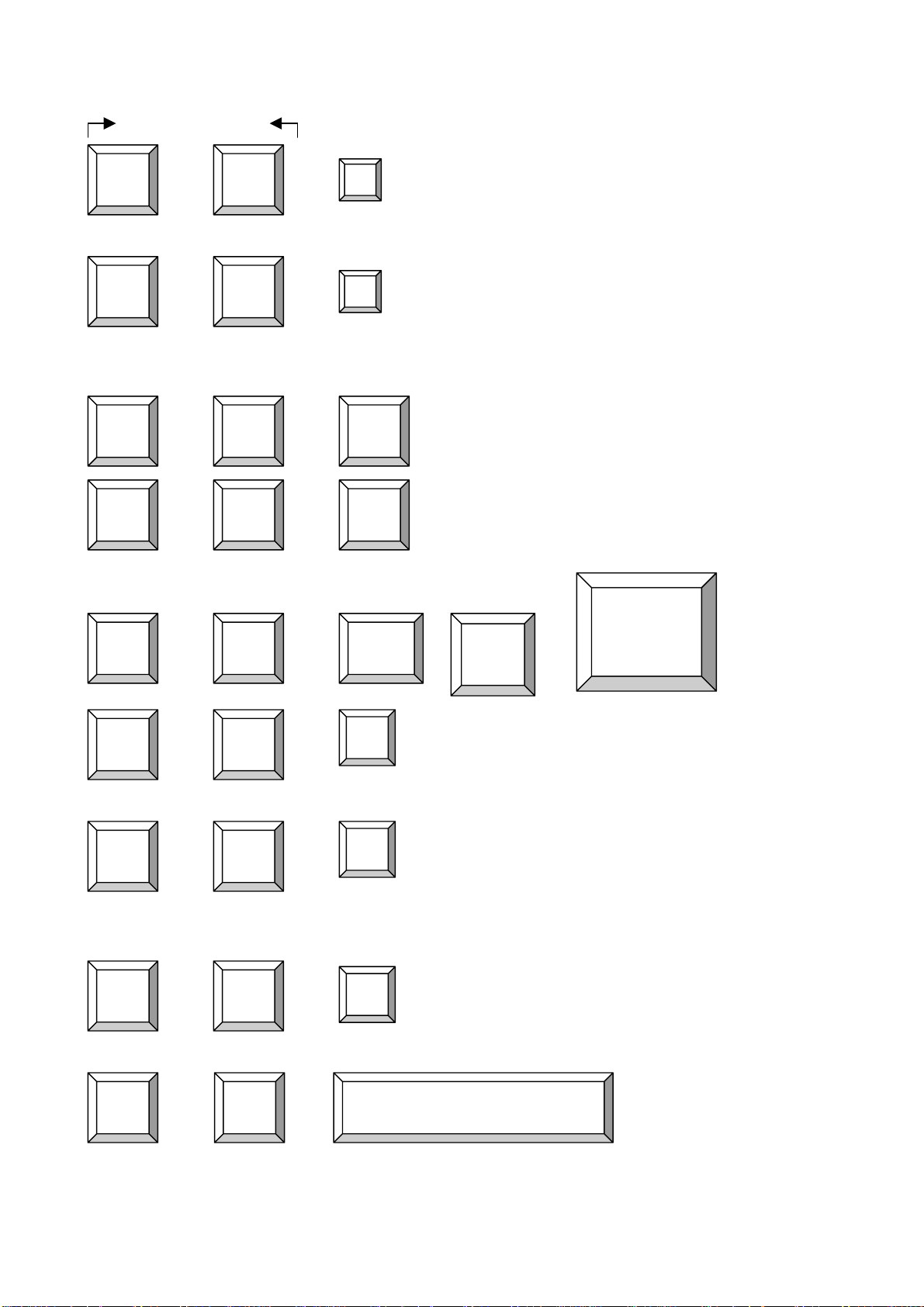
Below are the different hot key commands:
within 2 seconds
Scroll
+ + = Previous Power On Channel (PC is Power On)
Lock
Scroll
+ + = Next Power On Channel (PC is Power On)
Lock
(Note: You also could press “up arrow key” or “down arrow
Scroll
+ + = Previous Bank (PC is power on)
Lock
Scroll
Lock
Scroll
Lock
Scroll
Lock
↑
↓
key” longer time to speed up selecting the destination
port)
Page
Up
Scroll
+ + + + = Next Bank (PC is power on)
Lock
To select PC port:
Scroll
+ +
Lock
Scroll
Lock
(Note: The default Beeper function is ON and beeper
Scroll
Lock
To get out of Auto Scan Mode, Press any key or SPACE bar.
Scroll
Lock
Scroll
Lock
Scroll
+ + = Beeper
Lock
Scroll
+ + = Auto Scan (Note: This function is just for power on PC
Lock
Page
Down
Bank
1~8
B
S
Port No.
1~4 (4 port)
Port No
0 or 1
control is only for available for Scan Mode )
PORT )
1~8 (8 port)
1~16 (16 port)
Scroll
Lock
(Note: Not including password)
Scroll
+ + = OSD setting back to factory default value
Lock
R
Scroll
Lock
Scroll
+ + = On Screen Display Menu
Lock
Space Bar
13
Page 15

Example:
A. To access a computer attached to Port 4 of the third Bank. You can press through hot key as below:
Scroll lock + Scroll lock + 3 + 04
B. To access a computer attached from Bank 3 to Bank 4, You can press through hot key as below:
Scroll lock + Scroll lock + Page Down
Note:
Bank no. and Port no. selection must be made using the numeric keys on the keyboard.
Numeric keys on the keypad are not available as a hot key command.
Daisy Chain Connection Diagram
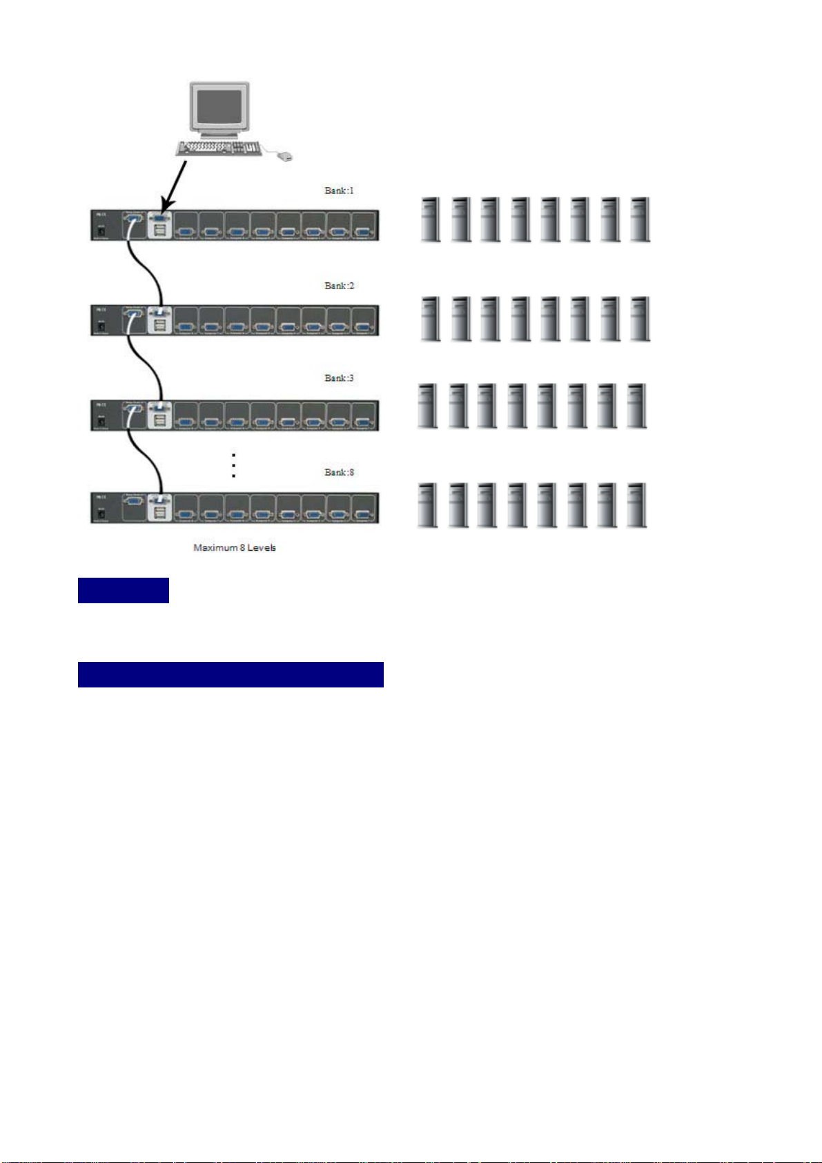
Please use the attached 3 feet VGA daisy chain Cable Kit to daisy chain the KVM
Switch and plug-in Power Adapter (12V 1A) into every KVM switch before daisy
chaining other KVM switch.
A. Connect Keyboard, Mouse and Monitor to the console port (silver color block) of bank 1
KVM switch.
B. Use one end of daisy chain Cable Kit to connect the daisy chain port of bank 1 and the
other end for the console port (silver color block) of bank 2 KVM switch.
C. Please repeat item B to daisy chain more bank as you want. But, the maximum daisy
chain bank is eight levels.
14
Page 16
Hot Plug
The USB KVM Switch supports “Hot Plug“ function for easy addition or removal of PCs.
On Screen Display Operation
On Screen Display provides a menu driven interface to handle a computer switching
process, to name a PC name or server name, to set up the password/window display time
and to search PC port name if you don’t remember it.
Note: When using the keyboard arrow key to move the cursor, the keypad arrow key (Up,
Down, Right, Left) is unable to work at this menu.
When you pop up the OSD menu window through the hot key, you will see the “MAIN
CONTROLS” window on your monitor as below. There are two ways, keyboard and mouse,
to operate the on screen display.
Keyboard Operating: In MAIN CONTROLS window, use the Up “©” or the Down ”ª” Key
to select a category and press Enter”” Key to get into designated option. Pressing “F1”
Key brings up HELP window and Esc key to exit.
Mouse Operating: You may also simply use mouse, twice clicking left button, to choose a
category. Clicking “?” will bring up HELP window and click “X” for exiting.
15
Page 17

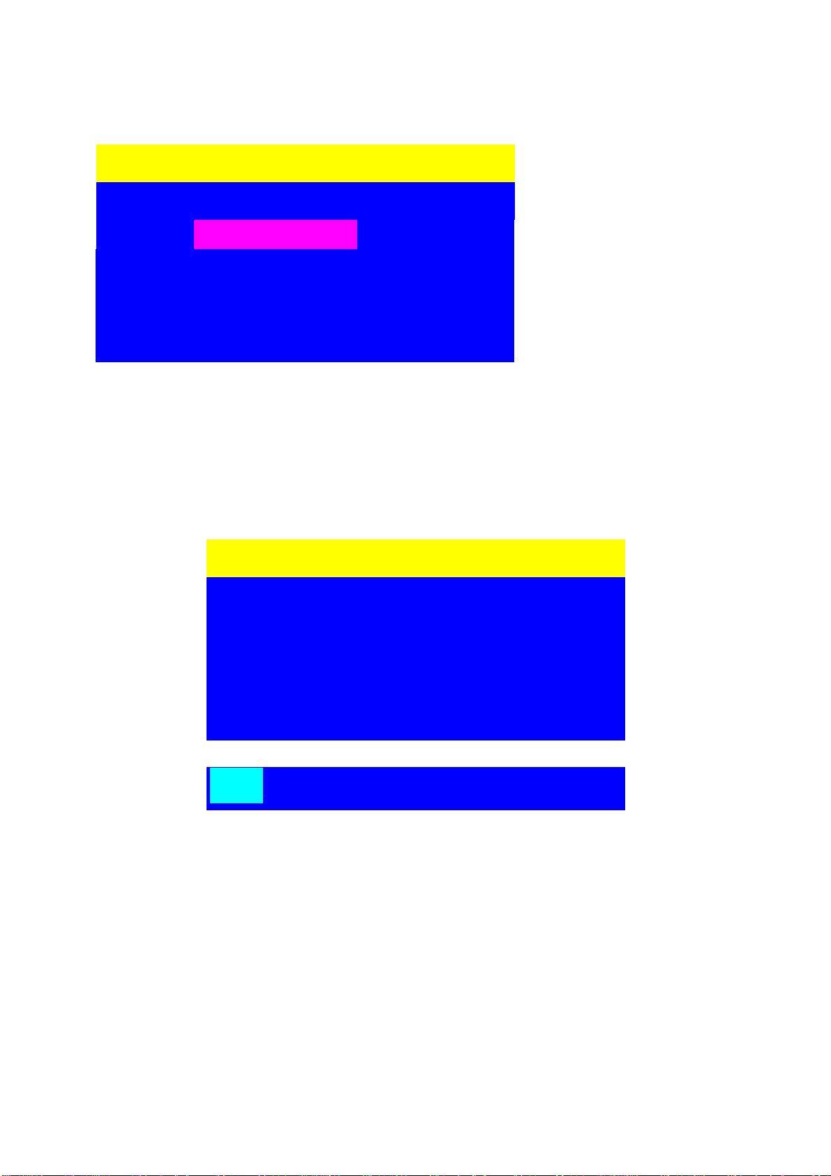
Once you use keyboard or mouse to move the highlight bar cursor to “ PORTNAME “ to press
[Enter] key or double clicks “ PORTNAME “ to activate “ PORTNAME ” window. The other items
like “ LANGUAGE ”, “ TIMEVIEW “, “ SECURITY “, “ FINDPORT “, “ PASSWORD “, and
“ CONSOLE “ need be activated in the same way.
MAIN CONTROLS ?X
ENTER A CHOICE :
01 LANGUAGE
02 PORTNAME
03 TIMEVIEW
04 SECURITY
05 FINDPORT
06 PASSWORD
07 CONSOLE
PORTNAME OSD Window :
a. The 1
PORTNAME ?X
BANK 1
01 SYSTEM 01
02
03
04
05
06
07
08
09
Using the Up key “© “ or the Down key “ª“ to select port for destination PC name. After you
☼ SYSTEM 02
SYSTEM 03
SYSTEM 04
SYSTEM 05
SYSTEM 06
SYSTEM 07
SYSTEM 08
☼SYSTEM 09
b. The 2
system name list. You will find
the system number list from 01
to 04 (if the current box is 4 port)
or from 01 to 08 (if the current
box no. is 8 port) or from 01 to 16
(if the current box no. is 16 port).
You can define your PC name in
maximum 10 characters. The
factory default of 16 port KVM
switch PC name is from
“SYSTEM 01”, “SYSTEM 02” ,…,
“SYSTEM 16” and 8 port KVM
switch is from “SYSTEM 01”,
“SYSTEM 02”,…, “SYSTEM 08”.
Besides, the sun symbol “☼
“near to the PC name represents
the PC system is powered on.
ST
line bar is Bank no.
nd
block is your PC
have selected the PC port already, you can either press the ENTER Key, or twice clicking the left
button of mouse to switch the PC port immediately. You can use mouse to click the triangle button,
which located at the right up side or the right down side, to scroll the menu. If there are more items
16
Page 18
than appear on the screen, the screen will scroll.
Use “ PgUp “ key or “ PgDn” key for selecting previous or next Bank no. (or Box No.)
PORTNAME ?X
Press “INS” key or click the
BANK 1
☼
YSTEM
1
02 SYSTEM 02
03 SYSTEM 03
04 SYSTEM 04
HELP OSD Window :
Please operate the options in HELP window by using Esc, Enter, Insert, arrow, and Page
Up/Page Down keys on your keyboard.
HELP ?X
ESC : QUIT
ENTER : COMPLETE
INSERT : EDIT
© / ª / ¨ / § : SELECT
PaUp / PaDn : BANK SELECT
right button of mouse for
editing PC name. To u s e
“ Tab “ key to select items
like BANK, TIMEVIEW,
SECURITY, CONSOLE,
FIND PORT…. etc.
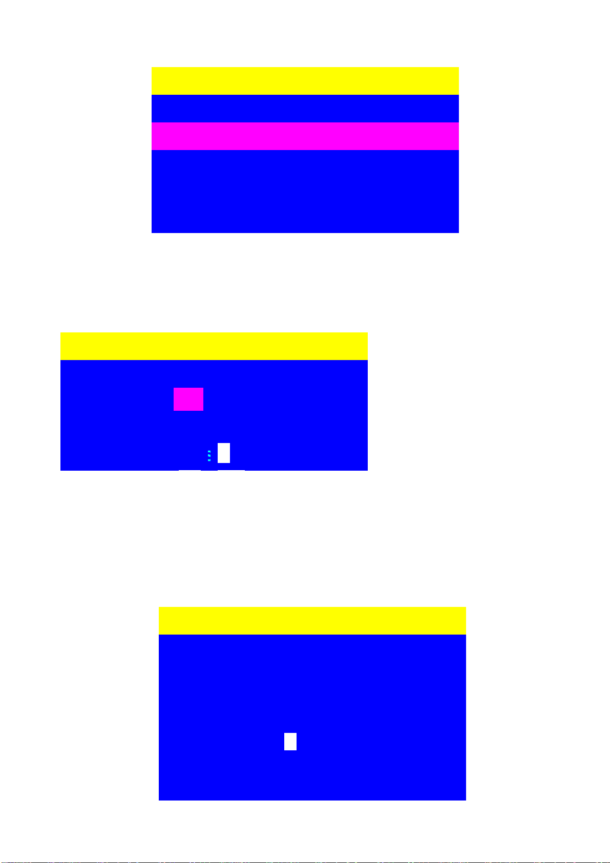
LANGUAGE OSD Window: MULTILINGUAL OSD
To use Keyboard: Press © / ª to choose a language and press ENTER to save.
To use Mouse: Move mouse and click the left button to choose a language, and click left
101
key again to save.
☼ SYSTEM 01
17
Page 19
_
_
_
LANGUAGE ?X
After finishing editing, please press “Enter “key for saving information.
TIMEVIEW OSD Window:
To use "©" and "ª" key on keyboard or press the “INS” key, or click the right button of
mouse to select and modify OSD and SCAN TIME.
TIMEVIEW ?X
OSD TIME : SEC
CHOOSE A LANGUAGE :
01 ENGLISH
a. The “OSD: 10 SEC” means
that the OSD windows
display or PC system name
exists 10 sec. on your
0
0
SCAN TIME :
monitor. You can modify it
from 05 sec to 99 sec. The
factory default value is 10
sec...
b. The “SCAN TIME” means that scan interval from one PC port to next PC port. The
default SCAN time is 10 sec and the maximum scan time is 99 sec.
SECURITY OSD Window:
The “CHANGE PASSWORD” is for user to avoid all PC systems to be intruded by the other
person. The default password is 8 digits “ 00000000 “.
SECURITY ?X
ENTER PASSWORD
_ _ _ _ _ _ _
ENTER NEW PASSWORD
_ _ _ _ _ _ _
RETYPE NEW PASSWORD
_ _ _ _ _ _ _
18
Page 20

There is a “SECURITY” window shows out when you select this category in MAIN
CONTROLS window. The maximum password is eight digits and there are three lines
“ENTER PASSWORD”, “ENTER NEW PASSWORD” and “RETYPE NEW PASSWORD” in
the window. Please follow the steps as below to modify the password.
1. First of all, you need to key-in the factory default password “00000000” in password
line and press the “Enter” key.
2. Then, enter the new password you wish in next line and press the “Enter” key.
3. Retype the new password in bottom line again and press the “Enter” key for
confirming your typed password is matched or not.
4. If the retyped new password has matched to the entering new password, the OSD
will jump back to MAIN CONTROLS window directly.
SECURITY ?X
CONSOLE OSD Window :
The “ CONSOLE ENABLE/DISABLE “ means to manage the console of KVM switch. If you
select “ CONSOLE ENABLE “, it means that any user can use the console. If you select
“ CONSOLE DISABLE “(factory default ENABLE state), it means that any user will not be
allowed to use the console unless you enter the password. When you enter the password
already and pass the KVM switch authentication, the CONSOLE will be set to ENABLE.
After you finish using KVM switch, please don’t forget to set up CONSOLE ENABLE state
to DISABLE state.
ENTER PASSWORD
••••••••
ENTER NEW PASSWORD
••••••••
RETYPE NEW PASSWORD
••••••••
CONSOLE ?X
ENABLE
DISABLE
19
Page 21

FINDPORT OSD Window :
The “FINDPORT“ option helps you to find the PC system, the name you defined in
PORTNAME function, by KVM switch. Key-in PC system name and press ENTER, it will
search the matching PC system and given the message for searching result.
FINDPORT ?X
ENTER NAME : _ _ _ _ _ _ _ _ _ _
Example:
a. When you key-in “SYSTEM 01” and press ENTER, if there is matching PC
systems were found by KVM switch, then the window will show the PC system
name “SYSTEM 01” and which BANK it belongs to. Besides, you also could
key-in wild card “ * “ and combine the other characters from A~Z and 0~9 to
search all of system name lists matched the same format .
FINDPORT ?X
BANK : 1
b. If there is no particular PC system name were found, the window will show
“PORTNAME NO FOUND!” message instead.
FINDPORT ?X
BANK : 1
PORTNAME NO FOUND !
To use “ PgUp “ key or “ PgDn” key for selecting previous or next Bank (or Box), then
the window will show matching PC system name or PORTNAME NO FOUND
message at other BANK (or Box).
20
Page 22

W
hen you finish the set up of PC name and get out of OSD setting mode, you will find the
PC name showed at the up-left corner of monitor. Now, you can use ESC key to clear the
message right away if you don’t need it.
Troubleshooting
Ensure that all cables are well seated. Label all of cables with the number for each
respective computer to avoid confusion.
IBM PC or Compatible:
Keyboard or mouse dose not work or not be compatible with the PC, please make sure
the keyboard or mouse works when directly plug into the computer. If the problem
persists, please try another keyboard or mouse.
Mouse doesn’t work in Auto Scan mode, you can press any key on the keyboard or the
front button on the face plate for returning standard mode and then use the Keyboard
or Mouse again.
When USB KVM switch is in Auto Scan mode, there are only VGA monitor display and
CPU alternately ( but the USB Hub is not switched in auto scan mode ). After you
press any key, the PC port will be selected at the same time, as you see the current
PC Screen.
If your motherboard BIOS is unable to be upgraded to new BIOS, you may need boot
this PC individually and the console port need be switched to this PC before you power
on this PC.
The recommended VGA cable distance is 5 meters maximum without ghosting and
degradation. Normally, the cable length is based on driver capacity of your VGA card.
Ensure that all cables are well seated. Label all of cables with the number for each
respective computer to avoid confusion.
The maximum keyboard or mouse cable is 5 meters feet maximum.
When you use Japanese windows OS with 106 key keyboard, there are some special
keys like “¥” need 106 key driver (Microsoft native driver in O.S. CD-ROM). Please
follow procedures below and click the mouse to add new driver.
Win98/SE/ME:
control panel → Add new hardware → Next → Next → Select
"No, the device isn't in the list" → Select →"No, I want to select the hardware from a list" →
Select keyboard → Select standard keyboard → Select (日本語) Japanese 106 key
keyboard → Reboot PC
21
Page 23

Win2000:
Control panel → System → Hardware → Device manager → Keyboards → Standard
keyboard → Click mouse right key → Properties → Driver → Update driver → Display a list
of the known drivers → For this device so that I can choose a specific driver → Standard
keyboard → Standard (日本語)Japanese 106 key keyboard → Reboot PC
WinNT:
Control panel → Keyboard → General → Change → Show all devices → Standard(日本語)
Japanese 106 key keyboard → Reboot PC
WinXP:
Control panel → System → Hardware → Device manager → Keyboards → Standard
keyboard → Click mouse right key → driver → Update driver → Install from a list or specific
location (advanced) → Don't search. I will choose the driver to install → Deselect show
compatible hardware → Standard keyboard → Standard(日本語)Japanese 106 key
keyboard → Reboot PC
CERTIFICATIONS
FCC
This equipment has been tested and found to comply with Part 15 of the FCC Rules.
Operation is subject to the following two conditions:
(1) This device may not cause harmful interference
(2) This device must accept any interference received. Including interference that may cause undesired
operation.
CE – Certificate
This equipment is in compliance with the requirements of the following regulations: EN 55
022: CLASS B
22
Page 24
23
BMN006810A00
 Loading...