

Eusonar Praktik 6 Pro 2 User Manual

1
Table of contents
INTRODUCTION...........................................................................................................................2
TECHNICAL SPECIFICATIONS OF THE SONAR .................................................................... 4
FIRST AQUANTANCE WITH THE SONAR……………………………………………………4
Sensor-converter and battery compartment………………………………………………. ………5
Unit control…………………………………………………………………………………..……7
Sonar screen……………………………………………………………………………………….9
OPERATION ORDER OF SONAR……………………………………………………..………11
SONAR OPTION MENU………………………………………...……………………………...13
Information display modes……………………………………………………………………….14
FISH ID…………………………………………………………………………………..………14
Pro……………………………………………………………………………………..…………17
Flasher……………………………………………………………………………………..……..18
Depth gauge…………………………………………………………………………………..….19
Fleet water……………………………………………………………………………………..…20
Demo…………………………………………………………………………………………..…20
Info…………………………………………………………………………………………….....21
Ruling of a screen…………………………………………………………………………….…..22
ZOOM……………………………………………………………………………………………22
NOF…………………………………………………………………………………………...…24
ADJUSTEMENTS…………………………………………………………………………….....25
Near-bottom thickness…………………………………………………………………………...25
"WINTER/SUMMER" mode…………………………………………………………………….25
Dead end........................................................................................................................................26
Sound and fish identification.........................................................................................................27
GENERAL RECOMENDATIONS ............................................................................................. 27
COMMON TROUBLES AND REMEDIES ................................................................................ 32
WARRANTY ................................................................................................................................ 34
CONTACT OF SERVICE CENTRE ............................................................................................ 35

2
INTRODUCTION
History of fishing amounts to thousands of years. However, in reality each time the
fisherman faces the same challenges: how to find the fish and make it grab the bait. The sonar
cannot make the fish grab the bite, but it is able to solve the problem of finding this fish. You will
never catch the fish there where there is not any – and the sonar of “Praktik” company will help
you make this fact true in the literate sense of this word.
Operating principle of the “Praktik” soner is based on emission of ultra-sonic waves by the
transducer-converter into the water and subsequently receipt of the echo pulses reflected from the
bottom or other objects. The probing beam represents the cone, the top of which is the sensor,
normally located just below the water surface, and the basement is the bottom. When the ultrasonic
wave encounters some obstacle on its way, its part is reflected and comes back to the transducer-
converter which now operates as a receiver and converts the reflected ultra-sound into an electric
signal.
The microcomputer processes the electric signals and prints on the sonar screen the
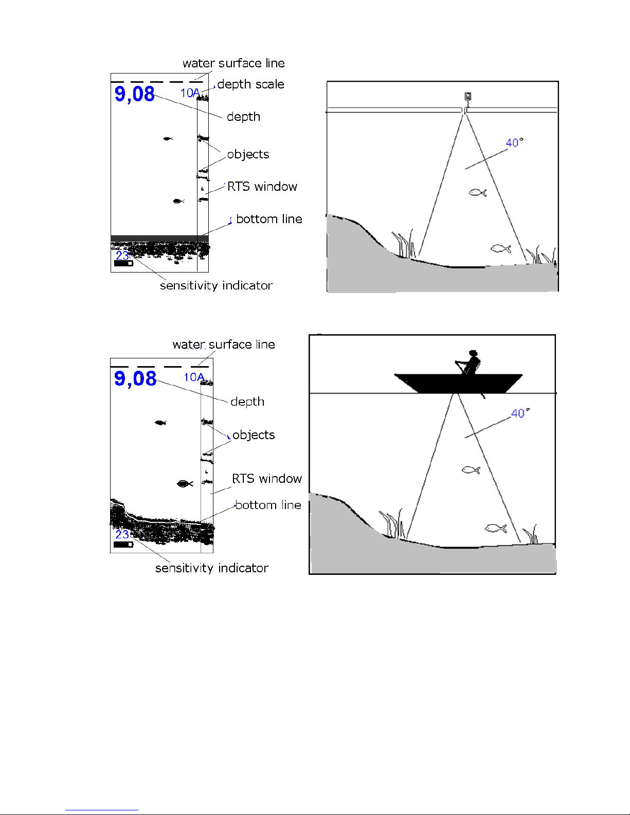
information on the topography of the bottom and the objects caught in the beam zone. The figures
above show typical pictures on the sonar screen and related information regarding these pictures
in the water depth of the reservoir in winter and summer.
Probing pulsing into the water is performed with frequency adjusted from two to four times
a second. The screen pattern shifts with the same speed. Data from the current echo-pulse will
appear in the right part of the screen and then moves to the left. The display top corresponds to the
water surface, whereas the lower part – to the lower part of the selected depth range.
It is very important to understand that the sonar does not reflect volume (3D) representation
of the water depth but only longitudinal section passing through the middle of the probing cone.
That/s what creates an illusion that all the objects detected by the beam are located under the
sensor.
3
Display pattern in winter Winter reservoir
Display pattern in summer Summer reservoir
Sonar models ER-6 Pro2 can reflect as processed information in the format easy for understanding,
as well as unprocessed information (“raw” one which is more difficult for understanding but it is
more informative than in the first case) With the assistance of MENU one can choose the most
suitable type of information representation. If a fish gets in the probing cone of the display mode,
of the processed information, this event will be recorded and the fish outline will show up on the

4
display mode of the processed information. Near-bottom structures will look like spots on the
bottom contour. One can understand from the bottom line width if the bottom is dense or muddy,
and guess its structure.
TECHNICAL SPECIFICATION OF THE SONAR
FIRST AQUANTANCE WITH THE SONAR
Model ER-6 Pro2 sonar design is made in two units: electronic and sensor-converter unit
with the battery compartment. The sensor-converter is connected with the electronic unit with
assistance of the cable 2 m long.
Setting functions
Amplification, automatic or manual selection of the depth scale,
identification of the fish, “winter-summer” mode, adjusting
“zoom”, dead zone, “flasher” mode, fleet water.
Measuring depth range, m
0,5–25,0 m (measurement accuracy ±1sm for depth 0.5-10m
and ±10sm for depth from 10-25m )
Probing angle, degree
40°
Display
monochromic, high-contrast, frost-resistant,
resolution128×64 points (5×3sm)
Temperature range, °С
from –15 to +40°C
Power supply
1 element АА (200 operation hours with frequency 2 Hz)
Electronic block size
100×72×23
Sensor-converter size
25×80
Unit weight
170g

5
The electronic unit represents the structural design with two control buttons, transparent
window and tightly closed cable not less than two meters long. The level of leak resistance is
compliant with IP 67 standards.
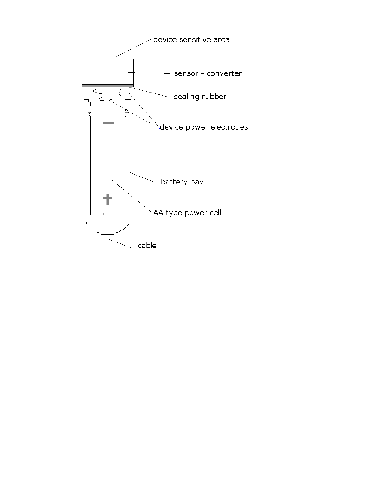
Sensor-converter and battery compartment
The sensor-converter works simultaneously as an acoustic wave emitter as a receiver
(microphone) of echo-signal objects reflected from the bottom. The sensor design is frost-
resistant, leak-proof (IP68). The sensor is screwed into the battery compartment. Pressurization of
the battery compartment is performed with assistance of the sealing silicone ring. When installing
the power supply unit АА it is necessary to observe polarity.
It is advisable to install he battery at home at a warm place. It will ensure avoidance of
appearance of the condensate water in the battery compartment. Take care of the sensor.
Unfortunately it does not float. It sinks and it is expensive. Besides, one should protect it from
severe blows over hard objects.
Under conditions of winter fishing it is desirable to lower the sensor below the underwater
ice edge to avoid appearance of false signals reflected from the vertical walls of the ice-hole.
To save the battery service life it is not recommended to leave the sensor-converter in frost:
when operating is must be wholly into the water, the temperature of which is always positive, and
when the sensor is not used – in a warm place under the clothes.
For correct depth measurement the sensible area of the sensor must be located strictly in
parallel to the water surface. It should be remembered that the bottom depth and other objects are
measured not relatively the water surface but to the sensor, that is why at its big depth the figures
shown by the sonar can differ considerably from the true ones.
The sonar is equipped with the special cable with the cover made of silicone resin,
connecting the electronic unit and the battery compartment with the sensor. This cable will remain
elastic even in the most severe frosts, with which an ordinary rubber cable will lose its elasticity
and can easily crack, thus losing its impermeability.
6
In the body of the device there are four fastening openings located along the body angles.
They are designated for fastening the cord and for installation the special furniture on the device
to fasten the sonar to the leg or the sleeve. The furniture is not included in the set.
There is a special bracket for the sensor in the delivery set. Its fastening to the boat is
performed with assistance of the clamp or other accessories. The sensor can be fastened on the
float as well. Fastening of the electric unit to the boat is possible with special holders for mobile
telephones.
Examples of uncomplicated appliances and furniture for the sonar fastening to the floating
craft are shown on our site www.rusonar.ru.
7
Unit control
There are two buttons to control the sonar. There functions are described below.
LEFT BUTTON
In operation mode
1. Switching between automatic and manual scale selection modes and “zoom” mode).
2. Illumination on/off (hold down for 5 sec)
In MENU mode:
Current MENU point value correction
Left button in operation mode serves to change over the sonar to one of three operation
modes: automatic scale selection (Auto Range), manual scale selection and “zoom” mode. If
automatic mode is chosen the current scale and “A” letter are reflected in the top right angle, and
if manual one–scale and “M” letter. In “zoom” mode scale is not reflected, instead the magnifier
with the figure mark will be output. If sensibility adjustment is performed it is possible to change
adjustment direction (increase or decrease) with the left button (single push).
If you hold the left button pushed long enough (around 5 sec) the screen illumination will be
switched on or off.
When the sonar is in MENU, the left button corrects MENU current point value.

8
RIGHT BUTTON
In operation mode
1. Sonar switch-off (single push)
2. Change-over to MENU (double push)
3. Durable push to adjust sensibility
In MENU mode:
Change-over between MENU points and exit to operation mode
Right button serves to switch on and off the sonar and also to exit MENU and changeover
between its points. The sonar switch-off is performed via single pushing, with this the countdown
figures will appear on the display: 3–2–1. If you push the right button once again during the
countdown, the sonar will change over to MENU mode. To adjust the sonar sensibility in the
operation mode it is necessary to hold the right button pushed, with this the vertical strip
“thermometer” will appear in the left side of the indicator that show change of sensibility. To
change the adjustment direction it is necessary to hold temporarily the left button.
After change over to MENU the right button goes through various MENU items. The sonar
will come back to the operation mode after finishing searching all items.
9
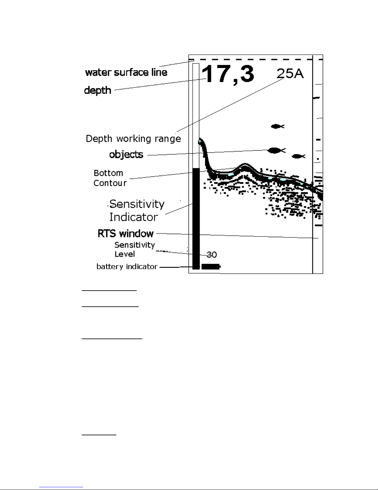
Sonar display
Water surface line is shown in the form of the running dotted line.
Digital depth value is updated two-four times a second with resolution ±1sm for depths to
10m and resolution ±10sm for depths from 10 to 25 meters.
Sensitivity indicator visual displays if the right button is pushed and held. Vertical strip
“thermometer” shows sensitivity rude value, and the figure under the depth value shows the exact
sensitivity value. Sensitivity indicator disappears from the screen when releasing the right button.
Sensitivity can be adjusted within the range from 0 to 28 units. Value 12 units is set automatically.
Adjustment direction (increase of decrease) can be changed if you push the left button for the short
moment during adjustment..
Soil density conventionally shows power of the echo-signal reflected from the bottom and
can vary from 0 to 20 units. The higher is the number, the more powerful the signal from the

10
bottom (or the high density of the soil), and vice versa, a small number will say that from the
bottom signal is weak (low soil density). With the same reflecting capacity of the bottom, the
density will be reduced with respect to the depth increase because with this the signal becomes
weaker.
Operation range shows what maximum depth can be reflected on the screen at a particular
moment. If there is letter A at the figure, it means that the device is in automatic scale selection
mode and it will be automatically changed when leaving beyond definite limits of the bottom
depth. If there is letter M, it means that the unit operates in the manual scale selection mode: it will
not change even if the bottom approaches considerably to the upper part of the screen or goes
beyond its lower limit. Scale value for this mode is set via MENU. At last, the magnifier symbol
with the figure instead of the operation range indicator informs that the sonar is in mode “zoom”
(it will be described separately).
RTS-window – this is the screen area which reflects all registered echo-signals from the
bottom and other objects without any processing. In the main area of the screen the data processed
by the computer
(bottom line, near-bottom structures and fish symbols) is displayed.
Battery indicator shows the capacity of battery at the given time. It has 12 gradations. If
the last level occurs, the device can operate for several hours, but when restarting the message
“Battery is low” can appear on the display. More accurate battery status can be assessed if you go
to the Info mode, where the battery voltage is specified in volts. The limit value of the battery
voltage at which the sonar can work effectively is 0.85W.
OPERATION ORDER OF SONAR
Total operation order:
1. Turn off (counter clockwise) the sensor from the battery compartment. Insert a new battery
into the battery compartment observing polarity (“plus” must be at the bottom). Put the sensor in

11
its place revolving clockwise. It is enough to turn the sensor tight manually for pressurization. Do
not use with this the tool type of pliers.
2. Press the right button. The message greeting will appear of the screen:
“Praktik ER-6 Pro2 Lucky fishing”,
which further on will be moved to the left on the screen.
ATTENTION!
If the sensor is not screwed tightly enough in the battery compartment, then the on the
display will appear a warning message “SENSOR?”. The same message will appear if a
cable is damaged.
After installing the batteries, it is recommended that you restart the device, so it will return
to the factory settings. Press and hold the left button and then press the right button for 1-
2 seconds. The message “OK” will appear on the display, and the following factory
settings will be installed:
– scaling: image auto-scaling mode;
– amplification: 12 (from 28 units);
– screen scale for its manual selection mode: 7 meters;
– screen view: fish definition mode and window RTS;
– fish identification and sound: are on;
– near bottom layer depth in “zoom” mode: 2 meters
- dead zone: 05-1 meter
“Winter/Summer” mode: summer
Resetting can be made in the different time, but only when the device is turned off.
Note: if battery was inserted earlier, then it is necessary to press the right button once to turn on
the sonar. All previously installed modes by doing so are saved.
3. Put the sensor into the water with assistance of the cable. It is desirable to put the sensor
fully below the ice edge in winter to avoid extreme cooling of the battery and offset of noise signal

12
of the ice-hole. After the sensor contacts the water the appearance of micro-bubbles on its sensible
surface is possible which can strongly dissipate registering signals and thus reduce sensibility and
mispresent the true picture. It is required to remove the bubbles plunging the sensor for several
times or rub the sensor surface with your fingers after plunging it into the water.
4. If the sensor is immobile the bottom on the screen will be imaged in the shape of even
line. With small depth and the bottom with good reflecting capacity in consequence of the multiple
re-reflecting signal from the bottom and the water surface appearance of several “bottom” lines
parallel to the true bottom and laying on the depths divisible by the true bottom depth is possible.
If the fish is caught in the beam cone the sound signal will go off, and the fish sign on the
corresponding depth will appear.
5. If the sensor is fixed on the moving boat, then the configuration of the bottom and the
near-bottom structures under the boat will be picked in. if the fish swims through the beam cone
the signal will ring out and the mark on the relative depth on the screen will appear.
6. To switch off the device it is necessary to press the right button one-time. Upon completion
of the countdown the sonar will be switched off.
7. If the sonar is in operation mode for more than four hours and none of the buttons is not
pushed for this time the sonar will be switched off automatically.
8. For durable switch off of the sonar it is recommended to de-energize it fully removing the
battery because it consumes energy even if it is switched off. Power consumption is miserable,
but low-quality batteries with this discharging current may increase in size and may damage the
battery compartment.
ATTENTION! Don’t leave the battery for the long period of time (inter-season) in the
battery compartment.
 Loading...