

Eurtotherm 2216e, 2208e, 2204e Engineering Handbook

2200e
Engineering
Handbook
2200e Series Controllers
HA029989/3
July 2014


2200e Series Installation and Configuration Handbook Contents
2200e Series Controllers
Installation and Configuration Handbook
Models 2216e, 2208e and 2204e
Contents
1 Installation ................................................................................................................................................ 1-1
1.1 Instrument Layouts ......................................................................................................................................... 1-1
1.1.1 Outline Dimensions ................................................................................................................................................................................... 1-2
1.1.2 Recommended minimum spacing of controllers ............................................................................................................................. 1-2
1.2 Introduction.................................................................................................................................................... 1-3
1.2.1 Controller labels ......................................................................................................................................................................................... 1-3
1.3 Mechanical Installation ................................................................................................................................... 1-3
1.3.1 Unplugging and plugging-in the controller ........................................................................................................................................ 1-3
1.4 Wiring ............................................................................................................................................................. 1-4
1.4.1 Wire Sizes ..................................................................................................................................................................................................... 1-5
1.4.2 Sensor input connections ........................................................................................................................................................................ 1-6
1.4.3 Outputs 1 and 2 connections ................................................................................................................................................................. 1-6
1.5 PDS Modes ...................................................................................................................................................... 1-7
1.6 Snubbers ......................................................................................................................................................... 1-7
1.7 Typical single loop wiring diagram ................................................................................................................. 1-7
1.8 Logic Drive Fan Out ........................................................................................................................................ 1-8
1.9 EIA232/485/422 Communication connections .................................................................................................. 1-8
1.9.1 Wiring of EIA-485 serial communication links................................................................................................................................... 1-9
1.10 DeviceNet® Wiring to Series 2200e Controllers ............................................................................................ 1-10
1.10.1 DeviceNet Terminal Functions ............................................................................................................................................................. 1-10
1.10.2 Wiring Interconnections for DeviceNet Communications ........................................................................................................... 1-10
2 Operation .................................................................................................................................................. 2-1
2.1 Front Panel Layout .......................................................................................................................................... 2-1
2.2 Getting Started ............................................................................................................................................... 2-3
2.2.1 To View The Process Value and Setpoint ........................................................................................................................................... 2-3
2.2.2 To Adjust The Setpoint ............................................................................................................................................................................. 2-3
2.2.3 To View The Display Units ....................................................................................................................................................................... 2-3
2.2.4 Use Of The “SCROLL” Button ........................................................................................................................................................ 2-4
2.2.5 Use Of The ‘PAGE’ Button ............................................................................................................................................................... 2-4
2.3 Parameter Lists ............................................................................................................................................... 2-5
2.4 Manual or Automatic Control ......................................................................................................................... 2-6
2.4.1 To Select Auto/Manual Operation ........................................................................................................................................................ 2-6
2.4.2 To Manually Adjust Output Power........................................................................................................................................................ 2-6
2.5 Selecting SETPOINT 1 OR SETPOINT 2 ............................................................................................................. 2-7
2.5.1 To Select Setpoint 1 orSetpoint 2 ......................................................................................................................................................... 2-7
2.6 Ramp Dwell Function ...................................................................................................................................... 2-7
2.6.1 To Set up a Ramp/Time Program .......................................................................................................................................................... 2-8
2.6.2 To Run the Program .................................................................................................................................................................................. 2-8
2.6.3 Power Failure During Program Run ...................................................................................................................................................... 2-8
2.7 Location of Parameters - Block Diagram ......................................................................................................... 2-9
2.8 Navigation Diagram ...................................................................................................................................... 2-10
2.9 Parameter Tables .......................................................................................................................................... 2-11
2.9.1 HOME Display ............................................................................................................................................................................................ 2-11
2.9.2 Alarm List .................................................................................................................................................................................................... 2-11
2.9.3 Autotune List ............................................................................................................................................................................................. 2-12
2.9.4 PID List ......................................................................................................................................................................................................... 2-12
2.9.5 Setpoint List ............................................................................................................................................................................................... 2-12
2.9.6 Input List ..................................................................................................................................................................................................... 2-13
2.9.7 On/Off List.................................................................................................................................................................................................. 2-13
2.9.8 Output List ................................................................................................................................................................................................. 2-13
2.9.9 Communications List ............................................................................................................................................................................... 2-14
2.9.10 Access List .................................................................................................................................................................................................. 2-14
2.10 Alarms .......................................................................................................................................................... 2-15
2.10.1 Types of Alarm Used in the 2200 ........................................................................................................................................................ 2-15
2.11 Alarm Relay Output ...................................................................................................................................... 2-16
2.11.1 Setting Alarm Levels ................................................................................................................................................................................ 2-16
2.11.2 Alarm Indication and Acknowledgement.......................................................................................................................................... 2-17
2.11.3 Diagnostic Alarms .................................................................................................................................................................................... 2-18
i Part No. HA029989 Issue 3 CN31940 July-14

Contents 2200e Series Installation and Configuration Handbook
3 Access Levels ............................................................................................................................................ 3-1
3.1 The Different Access Levels ............................................................................................................................. 3-1
3.2 Selecting An Access Level ................................................................................................................................ 3-1
3.2.1 Access list header ....................................................................................................................................................................................... 3-1
3.2.2 Password entry ............................................................................................................................................................................................ 3-1
3.2.3 Level Selection ............................................................................................................................................................................................. 3-2
3.2.4 Configuration password ............................................................................................................................................................................ 3-2
3.2.5 Configuration level ..................................................................................................................................................................................... 3-2
3.2.6 To Return to Operator Level ................................................................................................................................................................... 3-2
3.3 Edit Level ........................................................................................................................................................ 3-3
3.3.1 To Set Operator Access to a Parameter .............................................................................................................................................. 3-3
3.3.2 To Hide or Reveal a Complete List ........................................................................................................................................................ 3-3
3.3.3 To Promote a Parameter .......................................................................................................................................................................... 3-3
4 Tuning....................................................................................................................................................... 4-1
4.1 What Is Tuning?............................................................................................................................................... 4-1
4.2 Automatic Tuning ............................................................................................................................................ 4-1
4.2.1 Heating and Cooling Output Cycle Times ........................................................................................................................................... 4-1
4.3 How To Tune ................................................................................................................................................... 4-2
4.3.1 Typical automatic tuning cycle ............................................................................................................................................................... 4-2
4.3.2 Calculation of the cutback values .......................................................................................................................................................... 4-2
4.4 Manual Tuning ................................................................................................................................................ 4-3
4.4.1 Setting the cutback values ....................................................................................................................................................................... 4-3
4.4.2 Integrating Action and Manual Reset ................................................................................................................................................... 4-4
4.4.3 Automatic Droop Compensation (Adc) ............................................................................................................................................... 4-4
5 Configuration ........................................................................................................................................... 5-1
5.1 To Select Configuration Level .......................................................................................................................... 5-1
5.2 To Select a Configuration Parameter ............................................................................................................... 5-2
5.3 To Leave Configuration Level .......................................................................................................................... 5-2
5.4 Steps Involved In Configuring A Controller ..................................................................................................... 5-2
5.5 Navigation Diagram (PART A).......................................................................................................................... 5-3
5.6 Configuration Parameter Tables ...................................................................................................................... 5-5
5.6.1 Instrument Configuration ......................................................................................................................................................................... 5-5
5.6.2 Input Configuration .................................................................................................................................................................................... 5-6
5.6.3 Calibration Configuration ......................................................................................................................................................................... 5-6
5.6.4 Alarm Configuration .................................................................................................................................................................................. 5-7
5.6.5 Logic Inputs Configuration - 2208e and 2408e only. ....................................................................................................................... 5-7
5.6.6 AA Alarm Relay Configuration - 2208e and 2408e only ................................................................................................................. 5-8
5.6.7 Digital Communications Configuration ................................................................................................................................................ 5-8
5.6.8 Output 1 Configuration ............................................................................................................................................................................ 5-9
5.6.9 Output 2 Configuration ......................................................................................................................................................................... 5-10
5.6.10 Output 3 Configuration ......................................................................................................................................................................... 5-10
5.6.11 Output 4 Configuration ......................................................................................................................................................................... 5-10
5.6.12 Password Configuration ......................................................................................................................................................................... 5-10
5.6.13 Exit Configuration .................................................................................................................................................................................... 5-10
5.7 Configuration of Digital Communications ..................................................................................................... 5-11
5.7.1 To Configure the Function, and Baud Rate ..................................................................................................................................... 5-11
5.7.2 To Set Instrument Address ................................................................................................................................................................... 5-11
5.8 DeviceNet...................................................................................................................................................... 5-12
5.8.1 The EDS File ............................................................................................................................................................................................... 5-12
5.8.2 ODVA Compliance ................................................................................................................................................................................... 5-12
6 User Calibration ........................................................................................................................................ 6-1
6.1 What is the Purpose of User Calibration? ........................................................................................................ 6-1
6.2 User Calibration Enable ................................................................................................................................... 6-1
6.2.1 The User calibration configuration List ................................................................................................................................................ 6-1
6.3 Single Point Calibration ................................................................................................................................... 6-2
6.4 Two Point Calibration ...................................................................................................................................... 6-3
6.5 Calibration Points and Calibration Offsets ....................................................................................................... 6-3
7 Alarm Configuration ................................................................................................................................. 7-1
7.1 Definition Of Alarms And Events ..................................................................................................................... 7-1
7.1.1 Types of Alarms ........................................................................................................................................................................................... 7-1
7.2 Digital Output Functions ................................................................................................................................. 7-2
7.3 Step1 - To Configure the Four ‘Soft’ Alarms .................................................................................................... 7-3
7.4 Step 2 - To Attach an Alarm to A Physical Output ........................................................................................... 7-4
ii Part No. HA029989 Issue 3 July-14

2200e Series Installation and Configuration Handbook Contents
7.5 Step 3 - To Group Alarms on a Single Output ................................................................................................. 7-5
7.6 Step 4 - To Remove Alarms From An Output ................................................................................................... 7-5
8 Motorised Valve Control ........................................................................................................................... 8-1
8.1 Parameters For Motorised Valve Control ........................................................................................................ 8-1
8.2 Commissioning the Motorised Valve Controller .............................................................................................. 8-1
8.2.1 Adjusting the minimum on-time ‘Ont.H’............................................................................................................................................ 8-1
8.3 Motorised Valve Applications ......................................................................................................................... 8-2
8.3.1 Auto Tuning ................................................................................................................................................................................................. 8-2
8.3.2 Valve Positioner Set-up Table ................................................................................................................................................................ 8-2
9 Load Current Monitoring and Diagnostics ................................................................................................ 9-1
9.1 Load Current Monitoring and Diagnostics ....................................................................................................... 9-1
9.2 Example Wiring Diagram (For mode 1 & 2 operation) ..................................................................................... 9-2
9.3 Example Wiring Diagram (for mode 5 operation) ............................................................................................ 9-3
9.4 Operation ....................................................................................................................................................... 9-4
9.4.1 To Read Load Current (modes 2 and 5 only) .................................................................................................................................... 9-4
9.4.2 To Display Load Current Continuously in the Lower Readout (modes 2 and 5 only) ........................................................... 9-4
9.4.3 Display Modes ............................................................................................................................................................................................. 9-4
9.4.4 How Heater Alarms Are Displayed ........................................................................................................................................................ 9-5
9.5 To Set The Alarm Trip Levels .......................................................................................................................... 9-5
9.6 Relay Outputs ................................................................................................................................................. 9-6
9.7 To Configure PDS Load Current Diagnostics.................................................................................................... 9-6
9.7.1 To Configure the Logic Module for PDS modes 1 or 2 .................................................................................................................. 9-6
9.7.2 To configure Logic Input 1 for PDS (Mode 5 only) ......................................................................................................................... 9-7
9.8 To Configure Low and High Current Trip Alarms............................................................................................. 9-7
9.9 To Attach Soft Alarms To A Relay Output ....................................................................................................... 9-8
9.10 The Scaling Factor .......................................................................................................................................... 9-9
9.10.1 To Adjust The Scaling Factor .................................................................................................................................................................. 9-9
10 Retransmission .............................................................................................................................. 10-1
10.1 What is retransmission .................................................................................................................................. 10-1
10.2 To Configure Retransmission ........................................................................................................................ 10-1
10.3 To Scale Retransmitted Output Signals ......................................................................................................... 10-2
10.3.1 To Range Retransmitted Output OP ................................................................................................................................................. 10-2
10.3.2 To Range Retransmitted Setpoint SP or Process Variable PV ................................................................................................ 10-2
10.3.3 To Range Retransmitted Error Err .................................................................................................................................................. 10-2
11 Understanding the Order Code ..................................................................................................... 11-1
12 SAFETY and EMC Information ....................................................................................................... 12-1
12.1 Technical Specification ................................................................................................................................. 12-3
13 Supplement 2208e Instruments ..................................................................................................... 13-1
14 Index ............................................................................................................................................. 14-3
This product is cove red by one or more of the f ollowing US Patent s :
5,484,206 and 5,793,754; Additional patents pending.
PDS is a registered trademark of Eurotherm.
INSTANT ACCURACY™, SSRx Load Doct or™ and SSRx Enhanced Load Doc t or ™
are trademarks of Eurotherm
Symbols in Use In This Handbook
Tip
Useful information
Button Operation
Caution, (refer to the
accompanying documents)
!
Part No. HA029989 Issue 3 July-14 iii

2200e Series Installation and Configuration Handbook Installation
1 Installation
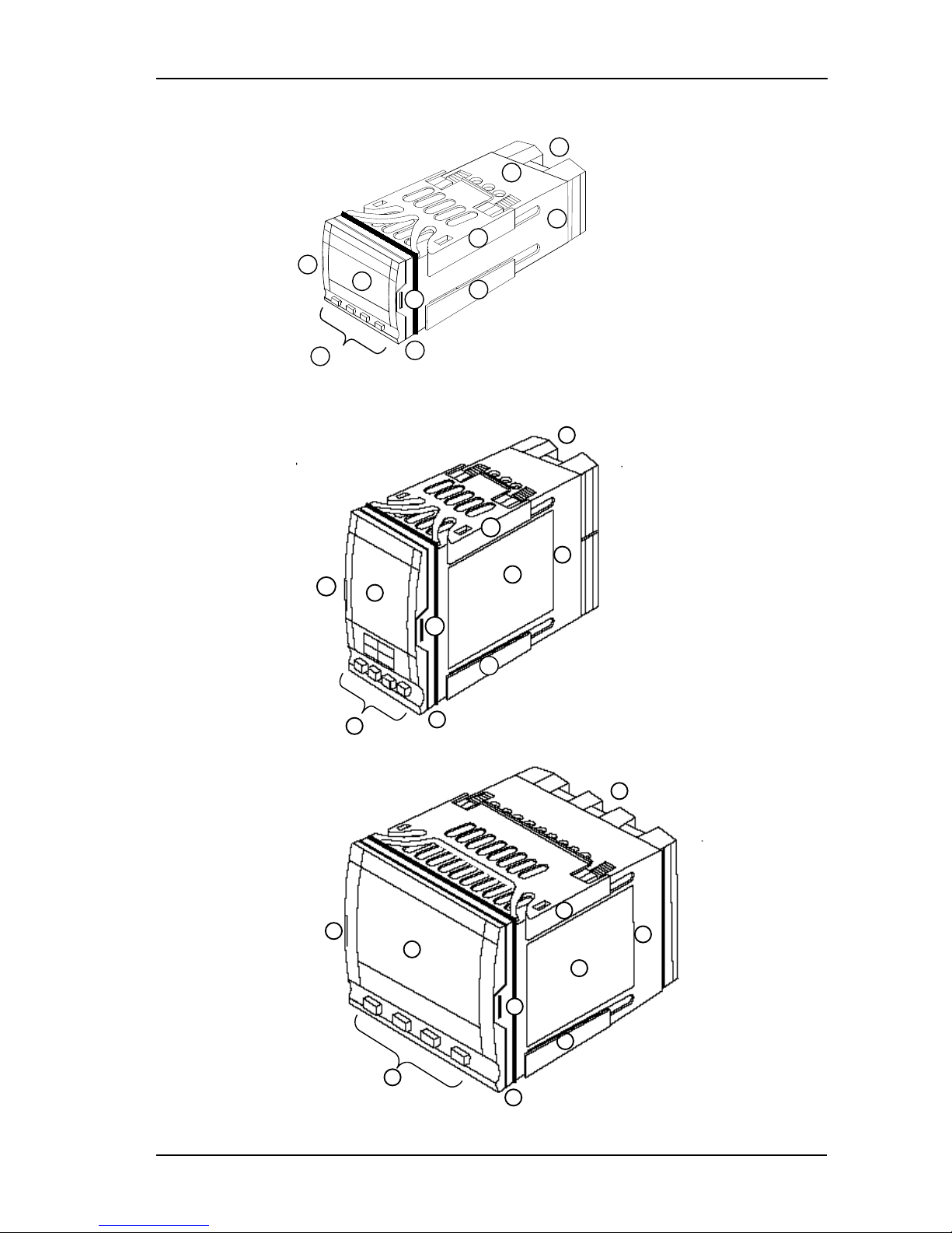
1.1 Instrument Layouts
Figure 1-1: 2216e 1/16 DIN Controller
Figure 1-2: 2208e 1/8 DIN Controller
Figure 1-3: 2204e 1/4 DIN Controller#
KEY
1. Display screen
2. Latching ears
3. Panel sealing gasket
4. Panel retaining clips
5. Label
6. Sleeve
7. Connection Terminals
8. Keypad
5
6
7
8
3
1
2 2 4
4
1
2
3
4
4
5
6
7
8
2
5 2 1 8 6 7 3 2 4
4
Part No. HA029989 Issue 3 July-14 1-1
Installation 2200e Series Installation and Configuration Handbook
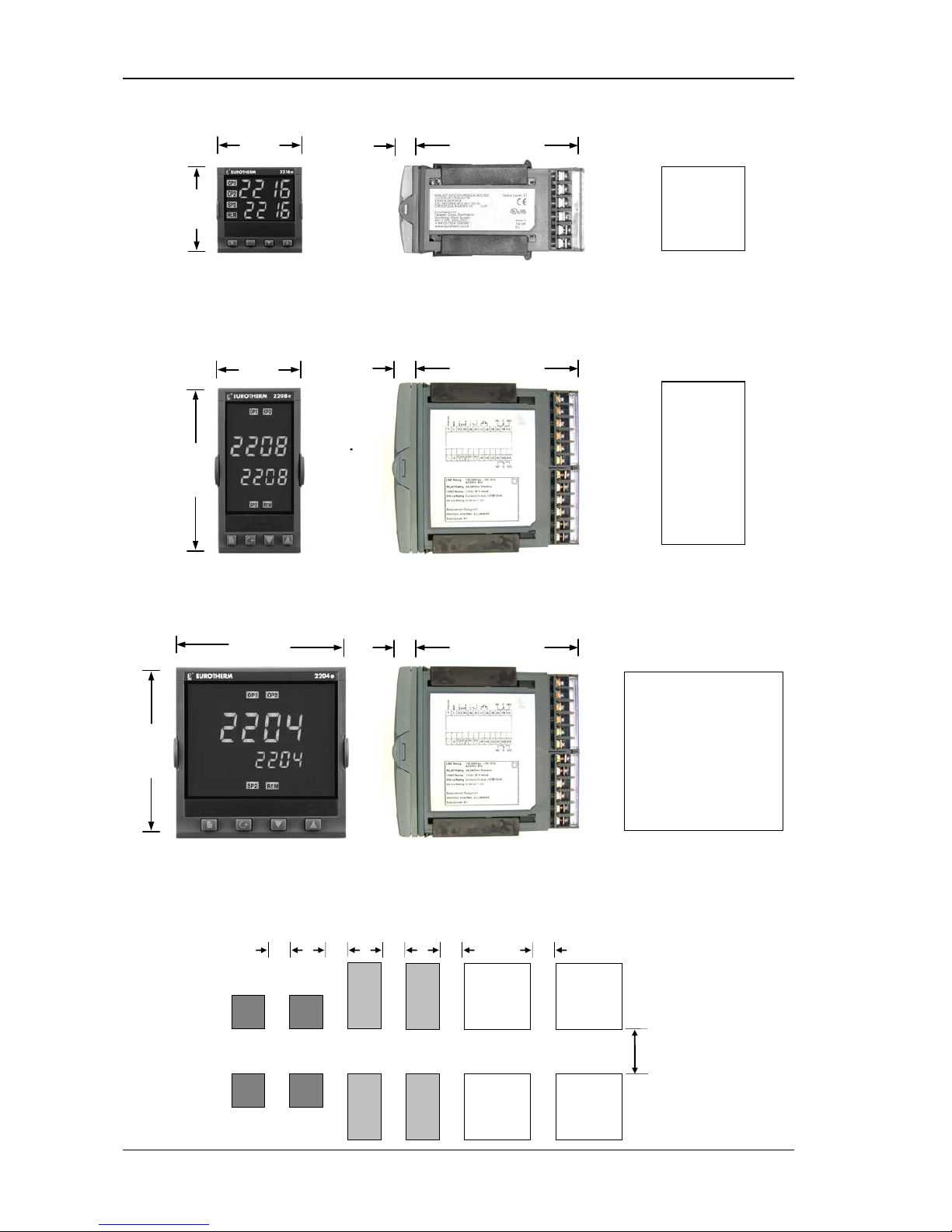
1.1.1 Outline Dimensions
Figure 1-4: 2216e Controller
Figure 1-5: 2208e Controller
Figure 1-6: 2204e Controller
The controller plugs into a plastic sleeve, which in turn fits into the panel cut-out.
1.1.2 Recommended minimum spacing of controllers
Panel cutout
45 x 45
-0 + 0.6 mm
1.77 x 1.77
-0 + 0.02
in
48mm
(1.89in)
48mm
(1.89in)
103mm (4.01in)
12.5mm
(0.5in)
103mm (4.01in)
12.5mm
(0.5in)
48mm
(1.89in)
96mm
(3.78in)
Panel cutout
45 x 92 mm
-0 + 0.6 -0 + 0.8
1.77 x 3.62 in
-0 + 0.02 -0 + 0.03
Panel cutout
92 x 92
-0 +0.8mm
3.62 x 3.62
-0 +0.03
in
103mm (4.01in)
12.5mm
(0.5in)
96mm
(3.78in)
96mm
(3.78in)
38mm
(1.5in)
X = 10mm (0.4in)
(Not to
scale
)
X X X X X
1-2 Part No. HA029989 Issue 3 July-14

2200e Series Installation and Configuration Handbook Installation
1.2 Introduction
The Models 2216e, 2208e and 2204e are precision temperature controllers with self tuning. They have a modular
hardware construction which provides two control outputs, alarm relays and one communications port. Two logic
inputs are provided as standard in 2208e and 2204e.
1.2.1 Controller labels
The labels on the sides of the controller identify the ordering code, the serial number, and the wiring connections.
Section 11, Understanding the Ordering Code explains the hardware and software configuration of your particular
controller.
1.3 Mechanical Installation
To install the controller
1. Cut the panel to the relevant hole size shown in Section 1.1.1.
2. Fit the IP65 sealing gasket behind the front bezel of the controller.
3. Insert the controller in its sleeve through the cut-out.
4. Spring the upper and lower panel retaining clips into place. Secure the controller in position by holding it level
and pushing both retaining clips forward.
5. Peel off the protective cover from the display.
Note: If the panel retaining clips subsequently need removing, they can be unhooked from the side with either your
fingers or a screwdriver.
1.3.1 Unplugging and plugging-in the controller
The controller can be unplugged from its sleeve by easing the latching ears outwards and pulling it forward out of the
sleeve. When plugging the controller back into its sleeve, ensure that the latching ears click into place to maintain
moisture sealing protection.
Part No. HA029989 Issue 3 July-14 1-3
Installation 2200e Series Installation and Configuration Handbook
1.4 Wiring
Please read Section 12, Safety and EMC information before proceeding.
WARNING
Please ensure that the controller is correctly configured for your application. Incorrect configuration
could result in damage to the process being controlled, and/or personal injury. The controller may
either have been configured when ordered, or may need configuring now. See Section 5,
Configuration.
The wiring connections are shown below. Outputs are factory fitted modules which can be any one of the types
shown in section 1.4.3. Check the ordering code on the controller side label to determine which have been fitted.
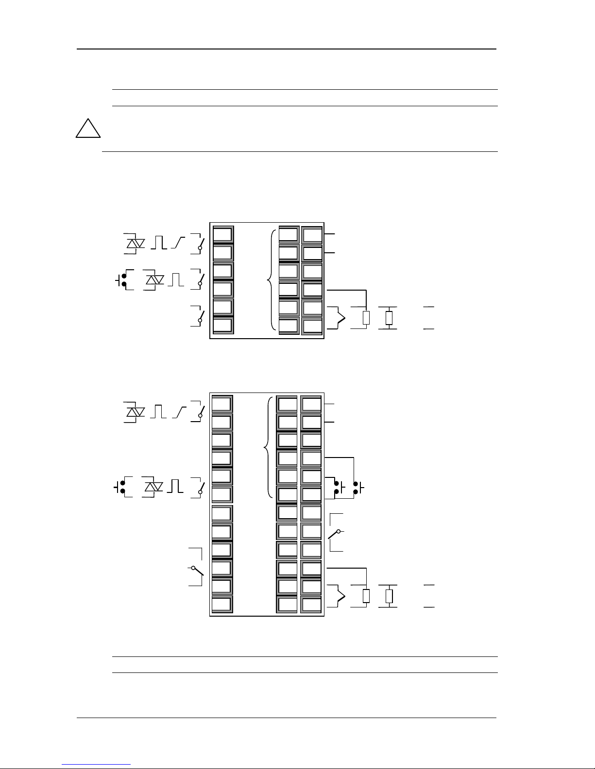
Model 2216e Connections
Figure 1-7: 2216e Terminals
Model 2208e Connections
Figure 1-8: 2208e Terminals
Do not use unused terminals as wire holders.
!
- -
-
HA
HB
HC
HD
HE
HF
+ +
+
L
N
VI
V+
V-
1A
1B
2A
2B
3A
3B
2.49Ω
- + T/C
Pt100 mA
-
+
mV/V
-
+
Output 1
Output 2
Output 3
Line
Neutral
Digital
Comms
Sensor Input
L
N
LA
LB
LC
AA
AB
AC
VI
V+
V-
3A
3B
3C
1A
1B
2A
2B
HA
HB
HC
HD
HE
HF
+ +
- -
+
-
+
+
-
2.49Ω
-
+
T/C
Pt100
mA
-
+
mV/V
-
+
Output 1
Output 2
Output 3
Line
Neutral
Digital
Comms
Sensor Input
Output AA
Logic Inputs
1-4 Part No. HA029989 Issue 3 July-14
2200e Series Installation and Configuration Handbook Installation
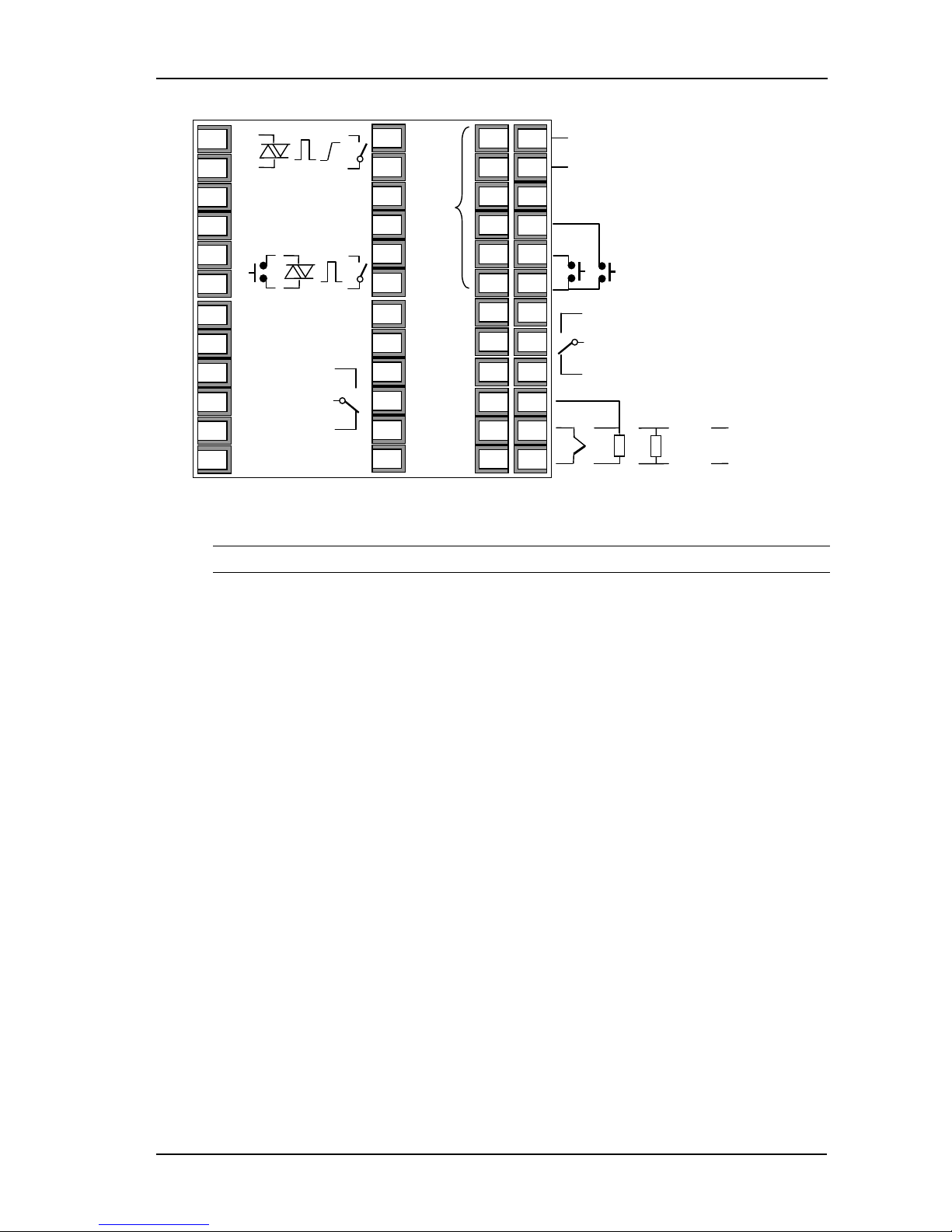
Model 2204e Connections
Figure 1-9: 2208e Terminals
Do not use unused terminals as wire holders.
1.4.1 Wire Sizes
All electrical connections are made to the screw terminals at the rear of the controller. They accept wire sizes from
0.5 to 1.5 mm
2
(16 to 22 AWG), and are protected by a hinged cover to prevent hands or metal making accidental
contact with live wires. Rear terminals should be tightened to a torque of 0.4Nm (3.5 lb in).
- -
L
N
LA
LB
LC
AA
AB
AC
VI
V+
V-
3A
3B
3C
1A
1B
2A
2B
HA
HB
HC
HD
HE
HF
+ +
+
-
+
+
-
2.49Ω
-
+
T/C
Pt100
mA
-
+
mV/V
-
+
Output 1
Output 2
Output 3
Line
Neutral
Digital
Comms
Sensor Input
Output AA
Logic Inputs
5C
5D
6A
6B
6C
6D
4A
4B
4C
4D
5A
5B
Part No. HA029989 Issue 3 July-14 1-5
Installation 2200e Series Installation and Configuration Handbook
1.4.2 Sensor input connections
The connections for the various types of input are as follows:
Figure 1-10: Sensor Input Connections
Do not connect more than one sensor to any one input.
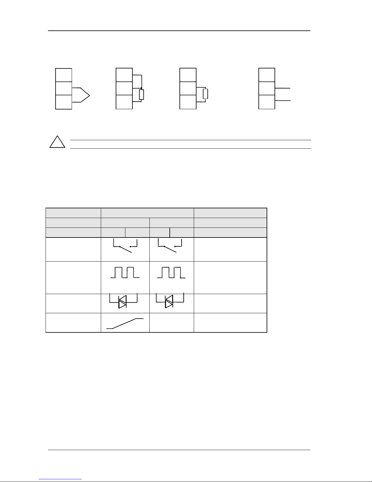
1.4.3 Outputs 1 and 2 connections
Outputs 1 and 2 can be any one of the types shown in the table below, configured to perform any one of the
functions shown.
To check which outputs are installed, and their configuration, refer to the ordering code and the wiring information
on the controller side labels.
Connections
Output 1 Output 2 Possible functions
Module type 1A 1B 2A 2B
Relay: 2-pin
(2A, 264 Vac max.)
Heating
Cooling
Alarms
Logic: non-isolated *
(18Vdc at 24mA)
+ - + -
♦
PDS modes 1 or 2 (SSRx)
Heating
Cooling
Alarms
Triac
(1A, 30 to 264Vac)
Heating or cooling
DC control: isolated
(18Vdc, 20mA max)
+
-
DC not available
in output 2
PID Heating or cooling
* Logic output can also be configured as logic input on module 2A.
♦
PDS Mode 1 & 2 are only supported in Module 1A.
Figure 1-11: Outputs 1 and 2 Connections
VI
V+
V-
VI
V+
V-
VI
V+
V-
VI
V+
V-
Thermocouple
Resistance
Thermometer
mA Input
Volts or mV
Inputs
+
PV
2.49Ω
current
sense
resistor
Line
Load
Line
Load
!
1-6 Part No. HA029989 Issue 3 July-14
2200e Series Installation and Configuration Handbook Installation
1.5 PDS Modes
PDS is a proprietary technique developed for bi-directional communication over a single pair of wires. There are
several operating modes.
In SSRx Load Doctor™ a logic output delivers a power demand signal to a TE10 solid state (SSR) relay and the SSR
responds with a single load circuit failure message.
In SSRx Enhanced Load Doctor™ a logic output delivers a power demand signal to an SSR and the SSR responds with
the ON state rms load current, and two fault messages - SSR failure or heater circuit failure.
1.6 Snubbers
The controller is supplied with ‘snubbers’ (15nF +100Ω) which should be wired across the relay or triac outputs when
switching inductive loads such as mechanical contactors and solenoid valves. The snubbers are used to prolong
contact life and to suppress interference when switching such loads. Snubbers pass 0.6mA at 110Vac and 1.2mA at
240Vac, which may be sufficient to hold in high impedance relay coils. They should not, therefore, be used in such
installations.
WARNING
When a relay contact is used in an alarm circuit ensure that the current passing through the
snubber when the relay contact is open does not hold in low power electrical loads and thereby
interfere with the failsafe operation of the alarm circuit.
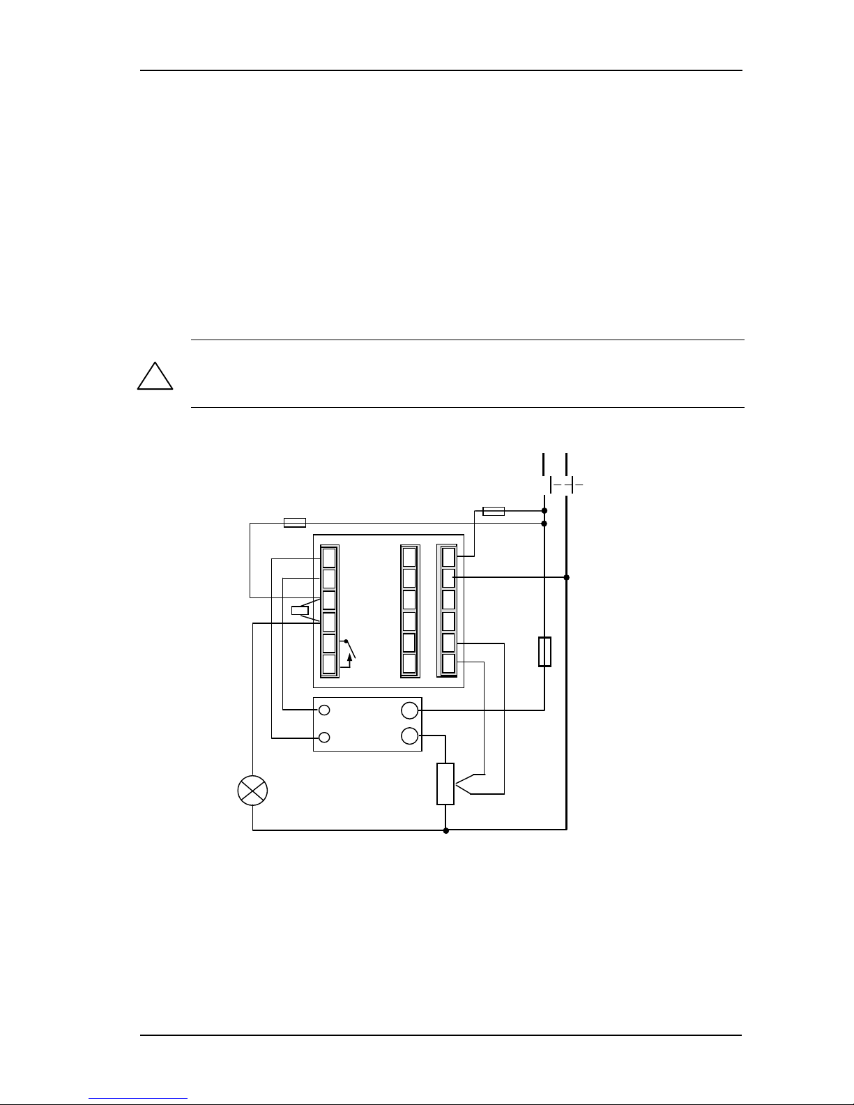
1.7 Typical single loop wiring diagram
Figure 1-12: Typical Wiring Diagram, Model 2216e Controller
Safety requirements for permanently connected equipment state:
• A switch or circuit breaker shall be included in the building installation
• It shall be in close proximity to the equipment and within easy reach of the operator
• It shall be marked as the disconnecting device for the equipment.
Note: a single switch or circuit breaker can drive more than one instrument.
!
Comms
Neutral
Heating
power fuse
(load
dependent)
Line
Thermocouple
Cooling Power
Fuse 1A(T)
Controller
Fuse 2A(T)
Solid State
Relay
e.g. TE10
+
-
Snubber
Heater
JA
JF
HA
HB
HC
HD
HE
HF
1A
1B
2A
2B
3A
3B
L
N
V1
V+
V-
Cooling
solenoid
valve
Circuit
breaker
Part No. HA029989 Issue 3 July-14 1-7
Installation 2200e Series Installation and Configuration Handbook
1.8 Logic Drive Fan Out
The logic outputs from the 2200 series controllers are capable of driving more than one solid state relay (SSR) in
series or parallel. The following table shows the number of SSRs which can be driven depending on type of SSR.
S = Series; P = Parallel.
Drive
mA
SVDA RVDA TE10S 425S
Logic DC Logic DC Logic DC Logic 10V Logic 24V Logic 20mA
Logic 18V@24 4S 6P 4S 4P 3S 3/2P 3S 3P 1S 2P 6S 1P
450 TC1027CE TE200S TC2000CE RS3DA
Standard TTL Multi-drive Logic V Logic DC Logic DC Logic DC
Logic 2S 3P 1S 2P 6S 1P 3S 4/3P 3S 4P 3S 2/1P 4S 2P
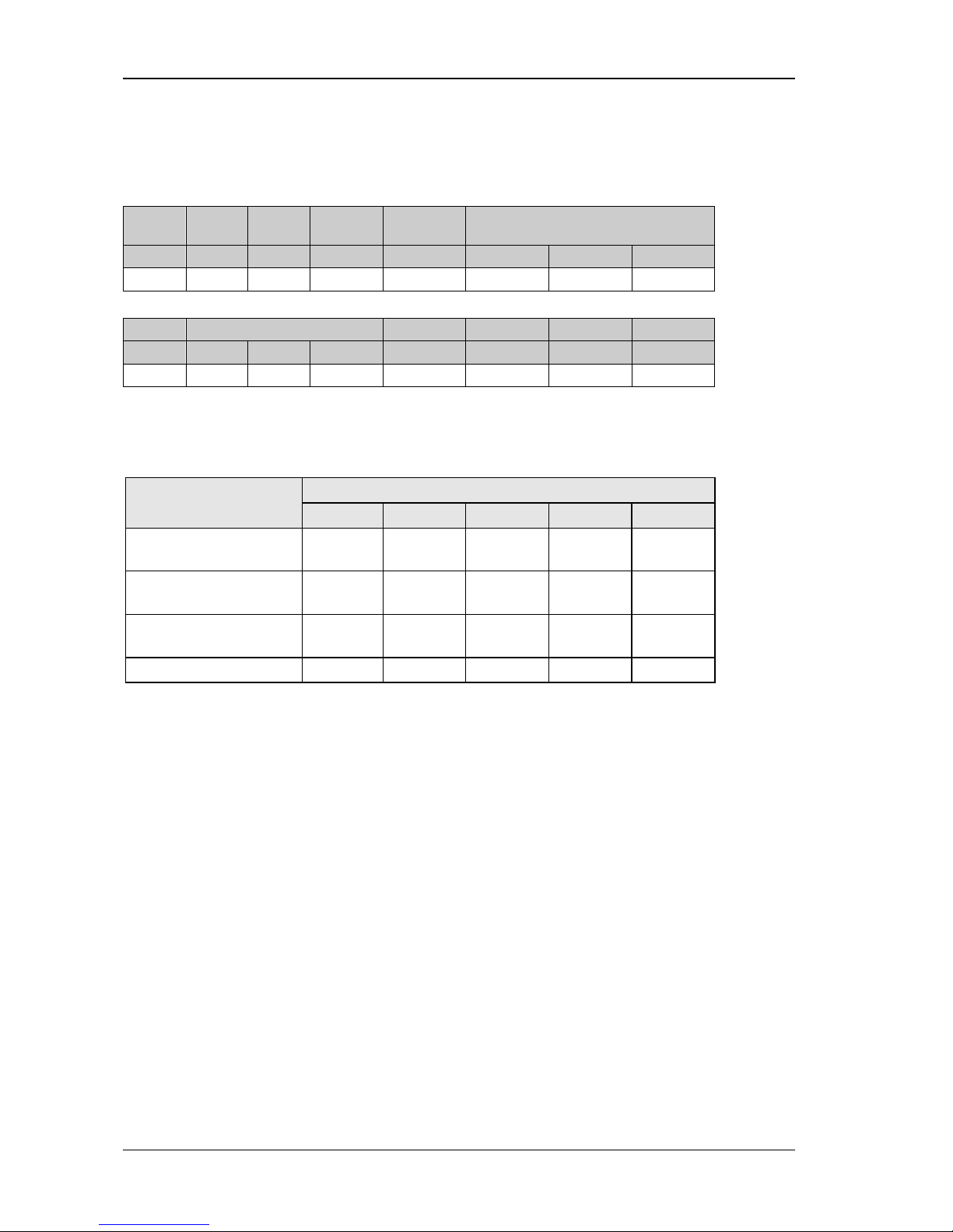
1.9 EIA232/485/422 Communication connections
The communication option can be either of four types shown in the table below:-
Connection
Communications type HB HC HD HE HF
4-wire EIA-422 serial
communications
A’
(RX +)
B’
(RX -)
Common A
(TX +)
B
(TX -)
2-wire EIA-485 serial
communications
Do not use Do not use Common A (+)
B (-)
EIA-232 serial
communications
Not used Not used Common A B
PDS Setpoint input Not used Not used Not used Signal Common
Figure 1-13: Communications Connections
1-8 Part No. HA029989 Issue 3 July-14
2200e Series Installation and Configuration Handbook Installation
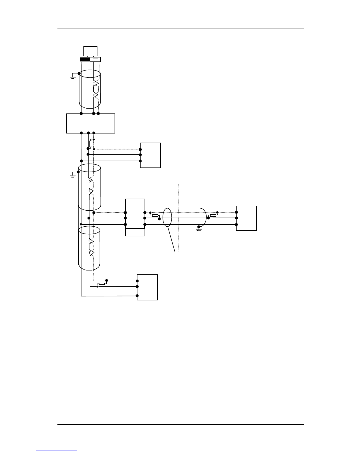
1.9.1 Wiring of EIA-485 serial communication links
Local
Local
Earth
HF +
Series 2000™
Controller
Com
Note:
All termination resistors are 220 ohm 1/4W carbon composition.
Local grounds are at equipotential. Where equipotential is not available wire into
separate zones using a galvanic isolator.
A
B
PC
Universal Convertor
RXTXCom
ComTXRX
Up to 32
controllers or
Interface Units may
be included on the
network
232
ComBA
Com
A
B
Galvanic
Isolation
Barrier
Com
A
B
Com
A
B
Local Earth
Com
A
B
Earth
Universal
Converter
MMI
Series 2000™
Controller
Series 2000™
Controller
For safety reasons,
do not connect to
local earth here.
HD
HF+
HE
HD
HF+
HE
HE
HD
Figure 1-14: 2-Wire EIA-485 Wiring
Standard EIA-485 is a 2-
wire connection which allows up to 32 controllers to
be multi-dropped from a single communications link over a distance of up
to 1.2Km. To ensure reliable operation of the communications link, (without
data corruption due to noise or line reflections) the connections between
the controller should be made using a twisted pair of wires inside a shielded
cable with the connections terminated with resistors in the manner shown in
this diagram. This diagram also shows the use of a Comms converter to
connect the 2-wire EIA-485 link into a standard EIA-232 computer port.
Common and Local
Earth cannot be
connected together.
Part No. HA029989 Issue 3 July-14 1-9
Installation 2200e Series Installation and Configuration Handbook
1.10 DeviceNet® Wiring to Series 2200e Controllers
This section covers the DeviceNet digital communications option for the model 2208e and 2204e controllers. To
configure DeviceNet communications refer to section 5.8.
1.10.1 DeviceNet Terminal Functions
Series 2200e
Terminal
CAN
Label
Color
Chip
Description
HA V+ Red DeviceNet network power positive terminal. Connect the red wire of the DeviceNet
cable here. If the DeviceNet network does not supply the power, connect to the
positive terminal of an external 11-25 Vdc power supply.
HB CAN_H White DeviceNet CAN_H data bus terminal. Connect the white wire of the DeviceNet cable
here.
HC SHIELD None Shield/Drain wire connection. Connect the DeviceNet cable shield here. To prevent
ground loops, the DeviceNet network should be grounded in only one location.
HD CAN_L Blue DeviceNet CAN_L data bus terminal. Connect the blue wire of the DeviceNet cable
here.
HE V- Black DeviceNet network power negative terminal. Connect the black wire of the DeviceNet
cable here. If the DeviceNet network does not supply the power, connect to the
negative terminal of an external 11-25 Vdc power supply.
Notes:
Power taps are recommended to connect the DC power supply to the DeviceNet trunk line. Power taps
include:
A Schottky Diode to connect the power supply V+ and allows for multiple power supplies to be connected.
Two fuses or circuit breakers to protect the bus from excessive current which could damage the cable and
connectors.
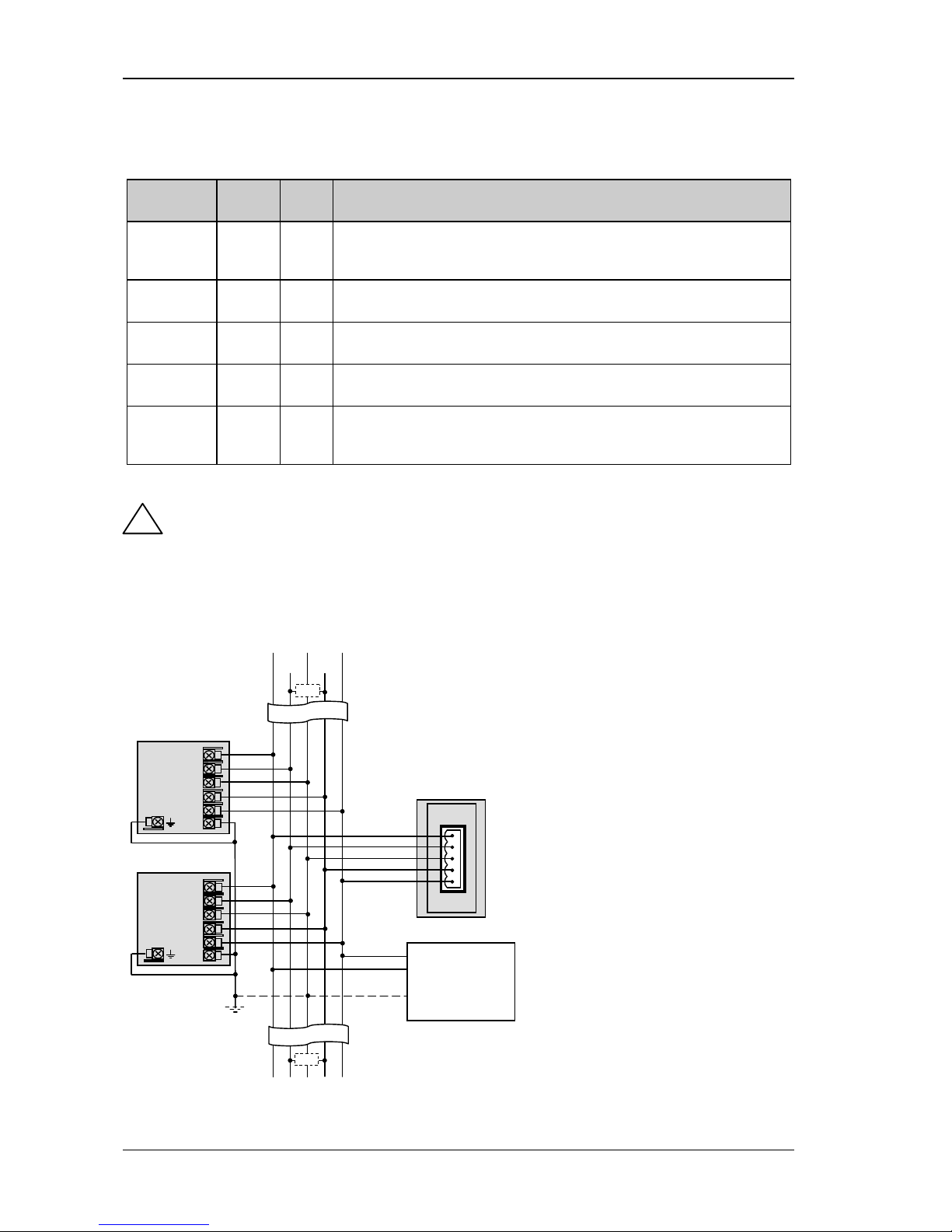
1.10.2 Wiring Interconnections for DeviceNet Communications
Figure 1-15: Wiring Connections for 2200e Series DeviceNet Controllers
!
Note:
The DeviceNet network is powered by an external
independent 24V supply which is separate from the
internal powering of the individual controllers.
The earth connection, HF, to be connected to the
main supply earth terminal at one point only.
* 121 1% 1/4W terminating resistor must be
connected across the blue and white wires at each
end of the DeviceNet trunk cable.
Note: this resistor is sometimes included in the
master or other devices but should only be switched
into circuit on the last device on the trunk cable.
DeviceNet Trunk Cable
DeviceNet Power
Supply
24Vdc (+/
- 1%)
250mV p
-p Ripple max
V+
V-
Ground
V- Shield V+
↑
Further Devices
2200_1
HA
HB
HC
HD
HE
HF
Drop
Line
MASTER
Drop Line
Drop
Line
Further Devices
↓
2200_2
HA
HB
HC
HD
HE
HF
*
*
CAN-L CAN-H
1-10 Part No. HA029989 Issue 3 July-14
2200e Series Installation and Configuration Handbook Operation
2 Operation
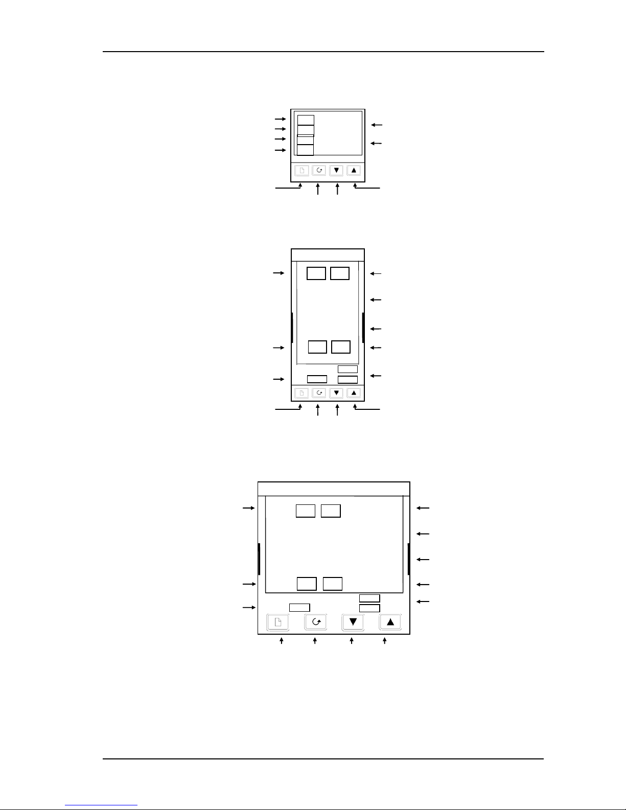
2.1 Front Panel Layout
Figure 2-1: Model 2216e Front Panel Layout
Figure 2-2: Model 2208e Front Panel Layout
Figure 2-3: Model 2204e Front Panel Layout
Tip: The display may flash an alarm message. Refer to the Parameter Tables in section 2.9 for a complete
list and meaning of the messages.
Down
Button
Manual mode
Page
Button
Scroll
Button
Up
Button
Remote Setpoint
Output 2
Upper readout
Lower readout
Output 1
Setpoint 2 active
Setpoint rate limit active
20.00
20.00
OP1
OP2
2204e
SP2 REM
MAN
RUN
HOLD
Page Button
Scroll Button
Down Button
Up Button
Manual mode
Setpoint 2 active
PDS Remote Setpoint
Setpoint rate limit active
20.0.0
20.0.0
OP1
OP2
SP2
REM
2208e
Output 1
Output 2
Upper readout
Lower readout
MAN
RUN
HOLD
PDS Remote Setpoint
Setpoint 2 active
Output 1
Actual Temperature (Process Value)
Output 2
Required Temperature (Setpoint)
20.0
23.0
OP1
OP2
SP2
Rem
Page Button
Scroll Button
Down Button
Up Button
Part No. HA029989 Issue 3 July-14 2-1
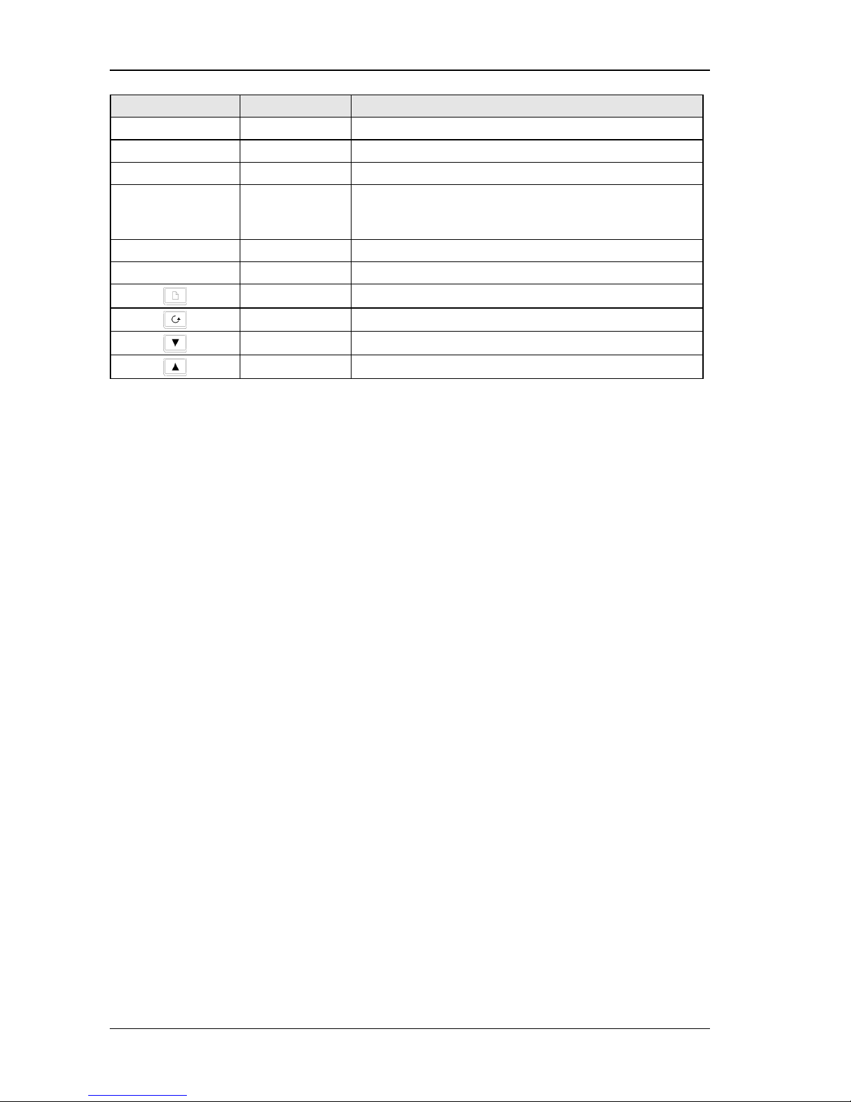
Operation 2200e Series Installation and Configuration Handbook
Button or indicator Name Explanation
OP1 Output 1 When lit, it indicates that heating output is on.
OP2 Output 2 When lit, it indicates that cooling output is on.
SP2 Setpoint 2 When lit, this indicates that Setpoint 2 has been selected.
REM Remote Setpoint When lit, this indicates that the PDS remote Setpoint input has
been selected. ‘REM’ is also used to indicate that user comms is
active.
MAN Manual light When lit, it indicates that manual mode has been selected
RUN Run light When lit, it indicates that Setpoint rate limit is active.
Page button Press to select a new list of parameters.
Scroll button Press to select a new parameter in a list.
Down button Press to decrease a value in the lower readout.
Up button Press to increase a value in lower readout.
Figure 2-4: Controller Buttons and Indicators
Tip: For Valve Positioning, please refer to section 8 ‘Motorised Valve Control.
2-2 Part No. HA029989 Issue 3 July-14
2200e Series Installation and Configuration Handbook Operation
2.2 Getting Started
Thank you for selecting this controller.
This section shows the principle of operation. Views are generally shown for 2404 controller.
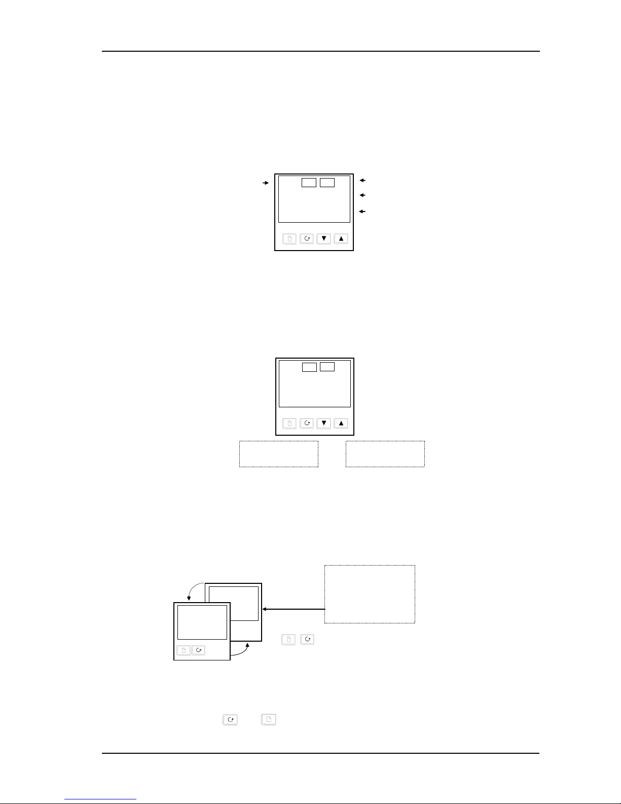
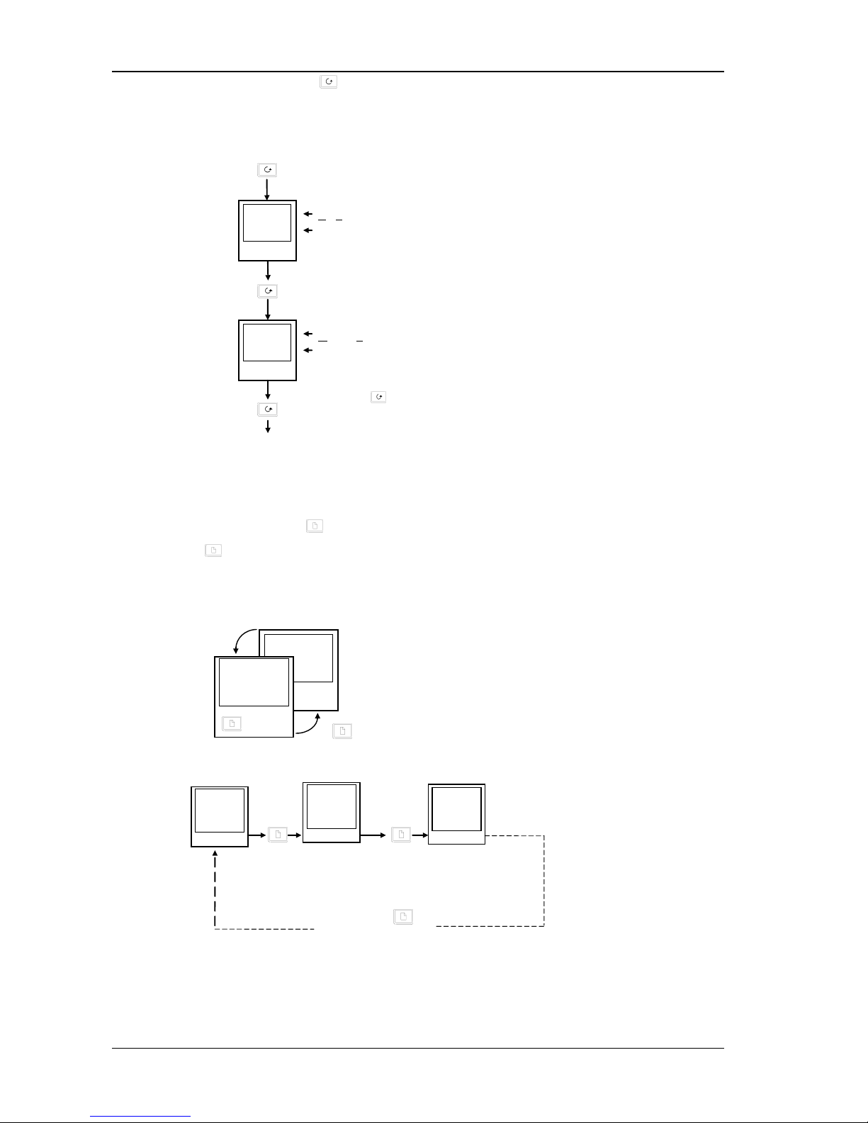
2.2.1 To View The Process Value and Setpoint
Install and wire up the controller as explained in section 1.4 and switch on.
Following a 3 second self-test sequence, this is the display you will see,
Figure 2-5: The "HOME Display"
Tip: The display may flash an alarm message. Refer to the Parameter Tables in section 2.9 for a
complete list and meaning of the messages.
2.2.2 To Adjust The Setpoint
Figure 2-6: The Lower Readout Shows the Setpoint
After 2 seconds the lower readout will ‘blink’ indicating that the new value has been accepted.
For everyday use you may not need to do anymore than this.
2.2.3 To View The Display Units
Figure 2-7: Viewing the Display Units
Tip: If you get lost, pressing and together will return you to the Home display.
Press and hold to
increase temperature
Press and hold to
decrease temperature
20.0
140.0
OP1
OP2
Output 1
Actual Temperature (Process Value)
Output 2
Required Temperature (Setpoint)
20.0
23.0
OP1
OP2
Display Units
“
C
Degrees Centigrade
“
F
Degrees Farenheit
K
Degrees Kelvin
No units - Linear inputs
Momentarily press either button
0.5 sec.
23.0
“
C
20.0
140.0
Part No. HA029989 Issue 3 July-14 2-3
Operation 2200e Series Installation and Configuration Handbook
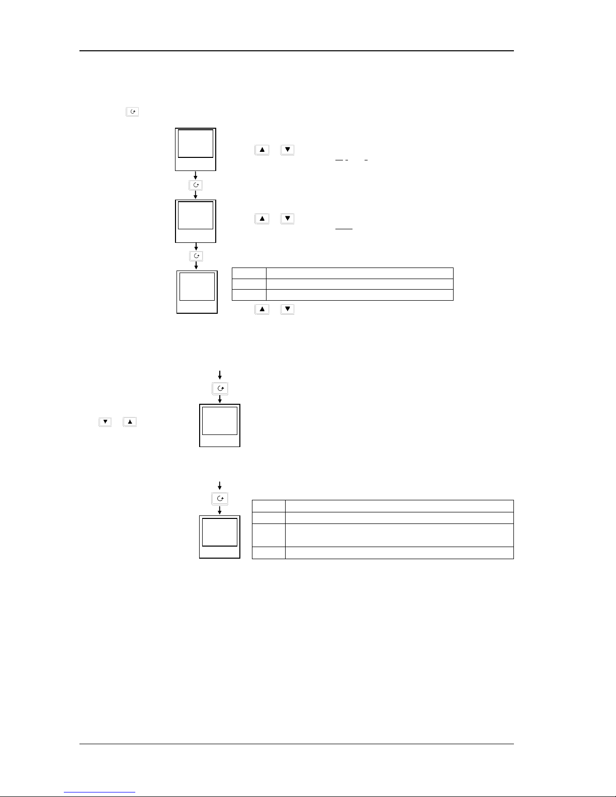
2.2.4 Use Of The ‘SCROLL’ Button
Pressing the scroll button will display the output power level. Continued pressing will display further parameters in
the operator scroll list.
Figure 2-8: The Scroll Button
2.2.5 Use Of The ‘PAGE’ Button
The page button accesses parameter LISTS.
Parameters are settings in the instrument which, generally, can be changed by the user to suit the process. Examples
are: Alarms, Self Tune, etc. They are found under headings called LISTS and a full set is given later in this chapter.
Figure 2-9: The Page Button
Tip: The actual list headings may be longer or shorter than indicated above and you can customise this for the
operator’s convenience in EDIT level, section 3.
Keep pressing to return to the Home display or select
further parameters (if available)
2nd press
3rd press
Output
Actual output level %
OP
100.0
Manual/Auto
Actual state
m-A
Auto
Keep pressing to
select more list headings
1st press
0.2 sec.
23.0
“
C
20.0
1400
3rd press
2nd press
AL
LiSt
atun
LiSt
20.0
14.00
2-4 Part No. HA029989 Issue 3 July-14
2200e Series Installation and Configuration Handbook Operation
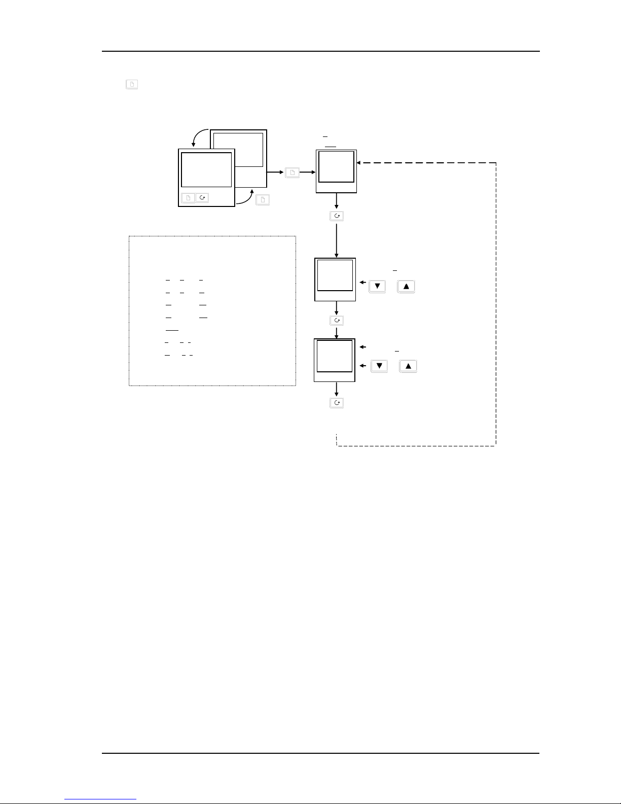
2.3 Parameter Lists
Press to choose a LIST - “ALARMS” is a good one. This list allows you to set the alarm trip levels. The
parameters which appear in the list will vary according to the configuration of your controller.
Tip: If, at any time, no key is pressed within 45 seconds, the display will always return to the “HOME” display.
A description of the parameter lists is given in section 2.9.
Figure 2-10: Choosing a List of Parameters
or to change trip level
or to change trip level
1st press
2nd press
0.2 sec.
23.0
“
C
20.0
140.0
There are 4 alarms in the controller. The first
character is the alarm number. The following
three letters indicate alarm type as follows:
-FSL
Full Scale Low
-FSH
Full Scale High
-dHi
Deviation High
-dLo
Deviation Low
-dEv
Deviation Band
-Lcr
Low current
-Hcr
High current
Disabled alarms will not be displayed.
Section
7 gives a full description of alarms.
Alarm
List
Alarm 1
Now press the
SCROLL button
2nd press
AL
LiSt
1---
50.0
2---
200.0
Keep pressing
2. to scroll through further parameters
3. to return to list header
Alarm 2
Part No. HA029989 Issue 3 July-14 2-5
Operation 2200e Series Installation and Configuration Handbook
2.4 Manual or Automatic Control
The controller can be used in two modes:
Automatic mode - in which the output power is automatically adjusted to hold the temperature at the required
value. The controller normally operates in this mode.
Manual mode - in which the output is manually adjusted by the Operator. In this mode the ‘MAN’ light will be on.
One other mode is available:
Remote setpoint - The setpoint is generated as an input signal from a master 2000 or 3000 series controller. In this
mode the REM light is on.
2.4.1 To Select Auto/Manual Operation
Figure 2-11: Auto/Manual Select
2.4.2 To Adjust Output Power in Manual Mode
Figure 2-12: The "Home" Display in Manual Mode
Tip: Manual mode is generally used for test and commissioning purposes, take care not to leave the controller in
this mode since damage to the process or personal injury could occur.
or to select
Auto automatic mode
Man manual mode
2 sec.
23.0
“
C
20.0
1st press
Output
Actual output level %
Manual/Auto
2nd press
3rd press
OP
100.0
m-A
Keep pressing
to return to “HOME” display
Actual Temperature (Process Value)
20.0
50.0
OP1
OP2
Output Power Demand
Manual Indicator on
Press and hold to increase power
Press and hold to decrease power
2-6 Part No. HA029989 Issue 3 July-14
2200e Series Installation and Configuration Handbook Operation
2.5 SETPOINT 1 OR SETPOINT 2
The instrument has the facility to select between two setpoints. This may be useful, for example, where it is required
to switch control between two different setpoints or to control in a standby condition, thus avoiding the necessity to
change the setpoint manually each time.
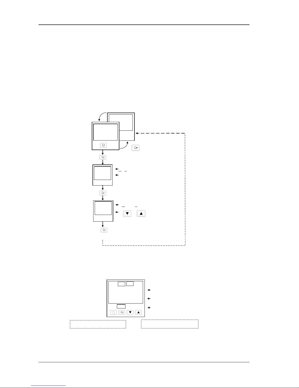
2.5.1 To Select Setpoint 1 or Setpoint 2
This may be done in two ways:-
1. By an external switch or relay contact wired to a digital input
2. Through the front panel using the SP list
Figure 2-13: Selecting Setpoint 1 or 2
2.6 Ramp Dwell Function
The ramp dwell function is selected by turning the setpoint rate limit parameter SPrr to a value. It can be set to
RUN in two ways:-
1. Through the front panel using the SP list
2. By an external switch or relay contact wired to a digital input configured for reset (rset). When closed the
program will reset. When open the program will run. To run the program from the initial reset state, it is
necessary to first close the switch then open it.
The controller will then ramp from setpoint 1 to setpoint 2 at a rate set by the SPrr parameter.
When the controller reaches setpoint 2 it can remain at this level for a timed period, using the dwel parameter.
At the end of the dwell period the action of the controller is determined by the End Type parameter End.t.
Press to select SP list
20.0
140.0
Setpoint List
Press scroll button to SSEL
SP
LiSt
SSEL
SP
Press
o r
to change between SP 1 and SP 2
When setpoint 2 is selected
the SP2 beacon illuminates.
Part No. HA029989 Issue 3 July-14 2-7
Operation 2200e Series Installation and Configuration Handbook
2.6.1 To Set up a Ramp/Time Program
Set setpoint 1 to the value at which to start the ramp. Set setpoint 2 to the value which you wish to ramp to. This is
described in the previous section.
Figure 2-14: Ramp/Dwell Program
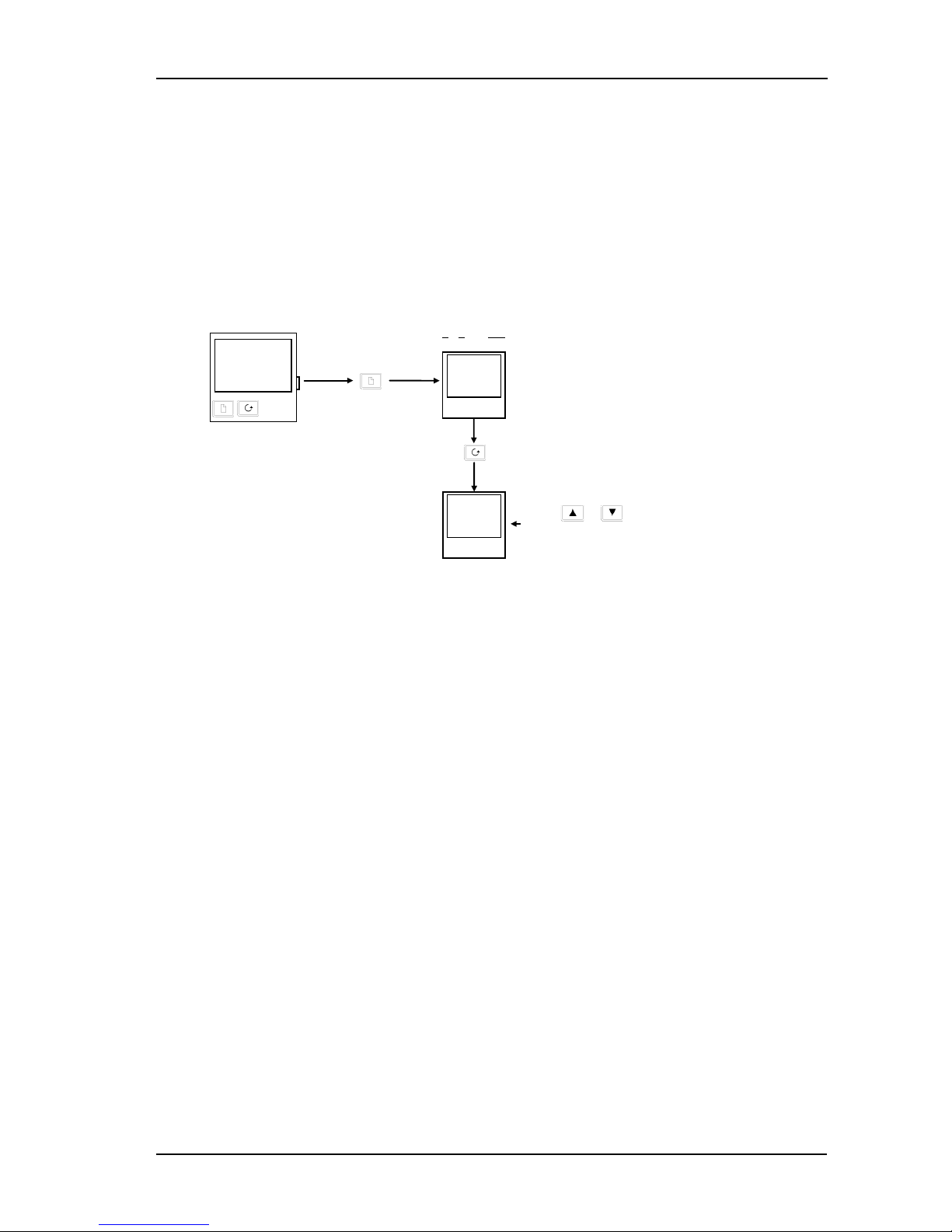
2.6.2 To Run the Program
Figure 2-15: Program Run
A program may also be reset or run using an external switch contact if a digital input has been configured. See
Configuration section 5.
2.6.3 Power Failure During Program Run
1. During Ramp. After return of power, the working setpoint will servo to the current PV value, and the ramp
continues to SP2 followed by the timed dwell.
2. During Dwell. After return of power the working setpoint will servo to PV, the ramp continues to SP2 followed
by full programmed dwell. In effect this causes the program to restart.
Tip: Use the Hide, Reveal and Promote features to customise the display for a programmer. See section 3.
In Run mode the controller will ramp from SP 1 to SP 2 at 20.0 units per minute
Press scroll button to dwEl
SPrr
20.0
dwel
60.0
Press
or
to set the SP ramp rate in units per minute
Press
o r
to set the dwell time in minutes
In Run mode the controller will dwell at SP 2 for 60 minutes
Press scroll button to End.t
End.t
rSEt
In Run mode the controller will reset at the end of the dwell time. Other choices are:-
HoLd
The program will freeze
StbY
The program will go into standby
dwel
The program will dwell for an unlimited period
Press
o r
to choose the action required at the end of the dwell time
Now press until
SPrr
is displayed
From the previous view, press
scroll button to ProG
Prog
run
Press or to choose run
To reset the controller to start conditions, select
rSEt
From the previous view,
press scroll button to StAt
StAt
rmp
The status may be any one of the following:
rmp
Ramping from SP1 to SP2
dwel
Dwelling at SP2
End
The program is complete.
If
End.t
=
rSEt, End
will flash briefly before changing to
OFF
OFF
The program is in the reset state
In Full access level the Status of the
program can be read as follows:
-
2-8 Part No. HA029989 Issue 3 July-14
2200e Series Installation and Configuration Handbook Operation
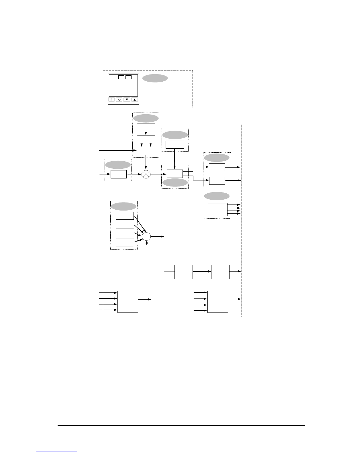
2.7 Location of Parameters - Block Diagram
The controller consists of a number of internal function blocks connected together to create a temperature
controller. Each function block has a number of parameters found in lists to which the user has access. The block
diagram shows location of these parameters within the controller.
Figure 1-14 Controller Block Diagram
20.0
23.0
OP1
OP2
For example
Output power
Setpoint
Auto/Manual
HOME List
LA*, LB*,
Module 2
Logic I/P
Alarm 1
Input
SP
PLANT INPUTS
PLANT OUTPUTS
Remote SP
TCs
PRT
Pyrometer
mA. mV, Volts
Relay, Logic, triac,
mA, Volts
Setpoint
PV
SP List
PiD List
OP List
iP List
Atun List
Control
Parameters
Digital
Comms
RS232
RS484
RS422
cms List
Digital Comms
Retrans-
mission
mA,
Volts
OP
PV
Err
SP
2 to 5 logic inputs
Functions
listed in
LA/LB
Relay
output
Relay, Logic,
triac
Alarm 2
Alarm 3
Alarm 4
Other
alarms
Normal/
Invert
OR
AL List
These are available in configuration level only
Alarms
Logic Inputs
Retrans-mission
Display Parameters
* LA & LB are not
available in 2216
Part No. HA029989 Issue 3 July-14 2-9
Operation 2200e Series Installation and Configuration Handbook
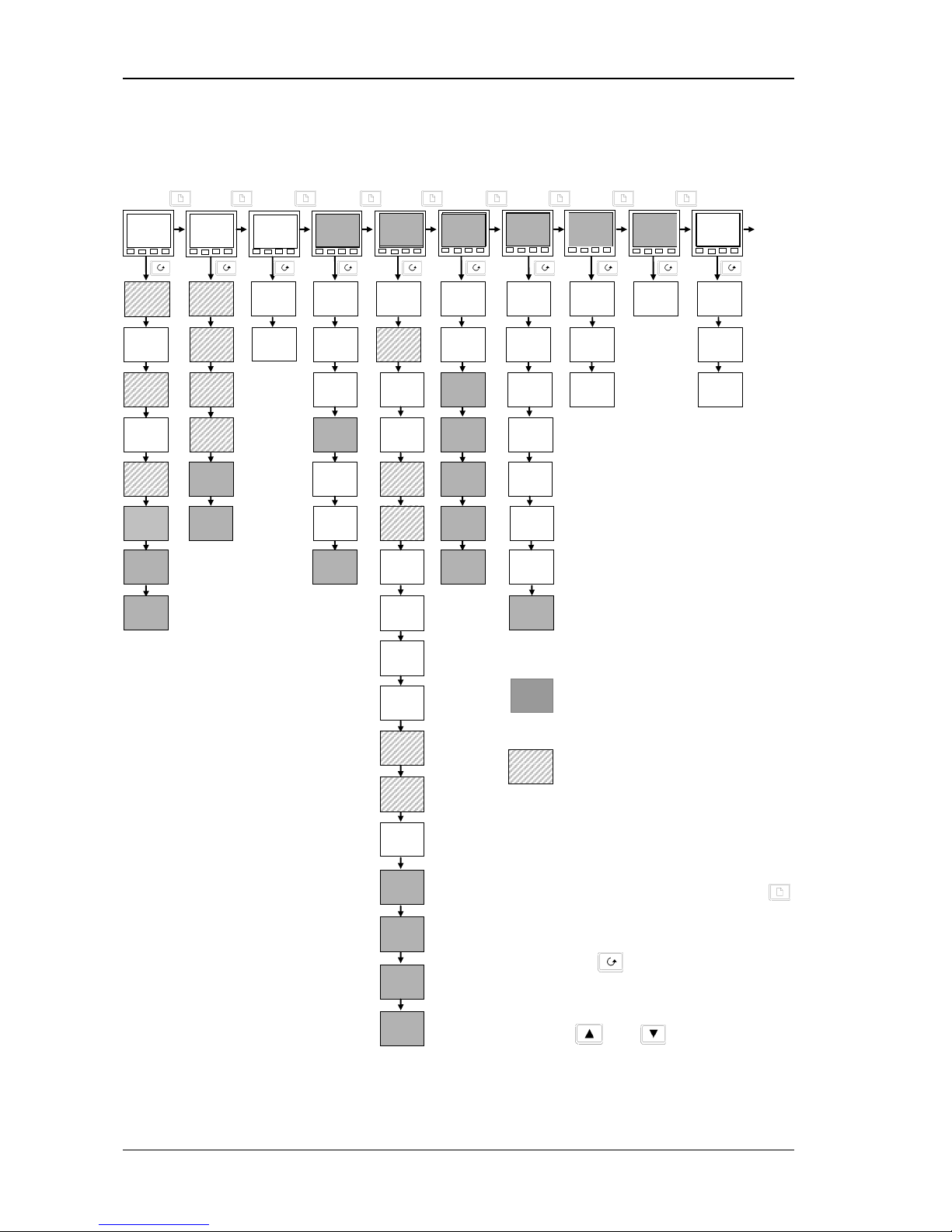
2.8 Navigation Diagram
The navigation diagram shows a complete list of possible parameters. However, some may not appear because they
are dependent upon a particular controller variant.
Figure 2-16: Navigation Diagram
20.0
20.0
Home
List
Atun
LiSt
Pid
LiSt
PID
(1)
List
AL
LiSt
Alarm
List
Autotune
List
SP
LiSt
Setpoint
List
OP
100.0
AmPS
5
5
m-A
Auto
1---
2
100.0
2--
2
20.00
3--
2
0.0
4--
2
0.0
TunE
OFF
Lbt
OFF
Pb
50
Ti
300
td
50.0
rES
0.0
Lcb
Auto
Hcb
Auto
SSEL
SP 1
L-r
8
Loc
SP 1
20.0
SP 2
0.0
rm.SP
8
0.0
Loc.t
8
0.0
rEL.C
1.00
SP1.L
3
0.0
SP1.H
3
10
0.0
Loc.L
8
100.0
Loc.H
8
0.0
SPrr
OFF
SP2.H
3
100.0
SP2.L
3
0.0
VPOS
4
100.0
WSP
9
20.0
SP
20.0
diSP
stnd
CID
1.0
HY
1.0
Adc
Notes:
1. Either the PID list or the On/Off list
will be present depending upon the
type of control in use.
2. The last three characters depend
upon the type of alarm configured
3. Absolute setpoint limits are set in
configuration, see section 5.
4. VPOS only for VP. Refer to VP Ch8.
5. Amps is Mode 2 or Mode 5 PDSIO.
6. mtr used for VP version. Refer to
VP Ch 8
7. Beware! Used for calibration. See
section 6.
8. Is only available if using PDSIO®
comms in the HA slot.
9. WSP is available if using ramp to
setpoint.
Return
to
Home
Display
DwEl
0.0
End.t
rset
ProG
rset
StAt
OFF
iP
LiSt
Input
List
oP
LiSt
Output
List
CmS
LiSt
Comms
List
ACCS
LiSt
Access
List
OnOF
LiSt
On Off
List
(1)
FiLt
1.0
CAL
7
FACT
CAL.S
7
Lo
OP.Lo
0.0
OP.Hi
100.0
Sb.OP
100.0
CYC.H
20.0
ont.H
1.0
CYC.C
5.0
hYS.H
1.0
hYS.C
1.0
HC.db
0.0
Addr
1
coDE
PASS
Goto
OPEr
ont.C
1.0
ConF
0
OFST
0.0
Mtr
6
20.0
AdJ
7
0.0
CJC
21.0
mV
1.17
Complete lists or individual parameters
normally hidden in Operator level. To see
all the available parameters you must select
Full level. See section 3 Access Levels
Only displayed when option selected
Summary
To step through list headers press the Page button
until the required header is obtained
To step through parameters within a particular list press
the Scroll button
until the required parameter is
obtained
To change the value (or state) of a parameter press the
Raise button
or the Lower button
2-10 Part No. HA029989 Issue 3 July-14
2200e Series Installation and Configuration Handbook Operation
The remainder of this chapter provides a complete list of all parameters available.
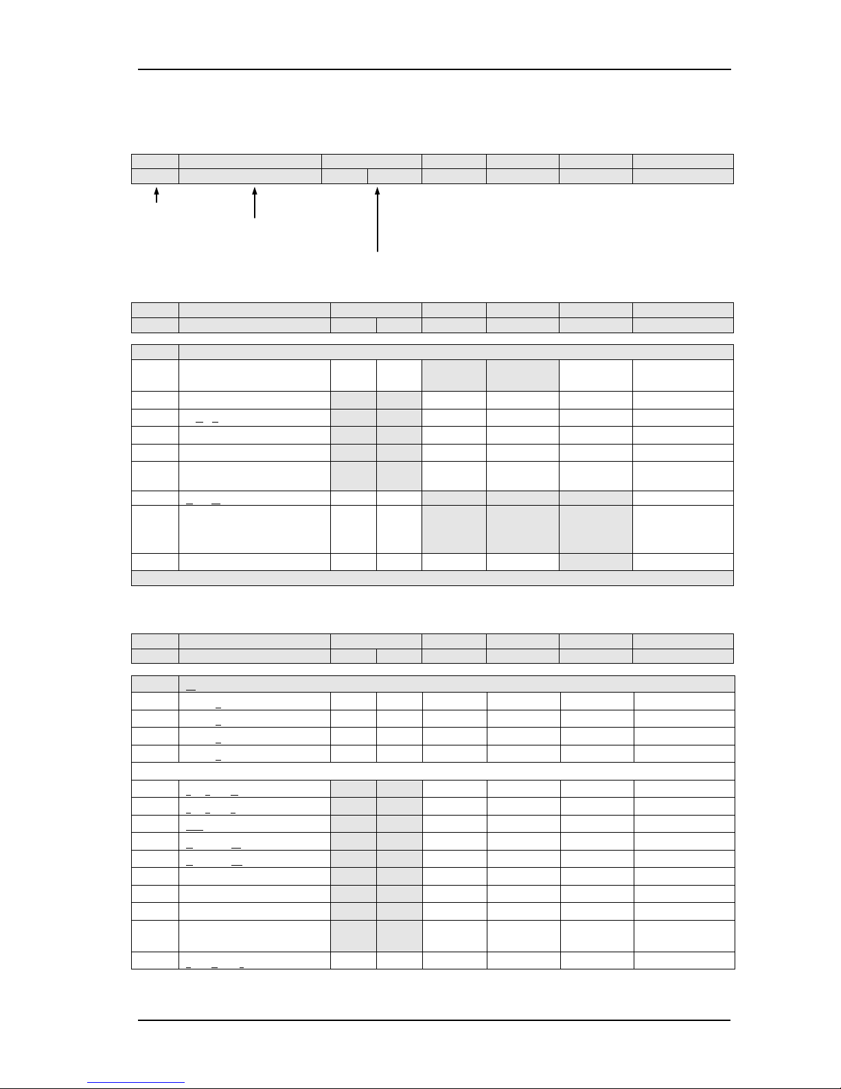
2.9 Parameter Tables
The tables which follow list all parameters that are available in Full operator level.
Name
Parameter Description
Default Value
Min Value
Max Value
Units
Customer Setting
UK
USA
Display mnemonic
Brief description of
parameter or function
Factory configured value
2.9.1 HOME Display
Name
Parameter Description
Default Value
Min Value
Max Value
Units
Customer Setting
UK
USA
Home List
Home
Measured Value and
Setpoint(SP)
SP=25°C SP=75°F
as display
vPoS
Valve positioner output power
0.0 100.0
%of mtr
OP
% Output Level
-100.0 100.0
%
wSP
Working setpoint
as display
SP
Setpoint
-999 9999
as display
AmPS
Heater current (PDS modes 2
and 5)
0 100 Amps
m-A
Auto/manual select
Auto Auto
diSP
Configure lower readout of
home display
StD StD
None“ StD“
AmPS“ OP“
stat“ vPoS
Cid
Customer ID
0 0 0 9999
Additional parameters may appear in the Home display if the ‘promote’ feature has been used (see Edit Level, section 3).
2.9.2 Alarm List
Name
Parameter Description
Default Value
Min Value
Max Value
Units
Customer Setting
UK
USA
AL
Al
arm List
1---
Alarm 1 set point value
0 0
as display
2---
Alarm 2 set point value
0 0
as display
3---
Alarm 3 set point value
0 0
as display
4---
Alarm 4 set point value
0 0
as display
In place of dashes, the last three characters indicate the alarm type, as follows:
-FSH
Full Scale High alarm
-999 9999
as display
-FSL
Full Scale Low alarm
-999 9999
as display
-DEv
Deviation band alarm
0 9999
as display
-dHi
Deviation High alarm
0 9999
as display
-dLo
Deviation Low alarm
0 9999
as display
-Lcr
Low current alarm
0 100
AMPS
-Hcr
High current alarm
0 100
AMPS
Hy
Hysteresis
0 9999
as display
Hy.EV
Hysteresis for event alarms.
See Note 1
0 9999
as display
Lbt
Loop break time
OFF OFF 0 9999
secs
Note 1: This parameter has been added from software version 4. Event alarms are configured in the AL Conf List.
Part No. HA029989 Issue 3 July-14 2-11
 Loading...