

Eurowater SE 30 Quick Manual
SILHORKO-EUROWATER A/S Phone + 45 86 57 12 22
DK-8660 Skanderborg info@eurowater.com
Denmark www.eurowater.com
Our World is Water
Instructions L30C-30A-UK-02-01
QUICK GUIDE
SE30 CONTROL PANEL
SOFTWARE VERSION 30ROS02___
1. DATA
Nominal operating voltage............................................................. 24 VDC
Allowed supply voltage.......................................................20.4-28.8 VDC
Maximum current consumption ..................................................... 80 mA at 24 VDC
Digital input.................................................................................... 12
Digital output, direct......................................................................... 9
Maximum current, reserve.......................................................... 1 A
Voltage ..........................................................................20.4-28.8 VDC
Digital output, potential-free ............................................................ 5
Maximum current........................................................................ 1 A
Maximum voltage .....................................................................30 VDC
Total maximum current, outputs...................................................... 5 A
Analog input.....................................................................................2 4-20 mA
Analog output .................................................................................. 1 4-20 mA
Protection class ..........................................................................IP54
Ambient temperature..................................................................0-50 °C
Storage temperature .........................................................-20 to +60 °C
Relative humidity ......................................................................10-80 %, non-condensing
L30C-30A-UK-02-01 1 May 2009
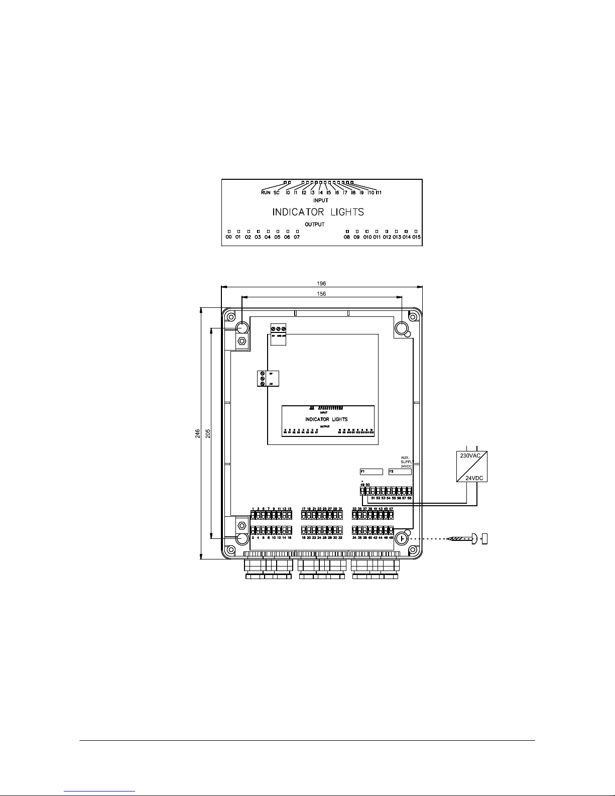
2. ELECTRICAL CONNECTION AND INSTALLATION
RUN: CPU is active
SC: CPU error
I0-I11: Digital input
O0-O15: Digital output
F1 fuse for CPU (T1A 5 x 20 mm)
F2 fuse for outputs (T5A 5 x 20 mm)
L30C-30A-UK-02-01 2 May 2009
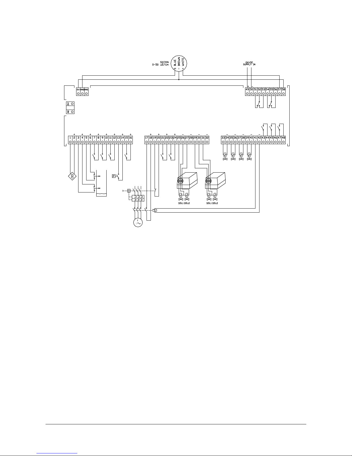
3. CONNECTION OF TANKS
0V+AN0: Conductivity input, analog A0+0V: Conductivity output, analog
0V+AN1: Available input, analog
1+2: I0 Water meter 25+26: O0 Sol 1 T1
3+4: I1 LS min. 27+28: O1 Sol 2 T1
5+6: I2 LS max. 29+30: O2 Sol 1 T2
7+8: I3 External operation request 31+32: O3 Sol 2 T2
9+10: I4 External regeneration start 33+34: O4 Outlet valve T1
11+12: I5 Block automatic regeneration 35+36: O5 Outlet valve T2
13+14: I6 Pressure switch 37+38: O6 RO inlet valve
15+16: I7 Block operation 39+40: O7 RO quality rinse valve
17+18: I8 RO pump in operation 41+42: O8 RO pump
19+20: I9
RO protective motor switch, disconnected
43+44: O9 Alarm (potential-free)
21+22: I10 Conductivity = OK 45+46: O10 Dosing (potential-free)
23+24: I11 Alarm reset 47+48: O11
Output configuration (potential-free)
49+50 Supply 24 VDC
51+52+53
Regeneration, softening (potential-free)
54+55+56 Alarm (potential-free)
57+58 24 VDC miscellaneous
L30C-30A-UK-02-01 3 May 2009
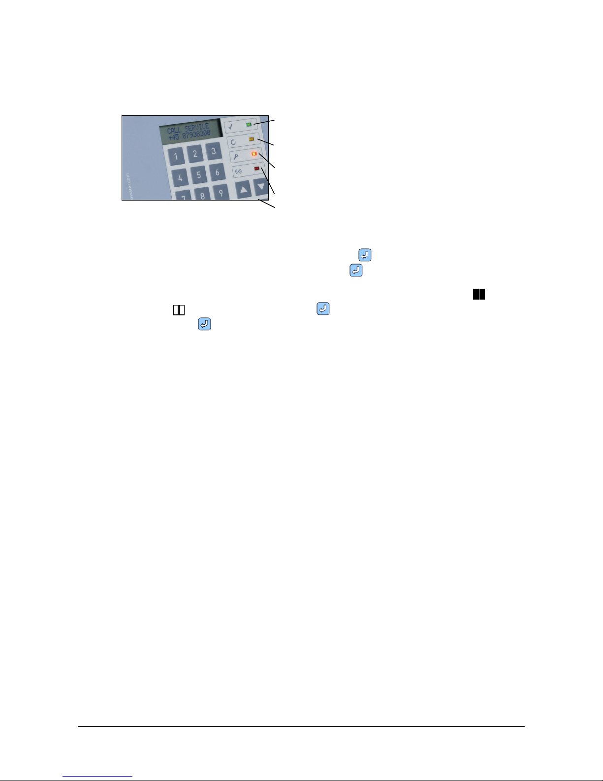
4. CONFIGURATION MENU
- setting and changing program parameters and plant functioning.
Power on
Regeneration, softening
Call service
Alarm
4 arrow keys
Use the arrow keys to change between display level and setting level and to navigate between
the various displays.
To enter or change a numerical value, first press ENTER until the cursor blinks. Now enter
the desired value on the numeric keypad. Press ENTER to confirm your entries.
Special functions can be enabled or disabled. These functions are displayed with when
enabled and when disabled. Press ENTER to select a function and the symbols blink.
Now press ENTER again to confirm your selection.
If you want to disable a function, the procedure is the same.
If the control is in configuration menu, and the keypad has not been touched for approximately
three minutes, the control will automatically change to operation menu.
Enter code 111 or 222 to access configuration menu from operation and display menu.
 Loading...