

Euro Video EVD-08/050A1MJN, EVD-04/050A1MJN, EVD-16/100A4JN User Manual

User Manual
EVD-08/050A1MJN www.eurovideo-cctv.com
Thank you for purchasing our product.
Please read this User’s Manual before
using the product. Change without Notice
8 Channel Digital Video Recorder
User’s Manual

User Manual
EVD-08/050A1MJN www.eurovideo-cctv.com
2
CAUTION
RISK OF ELECTRI CAL
SHOC K. DO NO T OPEN !
CAUT IO N: TO REDU CE TH E RISK OF ELEC TRI CAL SH OCK ,
DO NOT RE MOV E COVE R (OR BA CK), NO USER
SERV ICE ABLE PARTS REF ER SER VIC ING TO
QUAL IFI ED SE RVIC E PERS ONNE L.
Safety Precautions
The lightning flash with arrowhead symbol, within an equilateral
triangle, is intended to alert the user to the presence of insulated
dangerous Voltage within the product’s enclosure that may be
sufficient magnitude to constitute risk of electrical shock to persons.
The exclamation point within an equilateral triangle is intended to alert
the user to the presence of important operation and maintenance
(servicing) instructions in the literature accompanying the appliance.
WARNING: TO PREVENT FIRE OR SHOCK HAZARD, DO NOT
EXPOSE UNITS NOT SPECIFICALLY DESIGNED FOR
Attention: installation should be performed by qualified service
Personnel only in accordance with the National Electrical Code or
applicable local codes.
Power Disconnect. Units with or without ON-OFF switches have
power supplied to the unit whenever the power cord is inserted into
the power source; however, the unit is operational only when the
ON-OFF switch is the ON position. The power cord is the main power
disconnect for all unites.
There are no serviceable parts for this unit, call for your agent for
details.
Warranty
and Service

User Manual
EVD-08/050A1MJN www.eurovideo-cctv.com
3
Before installing stand alone DVR, be sure to thoroughly review and follow the instructions in
this Users Manual. Pay particular attention to the parts that are marked NOTICE.
Also, when connecting with external application, first turn the power OFF and follow manual
instruction for appropriate installation.
1. This document is intended for both the administrator and users of stand alone DVR
Model.
2. This manual contains information for configuring, managing and using stand alone
DVR Model.
3. To prevent fire or electrical shock, do not expose the product to heat or moisture
4. Be sure to read this manual before using stand alone DVR Model.
5. For questions and technical assistance of this product, contact your local dealer.
►Strong recommendation on installation of the DVR unit
1. Check electricity at the place you want to install the DVR unit is stable and meets our
electricity requirements. Unstable electricity will cause malfunction of the unit or give
critical damage to the unit.
2. Several chips on the main board of the DVR unit and hard disk drive inside the unit
generate heat, and it must be properly discharged. Do not put any objects just beside
exhaust port(fan) on the left side of the unit and do not close up an opening (fresh air
in-take) on the right side of the unit..
3. Put the DVR unit at well-ventilated place and do not put heat-generating objects on the
unit. W hen it is installed inside 19 inch mounting rack together with other devices,
please check built-in ventilation fan of the rack is properly running.
About this document
Before reading this document

User Manual
EVD-08/050A1MJN www.eurovideo-cctv.com
4
FCC Statement:
WARNING
This device complies with Part 15 FCC Rules. Operation is subject to the following two
conditions: (1) This device may not cause harmful interference. (2) This device must
accept any interference received including interference that may cause undesired
operation."
* Federal Communications Commission (FCC) Statement
WARNING
This Equipment has been tested and found to comply with the limits for a Class B digital
device, pursuant to Part 15 of the FCC rules. These limits are designed to provide
reasonable protection against harmful interference in a residential installation. This
equipment generates uses and can radiate radio frequency energy and, if not installed
and used in accordance with the instructions, may cause harmful interference to radio
communications. However, there is no guarantee that interference will not occur in a
particular installation. If this equipment does cause harmful interference to radio or
television reception, which can be determined by turning the equipment off and on, the
user is encouraged to try to correct the interference by one or more of the following
measures:
- Reorient or relocate the receiving antenna.
- Increase the separation between the equipment and receiver.
- Connect the equipment into an outlet on a circuit different from
that to which the receiver is connected.
- Consult the dealer or an experienced radio/TV technician for help.
* You are cautioned that changes or modifications not expressly approved by the party
responsible for compliance could void your authority to operate the equipment.
User Manual
EVD-08/050A1MJN www.eurovideo-cctv.com
5
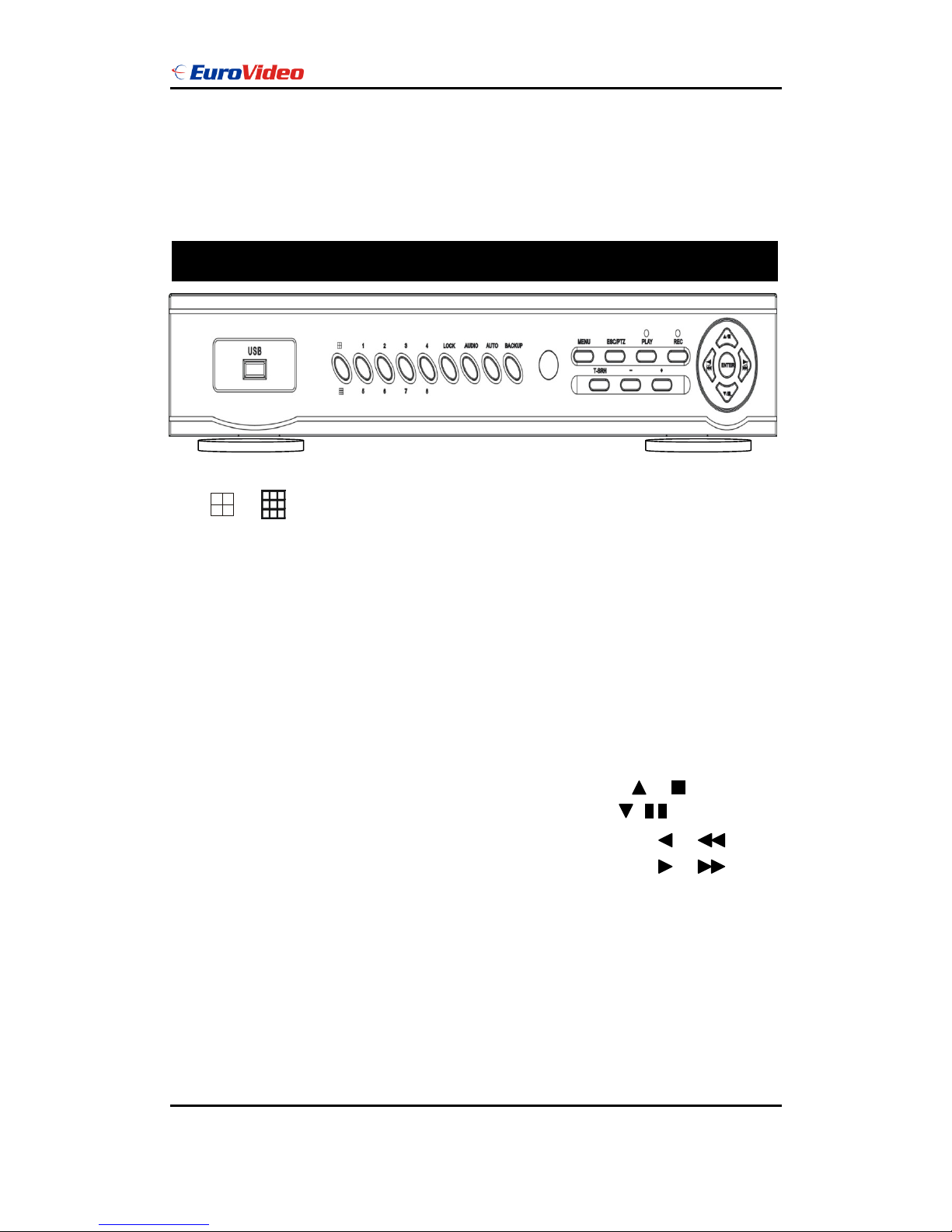
1. / : Quad screen mode button
2. CHANNEL 1 / 5 : Channel 1 / 5 full screen button
3. CHANNEL 2 / 6 : Channel 2 / 6 full screen button
4. CHANNEL 3 / 7 : Channel 3 / 7 full screen button
5. CHANNEL 4 / 8 : Channel 4 / 8 full screen button
6. LOCK : Press this button to Key Lock function
7. AUDIO : Audio on or off button
8. AUTO : Auto sequence mode
9. BACKUP : Image backup button
10. UP / STOP : Direction button UP / Playback stop button /
11. DOWN / PAUSE : Direction button down / Playback pause / (Step play)
12. REW / LEFT : Reverse playback choose button / play speed /
13. FF / RIGHT : Forward playback choose button / play speed /
14. ENTER : Enter button or value change(+) / Shift mode(S)
15. MENU BUTTON : Press this button to display the menu setup
16. ESC / PTZ : Press this button to exit menu / PTZ mode
17. T-SRH : Press this button to playback time search
18. PLAY BUTTON : Press this button to playback
19. + BUTTON : Increase + values change.
20. REC BUTTON : Press this button to start recording image
FRONT PANEL
User Manual
EVD-08/050A1MJN www.eurovideo-cctv.com
6
21. - BUTTON : Reduce - values change
22. USB 2.0 : Pan Driver slot
*User needs to plug in USB again if ActiveX loaded; image backup or version updated.
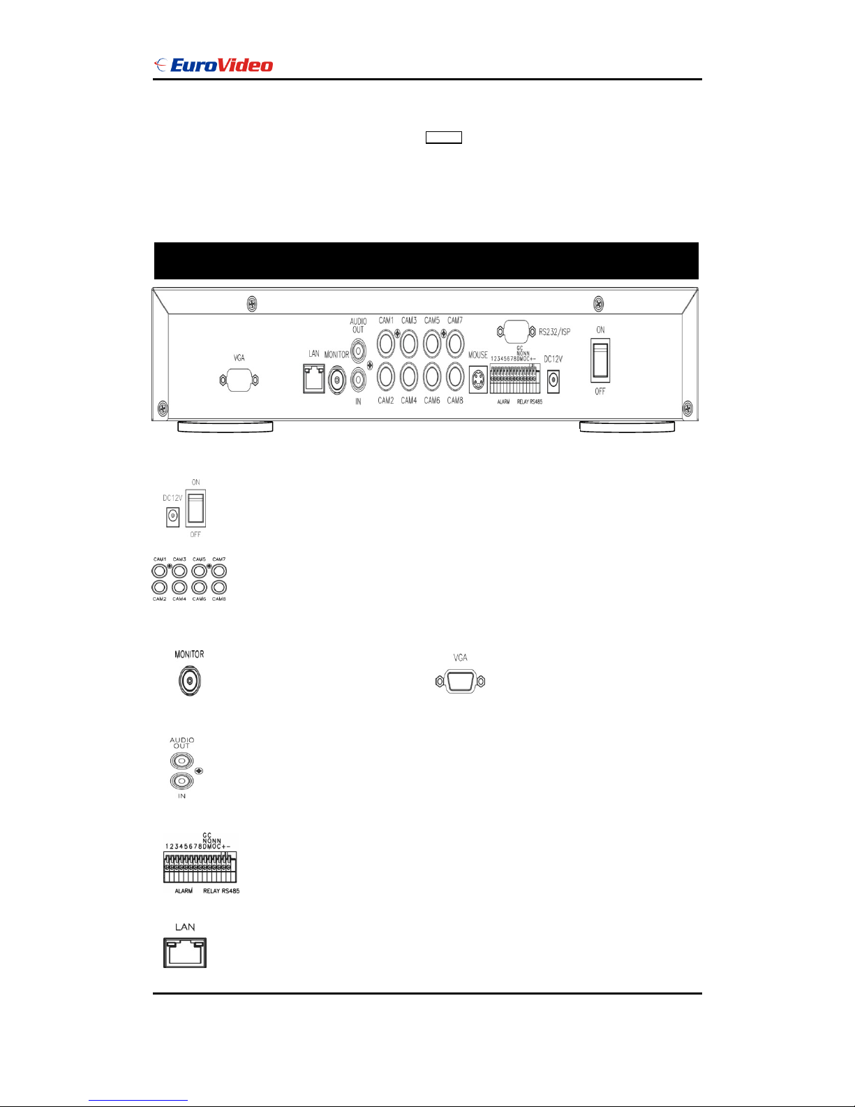
REAR PANEL
Power code in 12V/5A, power switcher (ON / OFF)
Camera 1 ~ 8 input BNC type
Monitor out
Audio channel input x 1 and output x 1
Alarm / Relay / RS 485 connector
VGA out (Optional)
RJ-45 (Network connector)
X

User Manual
EVD-08/050A1MJN www.eurovideo-cctv.com
7
RS232/ISP: Not available
DVR Initialing or detect a new hard disk
PS 2 type mouse connector
Recording icon
Overwrite
Motion
Alarm
Event (Motion / Alarm)
Video loss
Keypad lock * 111111 is the default password
Live screen
**Notice**
Please set HDD to Master if only one
installed.
User Manual
EVD-08/050A1MJN www.eurovideo-cctv.com
8
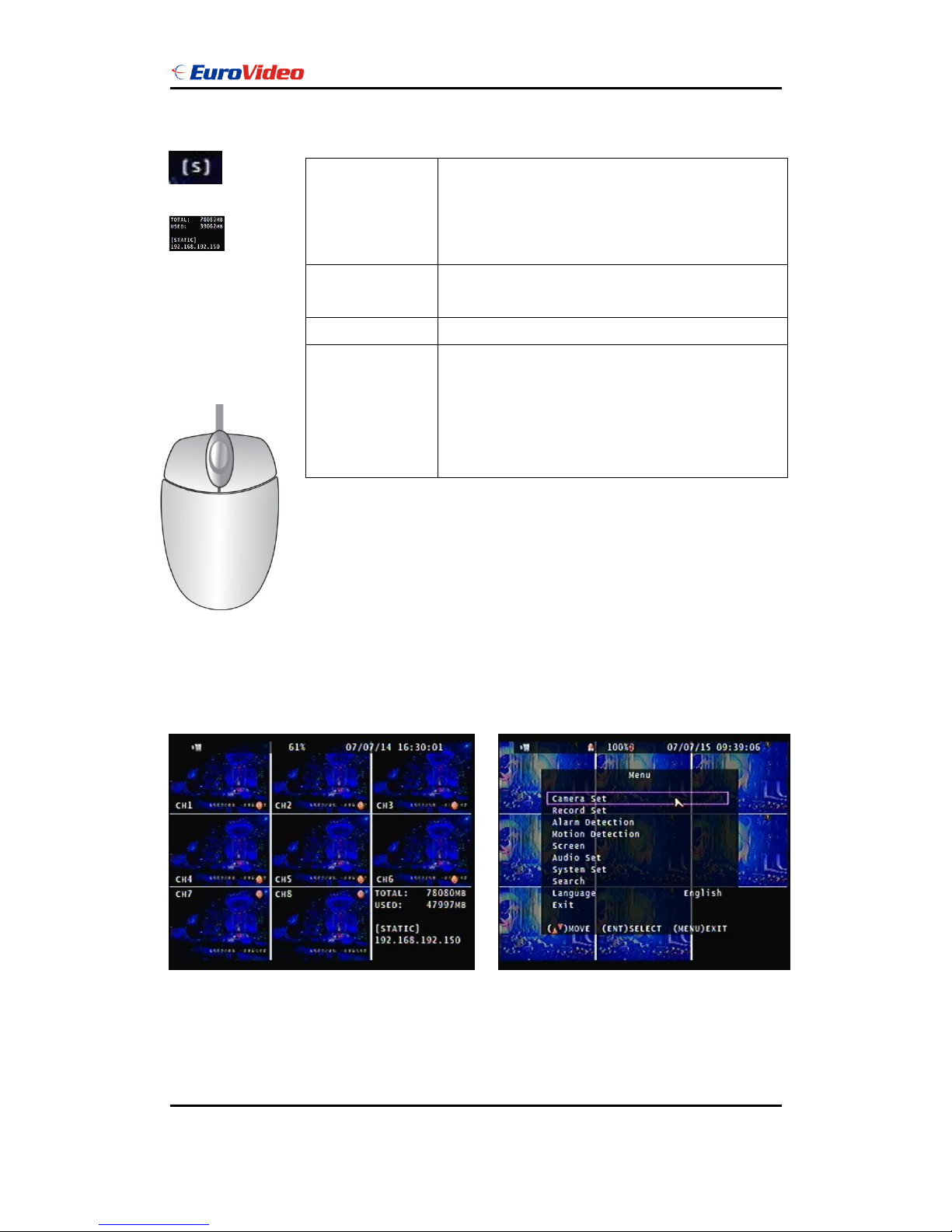
Mouse Control
Operate:
MENU BUTTON : Press MENU button to enter menu setup or exit
○,1 Screen
display
1. Double-click of the left button on desired camera
to full channel
2. Double-click of the left button on desired camera
to 9 split screen
○,3 Menu display
1. One-click of the right button to menu OSD
2. Back to last OSD page
○,2 None
No function
○,1 Select
1. One-click on the item of OSD
2. One-click on the value of item
3. One-click on the Exit to quit and save menu
4. From right-up to left-below and the set motion
detect area
○,1
○,2
○,3
On live, press Enter button to (Shift) mode + 1; 2; 3 ; 4 switch to 5; 6; 7; 8 full screen.
Hard Disk capacity; Hard Disk capacity used; Network Type and IP address information
User Manual
EVD-08/050A1MJN www.eurovideo-cctv.com
9
ESC / PTZ : Press ESC button to exit menu / To PTZ control mode
ENTER BUTTON : Press Enter button to confirm set or value change(+) / Shift mode
DIRECTION BUTTON : MENU item select
+ BUTTON : Increase + values change
- BUTTON : Reduce - values change
BACKUP : To backup mode
( ) MOVE (ENT) SELECT (MENU) EXIT
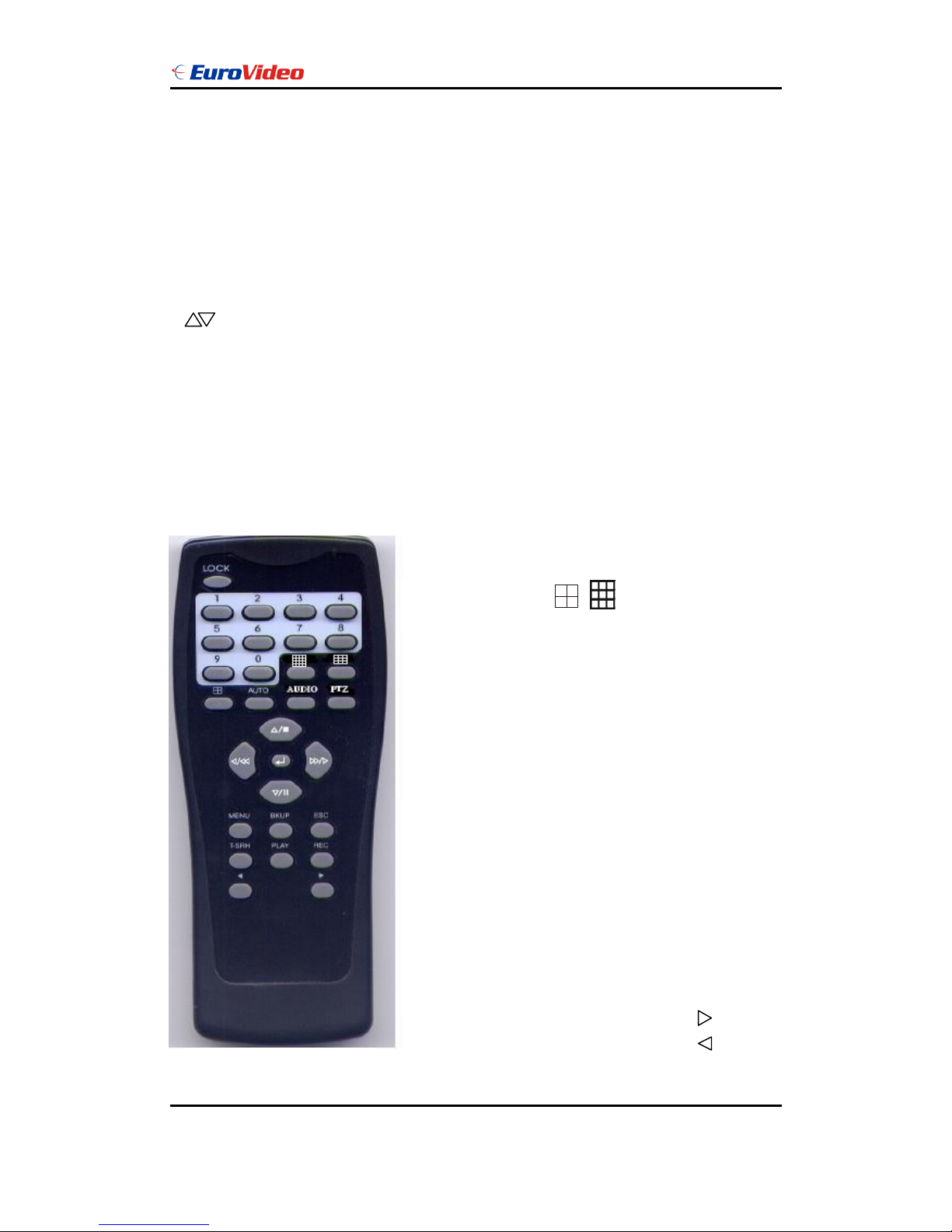
Remote controller (Optional):
The key on the remote controller function control is same as the front keypad of the unit.
User please operate according to the DVR model that you purchased
Number : Channel select 1 ~ 8
UP / STOP : Direction button UP / Playback stop button
REW : Reverse playback choose button
DOWN / PAUSE : Direction button down / Playback pause
FF : Forward playback choose button
ENTER : Enter button or value change
MENU BUTTON : Press this button to display the menu setup
BKUP : Image backup button
ESC : Press this button to exit menu
T-SRH : Press this button to playback time search
PLAY : Press this button to playback
REC BUTTON : Press this button to start recording image
+ BUTTON : Increase + values change
- BUTTON : Reduce - values change
Quad / Split screen
Auto : Channel sequence
Audio : Audio on / off
PTZ : To PTZ mode
User Manual
EVD-08/050A1MJN www.eurovideo-cctv.com
10
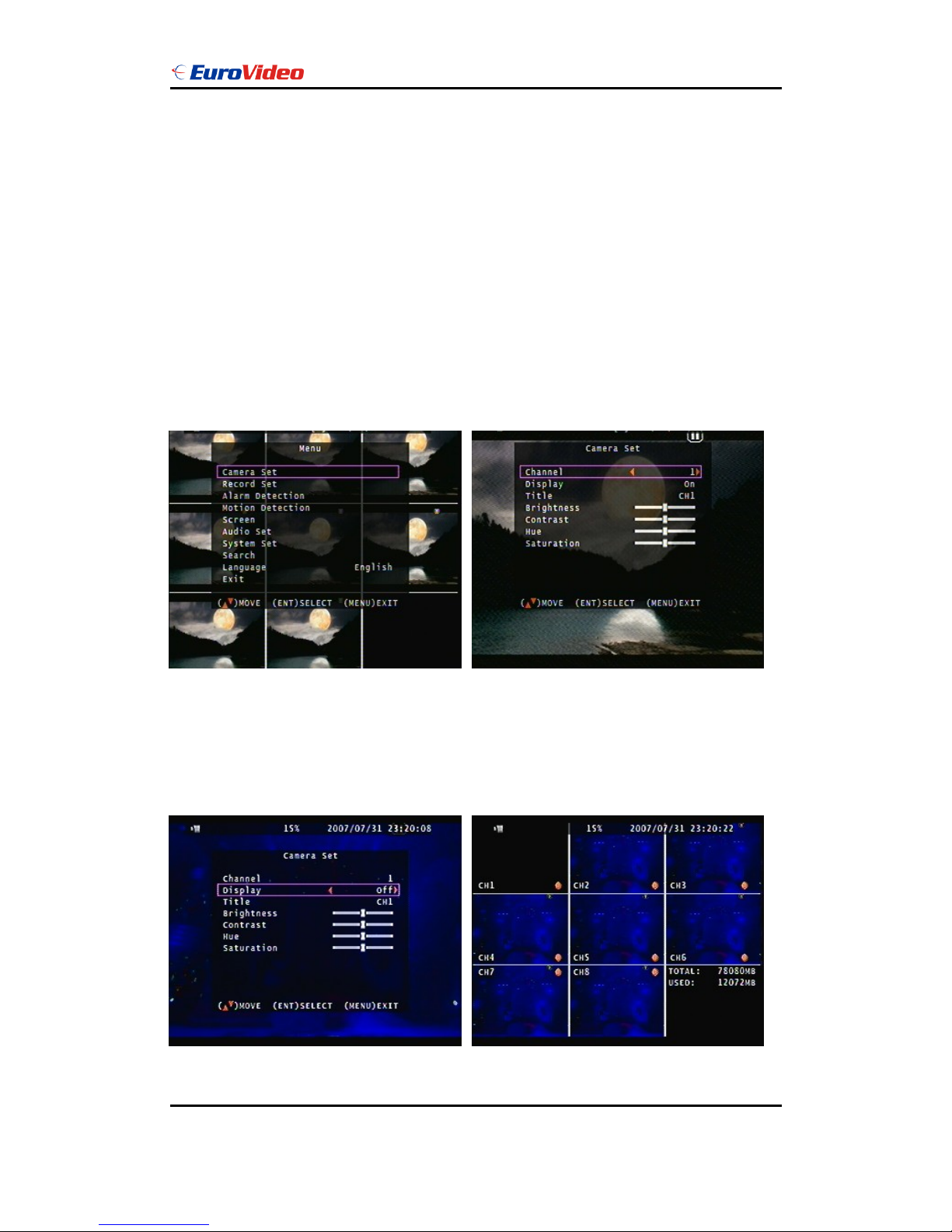
Main MENU – Camera Set
Right adjustment of each element will increase picture quarterly displayed. We recommend
you to adjust each element of cameras and monitor to be connected to the DVR unit.
Main MENU – Camera Set – Display (Channel mask, but it still do recording.)
User Manual
EVD-08/050A1MJN www.eurovideo-cctv.com
11
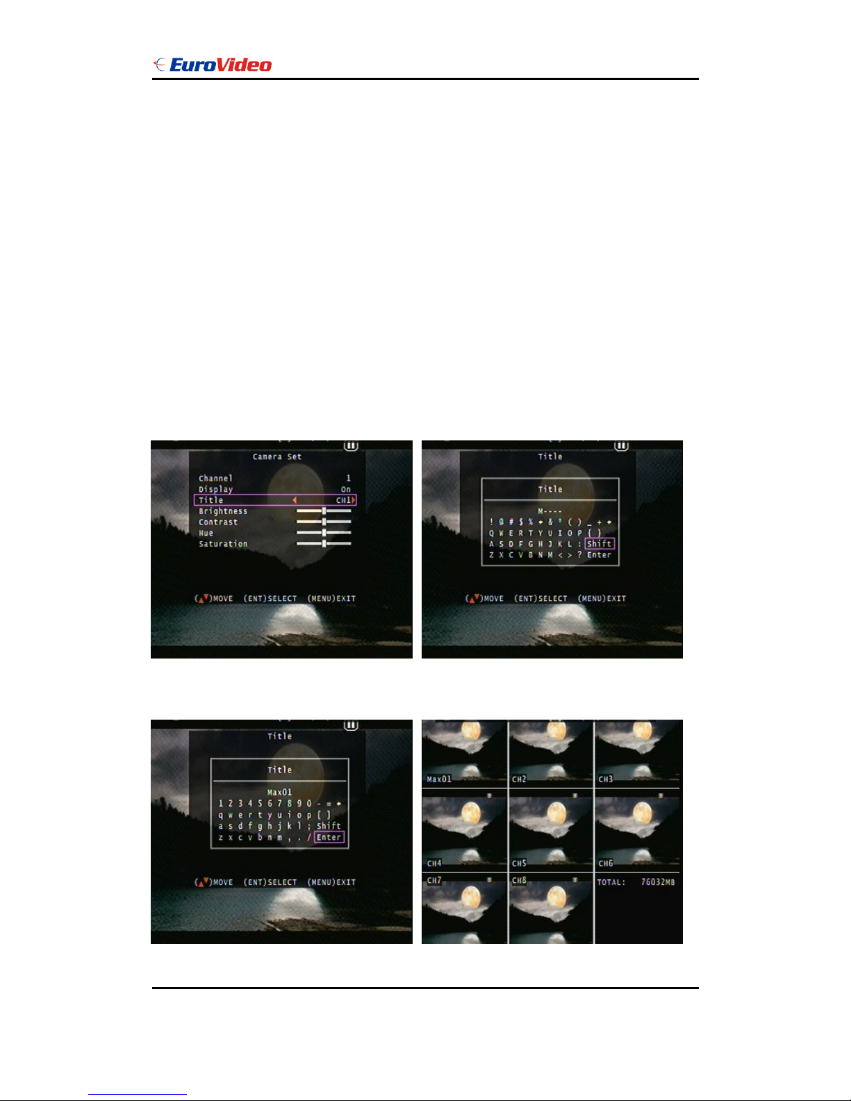
Main MENU – Camera Set – Title
Camera title setup function allows 5 characters for each channel.
Select Shift to next page and then Enter to confirm camera title.
User Manual
EVD-08/050A1MJN www.eurovideo-cctv.com
12
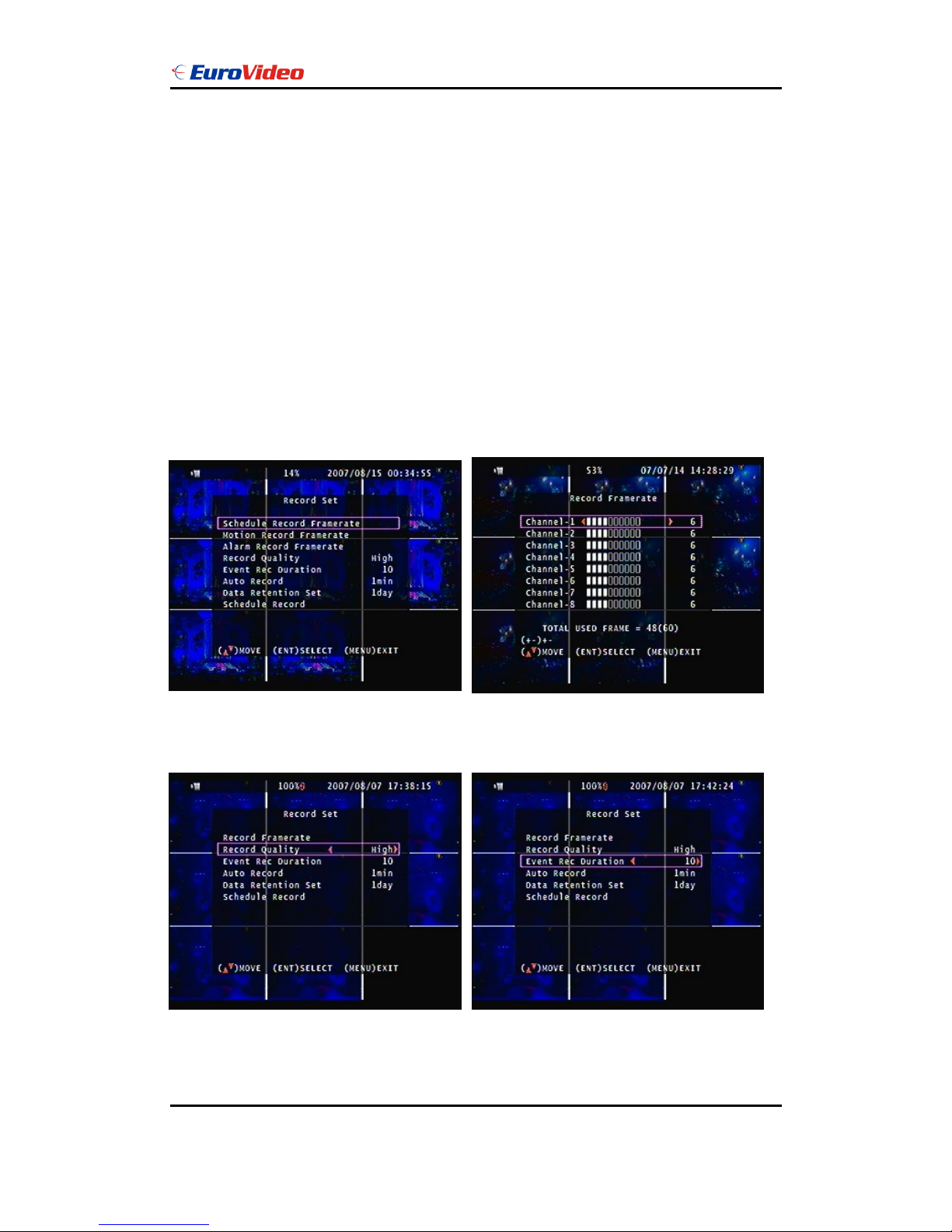
Main Menu – Record Set Record Set – Record Framerate
Record Set – Record Quality Record Set – Event Rec Duration
High / Normal / Low 5 / 10 / 15 / 20 / 25 / 30
Record Set – Auto Record Record Set - Data Retention Set
After 1 ~ 8 minutes, auto start to record 1 ~ 15 days
User Manual
EVD-08/050A1MJN www.eurovideo-cctv.com
13
if no operation.
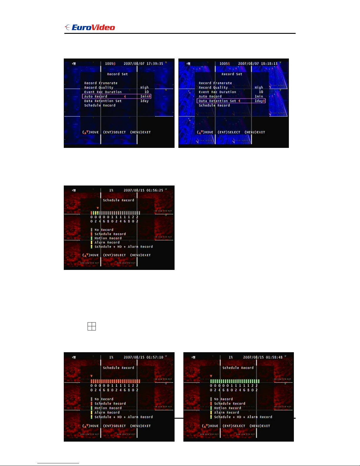
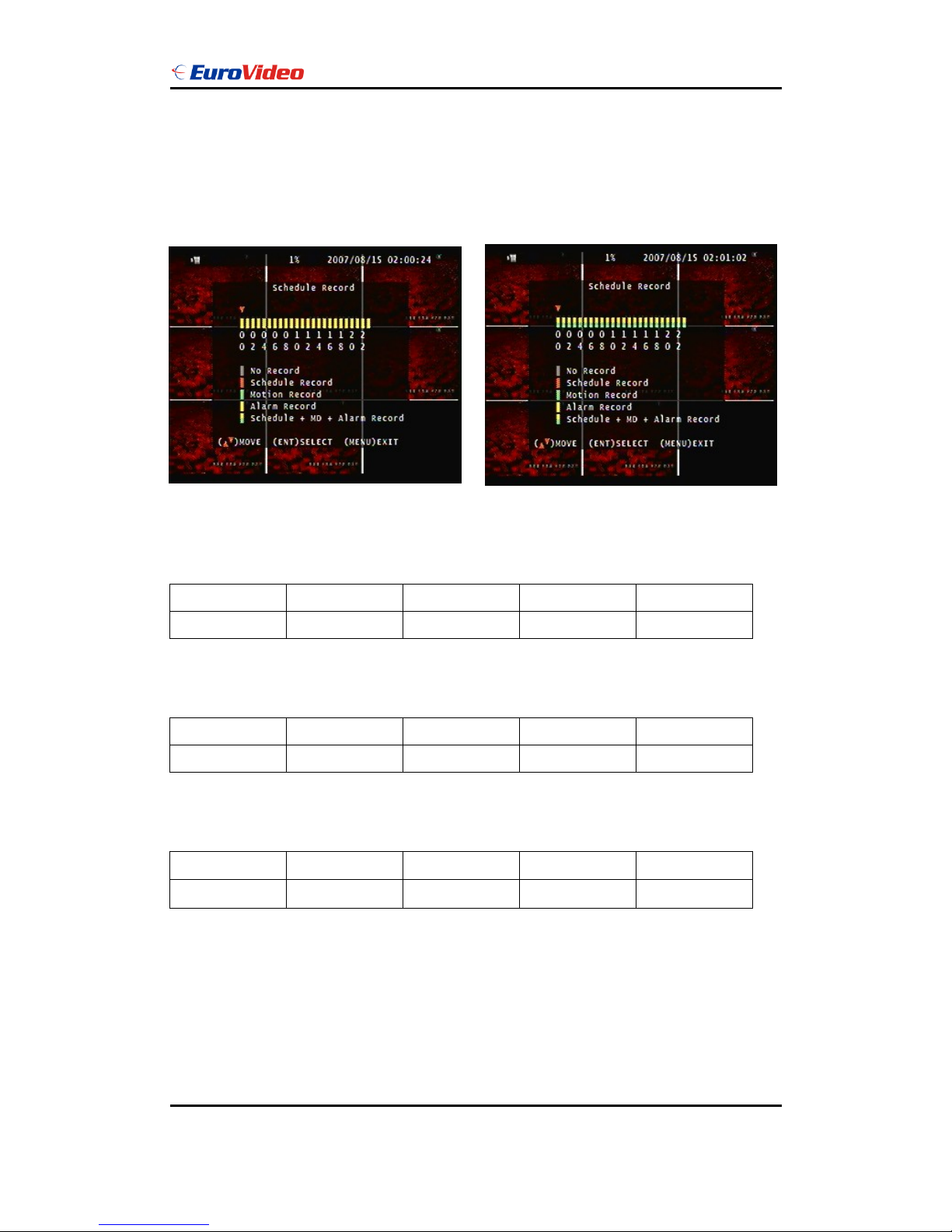
Record Set – Schedule Record
Notice:
1. Each channel has own frame rate adjustment of each recording mode.
2. In 24 hours, user can adjust each channel frame rate of different record mode. Such as
schedule, motion detection, and alarm record more.
3. Press button to change different of record modes.
1. Schedule record mode 2. Motion record mode
User Manual
EVD-08/050A1MJN www.eurovideo-cctv.com
14
3. Alarm record mode 4. Motion + Alarm + Schedule record mode
Record Time Table: 80GB HD
Record Quality: Low. Average: 5 KB;
REC FPS
60
30
15
10
REC Hour
72
148
296
444
Record Quality: Normal. Average 10 KB;
REC FPS
60
30
15
10
REC Hour
36
74
148
222
Record Quality: High. Average 20 KB;
REC FPS
60
30
15
10
REC Hour
18
37
74
111
Actual recording time is base on live environment. This table is only for reference.
20 K x 30 (frame rate) x 60 (mins) x 60 (secs) = 2160000 K = 2160 M / hr
2160 M / hr x 24 = 51840000 K = 51840 M = 51.84 G / (1 Day)
Please format hard disk before starting recording after all the HDD installation

User Manual
EVD-08/050A1MJN www.eurovideo-cctv.com
15
Hard disk compatible table
IDE
Seagate
Hitachi
WD(AAJB)
Status
80 ~ 750 GB OK
80 ~ 750 GB OK
80 ~ 750 GB OK
SATA
Hitachi
WD(AAJB)
Seagate
Status
80 ~ 750 GB OK
80 ~ 750 GB OK
Fail
Main Menu – Alarm Detection
Alarm Signal type depends on Alarm Sensor polarity define on NO (N/Open) or NC (N/Close)
mode. Alarm POP UP: Event channel jump to full screen when alarm triggered. 9 Split screen
with the alarm symbol if there is more than two cameras triggered.
Door closed
Door open
 Loading...