

Euro Video EVC-TP-SO453ARW, EVC-TP-SO448AN Instruction Manual
INSTRUCTION MANUAL
EVC-TP-SO453ARW,
EVC-TP-SO448AN
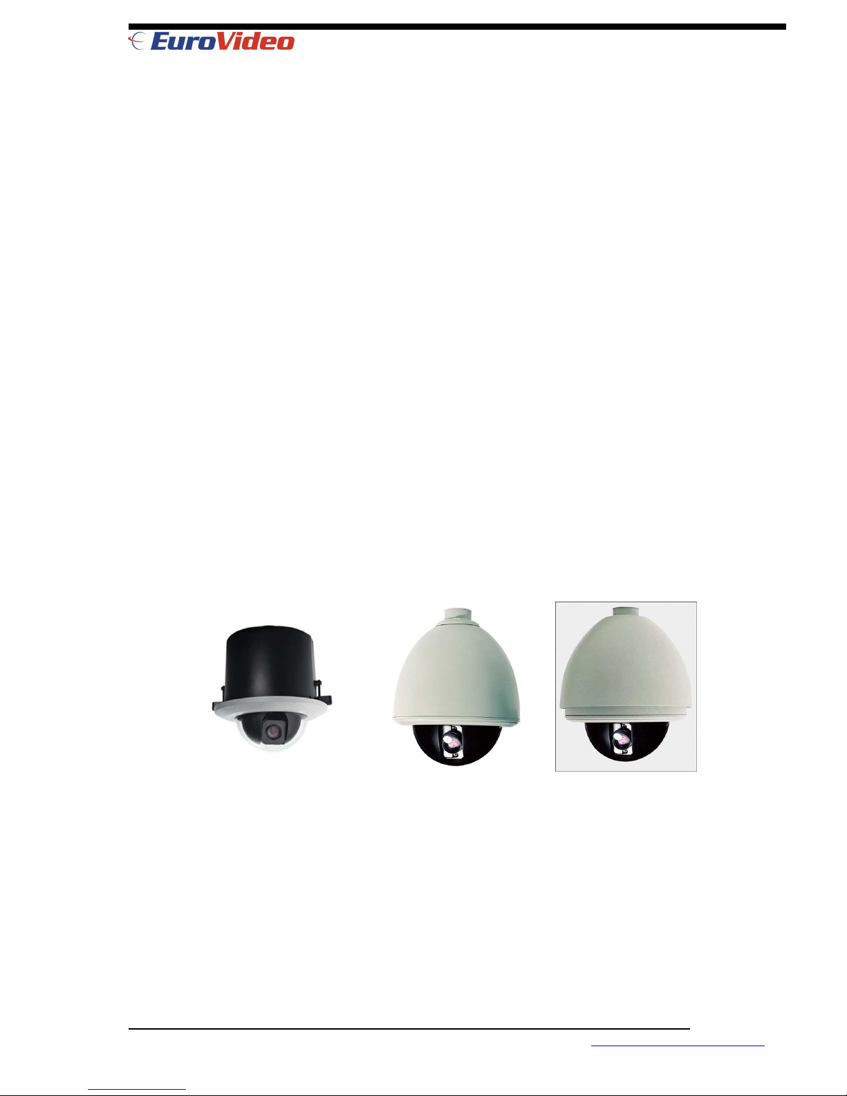
(Indoor Embedded) (Indoor Use) (Outdoor Use)
Note:
• Read this manual carefully before installation
and operation. Keep it handy for later
reference.
•
This manual covers installation and
operation of 3 type of speed dome
embedded, indoor and outdoor
EVC-TP-SO453ARW, EVC-TP-SO448AN
www.eurovideo-cctv.com
INSTRUCTION
MANUAL

INSTRUCTION MANUAL
CONTENTS
FEATURES…………….………………….……….…3
DECLARATION……….………….….……………….5
■Precaution.………….……………………..…5
■Warnings…………….…………………….....5
INSTALLATION PREPARATION……………….....5
■Tool List….……….............………….……...6
■Cables…………………………………………6
■Dip Switch Setting.…….…….......………...6
MOUNT TYPE………………...…..……….......…….7
■In-ceiling Mount ........……………..……....7
■Wall Mount..........…………………………..7
■Corner Mount.........………………………..7
■Pole Mount ..........………………………….7
■Pendent Mount..........……………………..7
INSTALLATION GUIDE.......……………………….8
■In-ceiling Mount ........……………..……....8
■Wall Mount..........…………………………..10
■Corner Mount.........………………………..12
■Pole Mount ..........………………………….14
■Pendent Mount..........……………………..16
SYSTEM CONNECTION.....………………………19
OPERATION INSTRUCTION.........……………...20
■Boot-up Screen ........………………..……20
■Access Main Menu ……………………….21
MENU OPERATION......……………………....…..22
■Selecting Items..........…………………….22
■Changing Items ...........…………………..22
■Editing Titles ...........……………………...22
SYSTEM INFO ...........…………………………….23
■Site info…………...........………………….23
■Display Setup…………...........…………..24
■Boot-up Screen…...........…………………24
■Password …………..........………………..24
■Set Default ................…………………….25
■System Reboot …………………………..25
LENS PARAMETERS ...........…………………….26
■Zoom Speed...........……………………….26
■Digital Zoom...........……………………….26
■Joystick AF/AI.......…………………….....26
■AF Resume Time………………………….26
■AI Resume Time…………………………..27
■Iris ALC ..........…………………………….27
■Iris PLC ..........…………………………….27
■Day/Night ...........………………………….27
CAMERA PARAMETERS........……………..32
■Frame Limit…...........………………..28
■Shutter...........………………………..28
■Exposure ...........…………………….28
■Preset Freeze...........………………..28
■White Balance .……….……….........29
■BLC Mode...........………….……..…..29
PAN/TILT PARAMETERS..........…………...30
■Auto Stop Time..........……………….30
■Speed Amplify ..........………………..30
■Proportional P/T ...........……………30
■Set North ..........……………………...30
AUTO RUNNING.……..........………………...31
■Preset...........………………………….31
■Tour...........…………………………….32
■Pattern...........…………………………33
■Cruise……...........……………………..34
■Zone...........…………………………….35
■Park Time...... ....……….....………....36
■Park Action........ ....………..…..…....36
PRIVACY MASK…............…………………..37
ALARM …………...........……………………..38
APPENDIX I: DIP SWITCH SETTING..........39
■Dip Switch Position ..........………….39
■Protocol and Baud Rate Setting .....39
■Dome Address Setting.........………..40
■Address Setting Chart ..........……….40
■Resistor Jumper Setting ..........…...43
■Alarm Output Method Setting.........43
APPENDIX II: WIRE DIAMETER &
TRANSMISSION CHART……………. 44
APPENDIX III: RS485 BUS BASIC KNOWLEDGE
..........………………….45
APPENDIX IV: TROUBLE SHOOTING ........47
APPENDIX V: LIGHTNING & SURGE
PROTECTION………………………..…48
APPENDIX VI:
WARRANTY.........………………..49
EVC-TP-SO453ARW, EVC-TP-SO448AN
www.eurovideo-cctv.com
FEATURES
Product Features
Multiple Integrated Camera/Optics Packages
Graceful outlook, Vandal proof available
System preheat in low temperature environment
Programmable Multi-protocol
360° continuous pan, 180° Tilt “Auto Flip”
4 tours(27 presets/tour), 4 patterns, 4 cruise
8 Privacy Mask, 8 titled zones
Port for Software up-grade
Built-in Alarm, 7 Inputs/2 Outputs
Built-in Surge and Lightning Protection
Speed Amplify to fit different control keyboard
Auto Running Memory Against Power Outage
Auto Running Resume after Manual Operation
On-Screen display for compass and tilt angle,
System and environment temperature, fan status
Dome Drive Unit
360° continuous pan, 180°Tilt “Auto Flip”
Discreet Liner with Sealed Fixed Bubble
220 presets, ±0.1° preset accuracy
300°/s Pan/Tilt Preset Speed
4 tours max. 27 presets/tour
4 patterns, 4 cruises, 8 titled zones
8 privacy mask
OSD Menu password protection
Built-in alarm, 7 input/2 output
Multiple RS485 protocol/Coaxial
Locations of Labels and On-Screen Displays
Software Up-gradable
FIFO alarm priority levels
Alarm driven Pattern, preset etc.
Position Resume After Alarm
Variable Cruise Speed 0.1-150°/sec
OSD Menu for Programmable Functions
Proportional Pan/Tilt Speed
Vertical Tilt Unobstructed 0° to -90°
Auto Running Memory Against Power Outage
Auto Running Resume after Manual Operation
System preheat before camera power on
On-Screen display for compass and tilt angle,
System and environment temperature, fan status
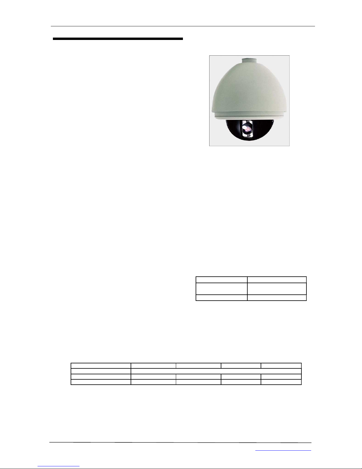
Environment
Operating Temperature
Model Absolute Max Sustained Max Absolute Min Sustained Min
In-Ceiling Indoor 32° to 122°F (0° to 50°C)
Standard Pendant 113°F (45°C) 95°F (35°C) -4°F (-20°C) 14°F (-10°C)
Environmental Mount 140°F (60°C) 122°F (50°C) -60°F (- 51°C) -50°F (-45°C)
Note:
1. Assume no wind chill factor
2. Prevents icing at sustained minimum of -50°F (-45°C)
3. De-ices 0.1 inch (2.5 mm) within 3 hours after power-up
TECHNICAL SPECIFICATIONS
EVC-TP-SO453ARW, EVC-TP-SO448AN 3 www.eurovideo-cctv.com
Electrical
Input Voltage 16-30 VAC; 24 VAC nominal
Input Power 10 VA nominal (w/o heater)
45 VA nominal (with heater)
Fuse 1.25A
Auxiliary Outputs 2 Alarm Inputs 7
Built-in Surge Protection
Limited Lightning Protection
General
Construction
Back Box & Housing Die-cast Aluminum
Dome Drive Aluminum, thermo
plastic
Bubble Acrylic/Poly Carbon

Camera/Optics
Image Sensor 1/4” Super
HAD
1/4” Super
HAD
1/4” Exview
HAD
1/4” Super
HAD
1/4” Super
HAD
Effective
pixels
440k(PAL)
380k(NTSC)
440k(PAL)
380k(NTSC)
420k(PAL)
360k(NTSC)
440k(PAL)
380k(NTSC)
440k(PAL)
380k(NTSC)
Resolution
470TVL 470TVL 470TVL/550TVL 470TVL 470TVL
Lens
22X
f=4~88mm
22X
f=4~88
23X
f=3.6~82.8mm
F1.6~F3.7
18X
f=4.1~73.8mm
F1.4~F3.0
27X
f=3.6~98
Digital Zoom
22X12 22X12 23X10 18X12 27X10
Zoom Speed
3.9s~6.3s 3.9s~6.3s 3.9s~6.3s 3.9s~6.3s 3.9s~6.3s
Angle of View
47°~2.2° 47°~2.2° 54°~2.5° 48°~2.7° 47°~3.0°
Sync system
Internal/external
Min. Illumination
0.9Lux 0.02Lux 0.013Lux 0.7Lux 0.01Lux
S/N Ratio
>50db
Iris
Auto/Manual
White Balance
Auto/Manual
Gain
Auto
AE Control
Auto/Manual
BLC
On/Off
Privacy Mask
No Yes Yes No No
Focusing system
Auto/Manual
Video Output
1.0±0.2Vp-p
Accessories
Mounting
Wall mount bracket
Pendant mount accessory
Corner mount accessory
Pole mount accessory
Heating
Outside temperature sensor
Transmitting & Controlling
Active or Passive Twisted Pair Connector
Manchester Code/RS485 converter
EVC-TP-SO453ARW, EVC-TP-SO448AN 4
www.eurovideo-cctv.com

DECLARATION
This equipment generates, uses, and can radiate
radio frequency energy and, if not installed and
used in accordance with the instruction manual,
may cause harmful interference to radio
communications. Operation of this equipment in
a residential area is likely to cause harmful
interference in which case the user will be
required to correct the interference at the user’s
own expense.
■ PREC AUTIONS:
♦
Only qualified and experienced person
can carry out the installation. In many
countries and areas licensed personnel
is required
♦ Always take safety codes into
consideration during installation.
♦ Use reliable tools only, poor quality
tools may cause damage to both human
and property
♦
Check the strength of all item onsite
that are related to installation in
advance. It is recommended that the
stand of dome be 8 times stronger than
the weight of the dome and its
accessories.
♦ Keep all the original dome package
materials in case of future repacking
and transportation.
♦
Choose and install speed dome
according to environment requirement
(Refer to the Product Features). This
product conforms to IP66 standard as
specified in “Housing Protection
Classification (IP code)”.
■ WARNINGS:
♦
Avoid installing this speed dome in
hazardous places where inflammable or
explosive materials are stored or used.
♦ Indoor dome is not designed for
outdoor environment.
♦ This speed dome runs on 24v AC.
♦ Connect to power only after completing
installation.
♦ Disassemble can only be carried out by
qualified personnel.
♦ Use soft towel to clean the down cover
when necessary. Avoid using caustic
detergent.
♦ Avoid aiming camera to strong light.
EVC-TP-SO453ARW, EVC-TP-SO448AN 5 www.eurovideo-cctv.com
INSTALLATION
PREPATATION
■TOOL LIST:
Following tools may be needed for the
installation:
♦ Screws and nuts
♦ Philips screw driver
♦ Standard screw driver
♦ Wire scissors
♦ Ladder
♦ Drill
♦ Saw.
■CABLE:
♦ Video Coaxial Cable
♦
75ΩΩΩΩ impedance,
♦ Solid copper wire,
♦ 95% braided copper shield.
Check the max transmission distance referring to
the chart below.
Model Distance
RG 59/U 750ft(229m)
RG 6/U 1,000ft(305m)
RG 16/U 1,5000ft(457m)
♦ RS485 Cable
♦ 0.56mm (24AWG) twisted pair wire
■DIP SWITCH SETTING
See appendix I :
♦ Protocol and Baud rate
♦
Dome address
♦ Video cable type
♦ Resistor jumper
♦ Alarm output method
EVC-TP-SO453ARW, EVC-TP-SO448AN 6
www.eurovideo-cctv.com

MOUNT TYPE
■ IN-CEILING MOUNT
■ WALL MOUNT
■ CORNER MOUNT
■ POLE MOUNT
■ PENDANT MOUNT
EVC-TP-SO453ARW, EVC-TP-SO448AN
- 7-
www.eurovideo-
cctv.com
INSTALLATION GUIDE
■ IN-CEILING MOUNT
Maximum thickness of the ceiling is 42mm and the
ceiling should be able to hold 8 times of the weight of
the speed dome. More than 20cm of clear space is
needed above the ceiling.
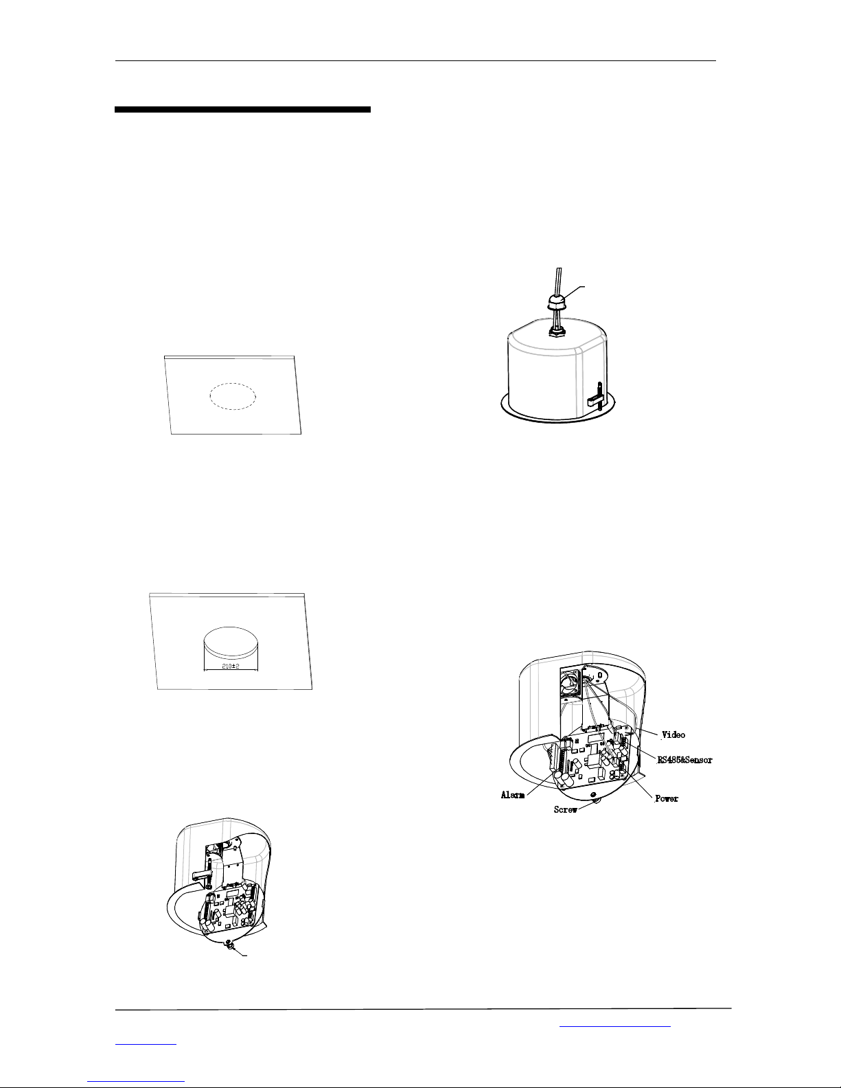
1. Mark the hole on ceiling.
Mark a φφφφ225 mm circle on the proper position of
the ceiling using the accessory paper sheet
2. Make the hole.
Cut the hole with proper tool. Make sure the
tolerance is less than +2mm.
3. Unfasten the circuit board.
Unscrew the screw to open the circuit board on
connection board.
Scr ew
4. Conduct cables.
Prepare wiring and then put Power/RS485/ Video
cables through waterproof connector on the top of
housing. Turn the connector into the top hole of
the housing
Wat er - proof
Connect or
5. Connect cables.
Plug cables into corresponding sockets on circuit
board. When finished, fix the circuit board back
and turn on the power. The red LED will light.
Turn off the power after checking.
NOTE: There are signs for each port. Fix cables as
picture shows. Make sure power is off before
connecting.
EVC-TP-SO453ARW, EVC-TP-SO448AN
- 8-
www.eurovideo-
cctv.com
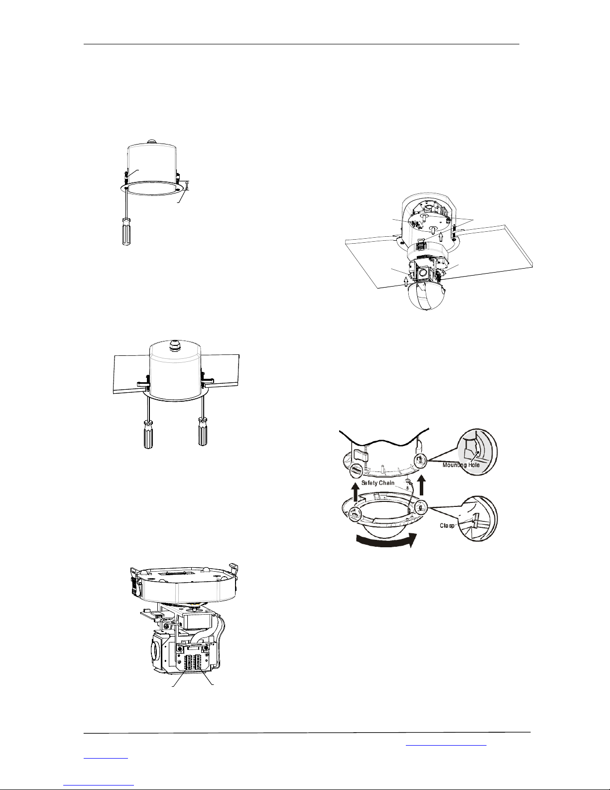
6. Adjust clips.
Adjust the height of the three mounting clips.
Swing the three mounting clips to adhere to
housing.
Cei l i ng Thi ckness
Mount i ng Cl i p
7. Install housing.
Push housing into ceiling and let the clips stretch
out. Finally, screw the three clips to tighten the
housing
8. Set dome ID, baud rate and protocol.
Set dome ID, bard rate and protocol by
configuring DIP switches (see APPENDIX I ).
NOTE: Remove the packing sponges.
SW 1
SW 2
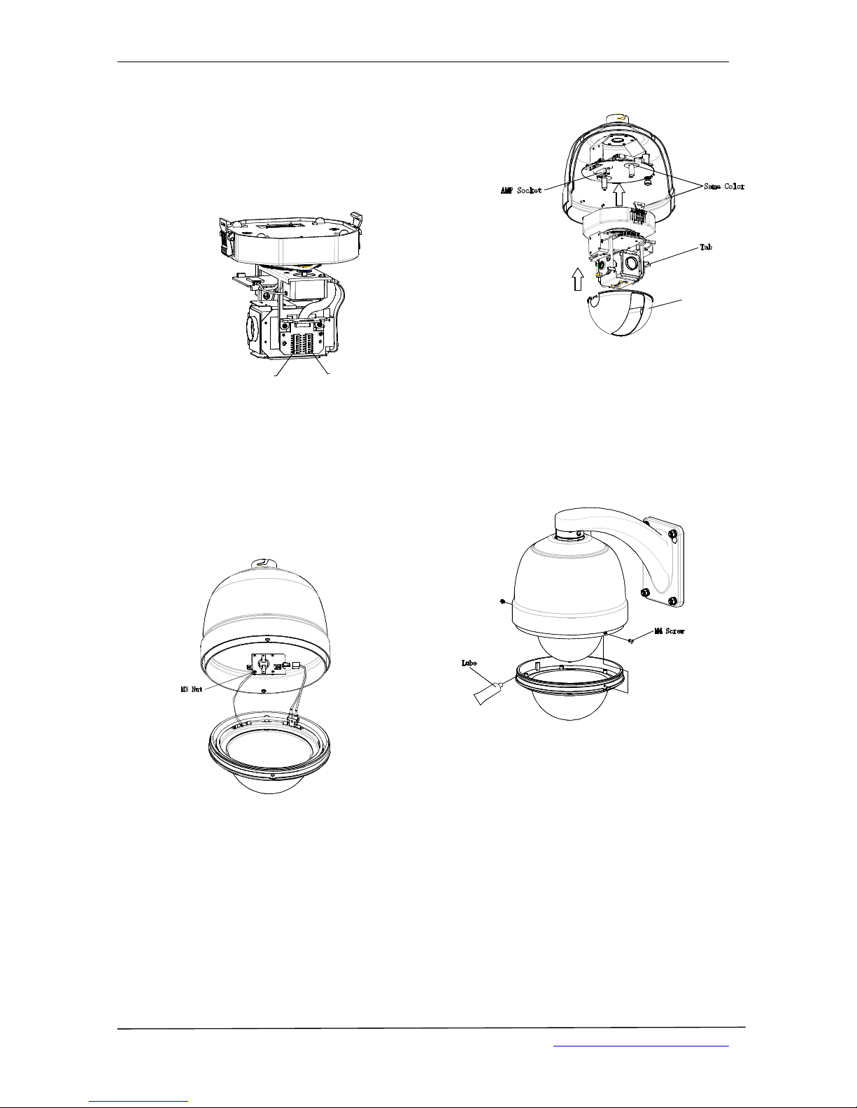
9. Install Pan/Tilt Module.
Push the black liner into the two tabs. Install the
pan/tilt module with two clips, match color of
AMP sockets. Gently push the module upward
until hearing two clicks.
NOTE: Remove the lens cover
Sam e Color
AM P Socket
Tab
Tab
10. Install down cover.
Fasten the safety chain on housing. Align clasps
and mounting holes then turn clock-wise.
NOTE: Let the safety chain inside the arc groove
of the down cover, otherwise it may scratch the
lens.
EVC-TP-SO453ARW, EVC-TP-SO448AN
- 9-
www.eurovideo-
cctv.com
■WALLMOUNT
Check carefully to make sure the wall is firm and does
not peel off. It is required that the wall can withstand 8
times weight of the dome set.
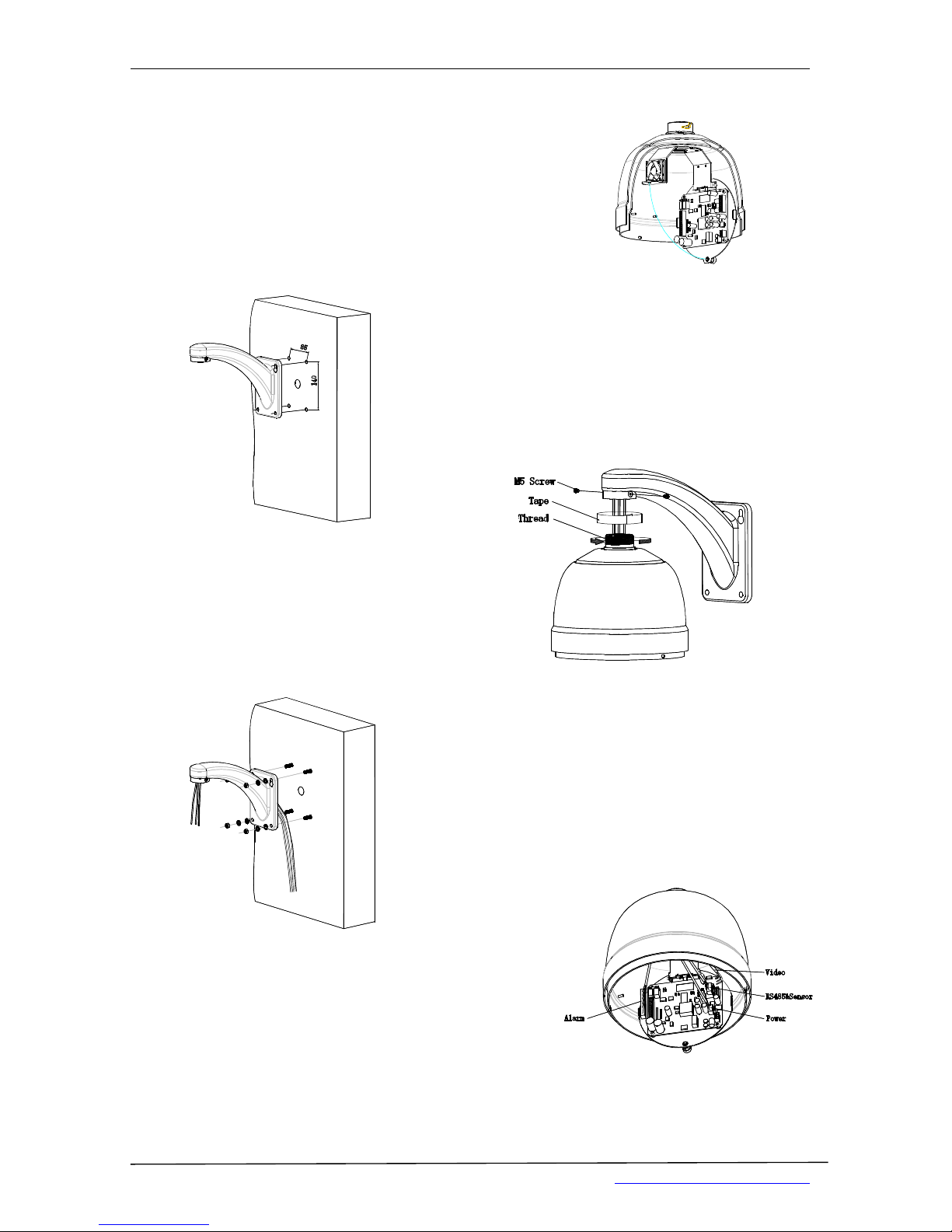
1. Mark mounting position
Use bracket to mark the mounting position on wall.
2. Install bracket.
Conduct all cables through the hole of bracket, and fix
bracket on the wall.
NOTE: Put cables through the wall or aside the
bracket.
3.
Release the connection board.
Unscrew to release the circuit board on connection
board.
4. Install housing
Conduct cables through the hole on top of the housing.
Align the fast connector to bracket and fix with 2 M5
screws.
NOTE: Apply water-proof tape to the thread in the
case of outdoor dome
5. Connect cables.
Plug cables into corresponding sockets on circuit
board. Reinstall the circuit board and turn on the
power. The red LED is on if connections are correct.
Turn off the power after checking.
NOTE: Names of the interfaces are marked on
terminal block or PCB. Connect cables as picture
shows. Make sure power is off before connecting.
EVC-TP-SO453ARW, EVC-TP-SO448AN
www.eurovideo-cctv.com
-10-
6. Set dome ID, baud rate and protocol.
Set dome ID, bard rate and protocol by configuring
DIP switches (see APPENDIX I ). Remove the packing
sponges.
SW 1
SW 2
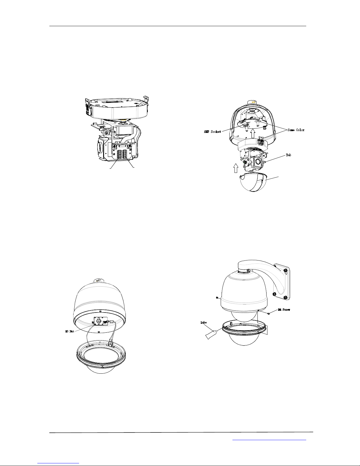
7. Down cover preliminary installation.
Attach the safety chain with a M3 nut as picture shows.
NOTE: Plug the heater wiring into socket on heater in
the case of outdoor dome
8. Install black liner and Pan/Tilt Module.
Push the black liner into the two tabs. Install the
pan/tilt module with two clips, match color of AMP
sockets. Gently push the module upward until hearing
the click.
NOTE: Remove the lens cover
Bl ack Li ner
9. Install down cover.
Unscrew the two M4 screw on down cover ring. Push
up the down cover into the housing and then fasten
down cover with two M4 screws.
NOTE: Apply lube to the O-ring in the case of outdoor
dome
EVC-TP-SO453ARW, EVC-TP-SO448AN
www.eurovideo-cctv.com
-11--11-

■CORNER MOUNT
Check carefully to make sure the wall is firm and does
not peel off. It is required that the wall can withstand 8
times weight of the dome set.
1. Mark the fastener positions.
Use the corner mount base as the template to mark
the mounting positions on wall.
2. Install base.
Put Power/RS485/ Video cables through the hole of
corner mount base and use M8 nuts to fasten
corner base on the mounting surface.
NOTE: Put cables through the wall of aside the
corner base
3. Install bracket.
Put cables through the cavity of bracket and fasten
bracket on base
4.
Release the connection circuit board.
Unscrew to release the circuit board on
connection board.
5. Install housing.
Conduct cables through the hole on top of the
housing. Align the fast connector to bracket and fix
with 2 M5 screws
NOTE: Apply water-proof tape to the thread in
the case of outdoor dome
EVC-TP-SO453ARW, EVC-TP-SO448AN
www.eurovideo-cctv.com
-12-

6. Connect cables.
Plug cables into corresponding sockets on circuit
board. Reinstall the circuit board and turn on the
power. The red LED is on if connections are
correct. Turn off the power after checking.
NOTE: Names of the interfaces are marked on
terminal block or PCB. Connect cables as picture
shows. Make sure power is off before connecting
7. Set dome ID, baud rate and protocol.
Set dome ID, bard rate and protocol by
configuring DIP switches (see APPENDIX I).
NOTE: Remove the packing sponge.
SW 1
SW 2
8. Down cover preliminary installation.
Attach the safety chain with a M3 screw as picture
shows.
NOTE: Connect the plug into socket on heater in
the case of outdoor dome
9. Install black liner and Pan/Tilt Module.
Push the black liner into the two tabs. Install the
pan/tilt module with two clips, match color of
AMP sockets. Gently push the module upward
until hearing two clicks.
NOTE: Remove the lens cover.
Bl ack Li ner
10. Install down cover.
Remove the two M4 screws on down cover ring.
Push up the down cover into the housing, and then
fasten down cover with two M4 screws.
NOTE: Apply the lube to the O-ring in the case of
outdoor dome
EVC-TP-SO453ARW, EVC-TP-SO448AN
www.eurovideo-cctv.com
-13--13-
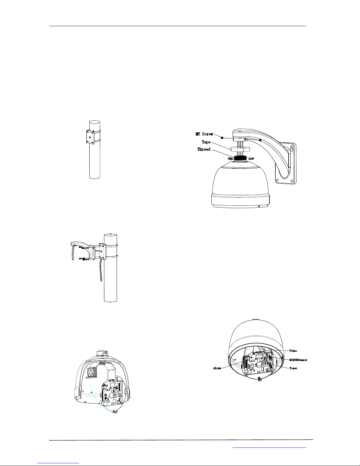
■POLE MOUNT
Pole mount is applicable to installation on pole with
diameter of 130-150mm ( 5.12”~6”)
1. Install base.
Put Power/RS485/ Video cables through the
central hole of the bracket base, and then fix it to
the pole
2. Install bracket.
Put cables through the cavity of bracket and fasten
it on base.
3.
Release the circuit board.
Unscrew to release the circuit board on connection
board.
4. Install housing.
Conduct wirings through the hole on top of the
housing. Align the fast connector to bracket and fix
with 2 M5 screw
NOTE: Apply water-proof tape to the thread in
the case of outdoor dome
5. Connect cables.
Plug cables into corresponding sockets on circuit
board. Reinstall the circuit board and turn on the
power. The red LED is on if connections are
correct. Turn off the power after checking.
NOTE: Names of the interfaces are marked on
terminal block or PCB. Connect cables as picture
shows. Make sure power is off before connecting
EVC-TP-SO453ARW, EVC-TP-SO448AN
www.eurovideo-cctv.com
-14-
6. Set dome ID, baud rate and protocol.
Set dome ID, bard rate and protocol by
configuring DIP switches (see APPENDIX I).
NOTE: Remove the packing sponge.
SW 1
SW 2
7. Down cover preliminary installation.
Attach the safety chain with a M3 screw as picture
shows.
NOTE: Connect the plug into socket on heater in
the case of outdoor dome
8. Install black liner and Pan/Tilt Module.
Push the black liner into the two tabs. Install the
pan/tilt module with two clips, match color of
AMP sockets. Gently push the module upward
until hearing two clicks.
NOTE: Remove the lens cover.
Bl ack Li ner
9. Install down cover.
Unscrew the two M4 screws on down cover ring.
Push up the down cover into the housing and then
fasten down cover with two M4 screws.
NOTE: Apply the lube to the O-ring in the case of
outdoor dome
EVC-TP-SO453ARW, EVC-TP-SO448AN
www.eurovideo-cctv.com
-15--15-
■
PENDENT MOUNT
In case of low ceiling height dome can be mounted
directly into the base flange.
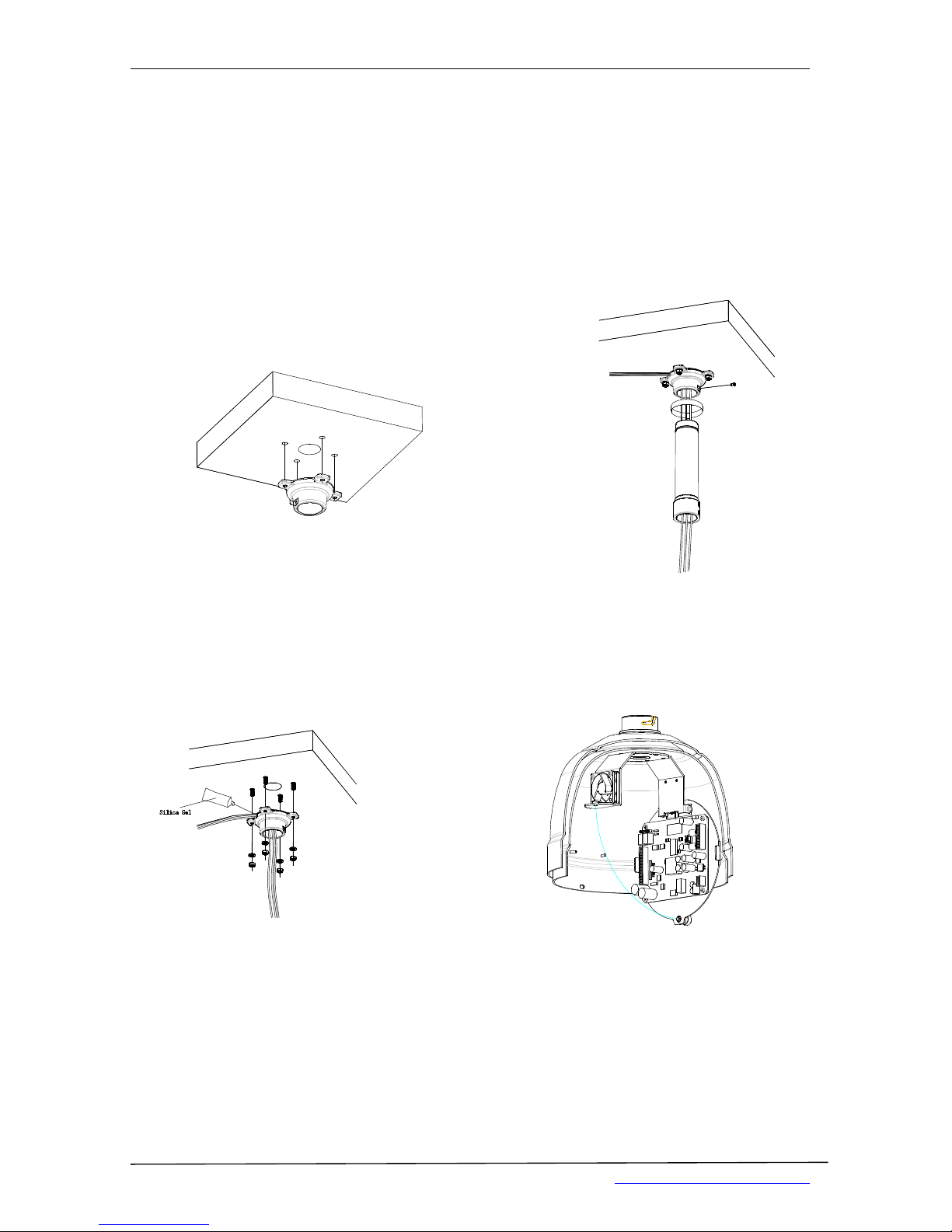
1. Mark the mounting position.
Use the bracket base to mark the fastener positions
on ceiling
2. Install base.
Conduct wirings through the central hole of the
bracket base, and then fix it on ceiling.
NOTE: Put silica gel along the top of bracket base
in the case of outdoor dome.
3. Install suspender.
Conduct wirings through the cavity of suspender,
and then turn the threaded pipe head into the
bracket base and fasten the connection with a M5
screw.
NOTE: Apply water-proof tape to the thread and
put silica gel to the suspender as picture shows in
the case of outdoor doom.
4.
Release the circuit board.
Unscrew to release the circuit board from
connection base
EVC-TP-SO453ARW, EVC-TP-SO448AN
www.eurovideo-cctv.com
-16-
 Loading...