

Eurotron UniGas 3000+, GreenLine 4000, BTU 3000+, EcoLine 4000 Instruction Manual

UUnniiGGaass 33000000++
BBTTUU 33000000++
EEccooLLiinnee 44000000
GGrreeeennLLiinnee 44000000
Handheld Flue Gas Analyzers
Boiler Tuning Units
Instruction Manual MM850402 ed. 08b

Instruction Manual MM850402 ed. 08b
2
INTRODUCTORY NOTE
N
OTE: THIS MANUAL IS VALID FOR INSTRUMENTS WITH SERIAL NUMBER 124012 AND FIRMWARE REV. 1.XX2 OR HIGHER.
This manual includes all the information you need to install, operate and maintain the flue gas analysers
EcoLine 4000, GreenLine 4000, UniGas 3000+ and BTU 3000+ space and theirs accessories.
Eurotron provides the best care and efforts in preparing this book and believes the information in this
publication are accurate. The Eurotron products are subjected to continuous improvement, in order to
pursue the technological leadership; these improvements could require changes to the information of this
book.
Eurotron reserves the right to change any information without notice.
The 3000-4000 series gas analyser uses sophisticated analogical and digital technologies. Any
maintenance operation must be carried out by qualified personnel
ONLY. Eurotron supplies instructions an d
operative procedures for any operation on the instrument. We recommend to contact our technicians for any
necessary questions requirements.
The instrument is supplied by a Ni-MH rechargeable battery pack or by 100, 115, 230V
±
10% 50/60Hz line
supply using the special power supply module provided with the 3000-4000 series.
The instruments are fully tested in conformity with the directive n°89/336/CEE Electromagnetic Compatibility.
Eurotron shall not be liable in any event, technical and publishing error or omissions, for any incidental and
consequential damages, in connection with, or arising out of the use of this book.
The operator must not use this equipment for any other purpose than that stated.
This document is the property of Eurotron and may not be copied or otherwise reproduced, communicated
in anyway to third parties, not stored in any Data Processing System without the express written consent of
Eurotron.
All right reserved
Copyright © 2003, 2008
EUROPEAN Headquarters
Eurotron Instruments SpA
Viale F.lli Casiraghi 409/413
20099 Sesto S. Giovanni (MI)
Tel. : +39-02 24 88 201
FAX: +39-02 24 40 286
Mail: info@eurotron.com
USA Headquarters
E-Instruments Group LLC
172 Middletown Blvd – Suite B201
Langhorne, PA 19047
Tel.: 215 750 1212
FAX: 215 750 1399
Mail: info@einstrumentsgroup.com

Instruction Manual MM850402 ed. 08b
3
TABLE OF CONTENTS
1 GENERAL DESCRIPTION .................................................................................................................. 5
1.1 Ordering Code ......................................................................................................................................................6
1.1.1 EcoLine 4000 ................................................................................................................................................... 6
1.1.2 GreenLine 4000 ...............................................................................................................................................8
1.1.3 Unigas 3000+................................................................................................................................................. 10
1.1.4 BTU 3000+..................................................................................................................................................... 11
1.1.5 Flue gas probes .............................................................................................................................................12
1.2 Specifications...................................................................................................................................................... 12
2 GENERAL.......................................................................................................................................... 15
2.1 Keypad & Display................................................................................................................................................ 15
2.2 Built-In printer ..................................................................................................................................................... 15
2.3 Gas Sampling Probe........................................................................................................................................... 15
2.4 Measuring Sensors ............................................................................................................................................. 15
2.5 Temperature probes ........................................................................................................................................... 15
2.6 Pressure sensor.................................................................................................................................................. 15
2.7 Fuel Technical Data ............................................................................................................................................ 15
2.8 Smoke Measurement.......................................................................................................................................... 16
2.9 Remote Temperature Probe ...............................................................................................................................16
2.10 Ambient CO Probe ......................................................................................................................................... 16
2.11 Natural Gas Probe .........................................................................................................................................16
2.12 Leak test procedure ....................................................................................................................................... 16
2.13 External Low Pressure Sensor (UniGas 3000+) ............................................................................................16
2.14 Burner Pressure Probe .................................................................................................................................. 16
2.15 Ionization Current Probe (option) ................................................................................................................... 16
2.16 Internal Gas Sniffer Probe (option for UniGas 3000+/BTU 3000+) ................................................................ 16
2.17 Pitot tube........................................................................................................................................................ 16
2.18 Calibration Certificate..................................................................................................................................... 17
2.19 Electromagnetic Compatibility........................................................................................................................ 17
3 PHYSICAL DESCRIPTION................................................................................................................ 18
4 PRINCIPLE OF OPERATION............................................................................................................ 19
4.1 Measurement Principle ....................................................................................................................................... 19
4.1.1 Gas Sampling Probe ...................................................................................................................................... 19
4.1.2 Water Trap & Line Filter ................................................................................................................................. 20
4.1.3 Gas Sensors ..................................................................................................................................................20
4.2 Auxiliary Measurements...................................................................................................................................... 21
4.2.1 Temperature Measurements .......................................................................................................................... 21
4.2.2 Pressure and Draft ......................................................................................................................................... 21
4.2.3 Smoke Index Measurement (option) .............................................................................................................. 22
4.2.3.1 Measuring Instruments (option)................................................................................................................. 22
5 RECOMMENDATIONS...................................................................................................................... 23
5.1 Power Supply...................................................................................................................................................... 23
6 CONNECTIONS................................................................................................................................. 24
6.1 Electro-Pneumatic Connections.......................................................................................................................... 24
6.2 Gas Probe Positioning ........................................................................................................................................ 24
6.3 Connecting to a PC............................................................................................................................................. 25
6.3.1 USB installation.............................................................................................................................................. 25
6.3.1.1 Installing the USB driver ............................................................................................................................ 25
7 OPERATIONS.................................................................................................................................... 28
7.1 Basic Operation .................................................................................................................................................. 28
7.1.1 Keyboard........................................................................................................................................................ 28
7.1.2 Display ........................................................................................................................................................... 29
7.1.3 Display adjustment......................................................................................................................................... 29
7.1.4 Numerical Input.............................................................................................................................................. 29
7.1.5 Text input ....................................................................................................................................................... 30
7.1.6 Select from a list............................................................................................................................................. 30

Instruction Manual MM850402 ed. 08b
4
7.2 Flue Gas Analysis ............................................................................................................................................... 31
7.3 Pressure/Draft measurement .............................................................................................................................. 33
7.3.1 Pressure/Draft external probe (option for UniGas3000+)............................................................................... 34
7.3.2 Burner Pressure Measurement ...................................................................................................................... 34
7.4 Smoke Measurement.......................................................................................................................................... 34
7.4.1 Smoke Index data input .................................................................................................................................35
7.5 Combustion Air Temperature (option)................................................................................................................. 35
7.6 Flow/Return Temperature measurement ............................................................................................................ 35
7.7 Gas velocity measurement ................................................................................................................................. 36
7.8 Printing the analysis data.................................................................................................................................... 37
7.8.1 Changing paper and ribbon............................................................................................................................ 38
7.9 Pressure decay procedure (option)..................................................................................................................... 38
7.9.1 Test A (1 minute)............................................................................................................................................ 39
7.9.2 Test B (programmable) ..................................................................................................................................41
7.10 Ambient CO probe (option) ............................................................................................................................42
7.10.1 CO ambient external probe (option)............................................................................................................... 42
7.11 Natural gas leak external probe (option) ........................................................................................................ 43
7.12 Internal gas sniffer sensor (option for UniGas 3000+ / BTU 3000+)...............................................................44
7.13 Temperature & Humidity Probe (option)......................................................................................................... 45
7.14 Ionization current external probe (option)....................................................................................................... 46
8 MEMORY MANAGEMENT ................................................................................................................ 47
8.1 Store Data Analysis ............................................................................................................................................47
8.2 Tag selection ...................................................................................................................................................... 47
8.3 Delete Memory.................................................................................................................................................... 48
8.4 Recall Memory.................................................................................................................................................... 48
8.5 DBGas 2004 ....................................................................................................................................................... 48
8.5.1 Installing DbGas 2004.................................................................................................................................... 49
8.5.2 Registering the Software................................................................................................................................ 50
8.5.3 Compatibility................................................................................................................................................... 50
8.6 Software configuration ........................................................................................................................................ 51
8.6.1 How to operate using GasConfig ...................................................................................................................51
8.6.2 GasConfig Installation .................................................................................................................................... 53
9 CONFIGURATION ............................................................................................................................. 54
9.1 Engineering Units................................................................................................................................................ 54
9.2 Alarms................................................................................................................................................................. 55
9.3 HELP Key ........................................................................................................................................................... 55
9.3.1 Header Setting ............................................................................................................................................... 55
9.3.2 Sensor Diagnostic .......................................................................................................................................... 56
9.3.3 Bootloader...................................................................................................................................................... 56
9.3.4 Service Data................................................................................................................................................... 56
10 MAINTENANCE................................................................................................................................. 57
10.1 Water trap ...................................................................................................................................................... 57
10.2 Error Messages.............................................................................................................................................. 58
10.3 Set-Up Menu.................................................................................................................................................. 58
10.3.1 Clock.............................................................................................................................................................. 59
10.3.2 Serial Port ...................................................................................................................................................... 59
10.3.3 Analysis par....................................................................................................................................................60
10.3.4 P decay time .................................................................................................................................................. 60
10.4 Firmware Upgrade .........................................................................................................................................61
10.4.1 Firmware Upgrade: PC software.................................................................................................................... 61
10.4.2 Firmware Upgrade between two Unigas3000+ units: bootloader................................................................... 61
10.5 Smoke Pump Maintenance ............................................................................................................................ 62
10.6 Accessories and Consumable Parts .............................................................................................................. 62
11 CERTIFICATES.................................................................................................................................. 63
11.1 Warranty Terms .............................................................................................................................................63
11.2 Letter of Conformity........................................................................................................................................ 63
11.3 Disposal .........................................................................................................................................................63
APPENDIX ...................................................................................................................................................... 64
A1 Example.............................................................................................................................................................. 65
A2 EMC Comformity.................................................................................................................................................66

Instruction Manual MM850402 ed. 08b
5
1 GENERAL DESCRIPTION
The 3000-4000 series is designed to satisfy the market needs; they are the direct result of the advanced research and
experience of Eurotron. Eurotron has been developing and manufacturing portable flue gas analysers since 1986.
EcoLine 4000, GreenLine 4000, BTU 3000+ are UniGas 3000+ are multigas compact hand-held multifunctional
instruments. The micro-processor based instrument includes a flue gas analyser, an emissions monitor and an ambient
parameters indicator. Two standard internal electrochemical sensors read the Oxygen (O
2
) and carbon monoxide (CO)
gas concentration. The gas temperature and air temperature are used in connection with the gas analysis to calculate
the efficiency, excess air, and CO2 concentration. A 10 gas parameter programmable table is used for calculations
approved in accordance with DIN33962.
More optional sensors (NO and/or SO2) can be installed to enables the pollution measurement. The NO concentration
can be expressed in terms of NOx as required by ambient laws.
External sensors are available to measure CO ambient and to check and find the gas network leakages.
The 3000-4000 series can install a forth electrochemical sensor to monitor pollution. In this way you can measure
simultaneously and using a single unit, NO/NOx and SO
2
gas concentration.
The instruments are completed with a pressure (Draft) sensor, an internal printer, internal memory for storing data and a
USB serial interface for configuration and data transfer from and to a PC.
♦ Draft measurement is possible using the internal pressure sensor and the special gas sample probe.
♦ The optional internal printer is impact type and the generated document is very legible and has a long time duration
(NON-thermal paper roll).
♦ The internal standard memory may store up to 250 complete gas analysis tests.
♦ The instruments have a standard USB serial interface and a configuration PC software to configure the analyser on
your own.
Features & Benefits
New user friendly interface: very intuitive and in English
language to use the instrument without instruction manual.
Large dimensions and lighting LCD display: very legible
using the “Zoom” function and the automatic back-light device.
Easy and quick upgrading hardware and software are made
using modular design to upgrade the system yourself.
Differential pressure measurement: gas velocity, pressure,
Draft, ∆P, etc.
Averaging between three gas analysis.
Internal impact type printer: more legible and long shelf life.
Single battery pack: rechargeable to power for both the
instrument and the printer.
Internal memory: up to 250 complete data analysis and USB
port
THE INSTRUMENT IS FULLY EN 50379 PART 2 AND PART 3 COMPLIANT

Instruction Manual MM850402 ed. 08b
6
1.1 Ordering Code
1.1.1 EcoLine 4000
7826 – A – B – CC – D – EEE – F – GGG – H
Each EcoLine 4000 is equipped with a O
2
sensor, internal 250 memory, realtime clock capabilities, USB serial cable, Gas configuration
software, electrovalve for autozero quick start-up, magnetic rubber holster, rechargeable battery pack, battery charger and supplied with
a Report of Calibration and an instruction manual.
Table A Sensor n.1
1 O2 (0-25%)
Table B Sensor n.2
0 none
2LO CO (0-500 ppm) + CO sensor dilution
2H CO (0-8000 ppm) H
2
compensated + CO sensor dilution
2X CO (0-20000 ppm) + CO sensor dilution
2Y CO (0-10.00 %)
Table C Sensor n.3 & 4
0 none
4 NO/NOx (0-4000 ppm)
4LO NO/NOx (0-500 ppm)
5 NO
2
(0-1000 ppm)
5LO NO
2
(0-500 ppm)
6 SO
2
(0-4000 ppm)
6LO SO
2
(0-500 ppm)
8 CxHy (0-5.00 %)
Table D Gas sampling probe (air filter and water trap included)
0 none
2 Standard (l=300 mm) max 800°C + Draft (dual hose) (cat. BB610046) max 500°C
5D Standard (l=750 mm) max 800°C + Draft (dual hose) (cat. BB610080) max 500°C
5X Standard (l=750 mm) max 800°C + Draft (single hose) (cat. BB610050) max 1000°C
8 Standard (l=750 mm) max 800°C + Draft (single hose) (cat. BB610082) max 1200°C without TC
F Sinterized filter (max.800°C)
Table E Options
0 none
1 Internal impact printer
2H Draft and differential pressure measurements capability + dual hoses with connector
4 Graphic display capability
6 Electrovalve for autozero quick start-up
8 Internal sensor for gas leak detector
Table F Battery charger
1 115 Vac with USA plug
2 230 Vac with Schuko plug
3 230 Vac with UK plug
4 230 Vac with European plug
5 100 Vac with USA/Japan plug
Table G Accessories
0 None
1 Data Manager software Package DBGas 2004 standard (cat. EE260166)
3V Vinyl Carrying case with shoulder strap (instrument + gas probe + accessories) (cat. BB830043)
3 ABS Carrying case (instrument + gas probe + accessories) (cat. BB830028)
4 Aluminium carrying case (instrument + gas probe + accessories) (cat. BB830033)
5 Remote air sensor with 2 meters cable length (cat. BB830018)
8 External Ambient CO probe (cat. BB830009)
9 External probe for gas leak test (sniffer)
B External Manual pump for smoke measurement with filters and comparing table
D Extranal probe for ionization current measurements (cat. BB830019)
E Pitot tube BB610032 (only with option E=2H)
G 12 Vdc auto battery charger (cat. BB290032)

Instruction Manual MM850402 ed. 08b
7
Table H Calibration certificate
1 Eurotron report

Instruction Manual MM850402 ed. 08b
8
1.1.2 GreenLine 4000
7826 – A – B – CC – D – EEE – F – GGG – H
Each GreenLine 4000 is equipped with a O
2
sensor, internal 250 memory, real time clock capabilities, USB serial cable, Gas
configuration software, magnetic rubber holster, electrovalve for autozero quick start-up, rechargeable battery pack, battery charg er and
supplied with a Report of Calibration and an instruction manual.
Table A Sensor n.1
1 O2 (0-25%)
Table B Sensor n.2
0 none
2LO CO (0-500 ppm) + CO sensor dilution
2H CO (0-8000 ppm) H
2
compensated + CO sensor dilution
2X CO (0-20000 ppm) + CO sensor dilution
2Y CO (0-10.00 %)
Table C Sensor n.3 & 4
0 none
4 NO/NOx (0-4000 ppm)
4LO NO/NOx (0-500 ppm)
5 NO
2
(0-1000 ppm)
5LO NO
2
(0-500 ppm)
6 SO
2
(0-4000 ppm)
6LO SO
2
(0-500 ppm)
8 CxHy (0-5.00 %)
Table D Gas sampling probe (air filter and water trap included)
0 none
2 Standard (l=300 mm) max 800°C + Draft (dual hose) (cat. BB610046) max 500°C
5D Standard (l=750 mm) max 800°C + Draft (dual hose) (cat. BB610080) max 500°C
5X Standard (l=750 mm) max 800°C + Draft (single hose) (cat. BB610050) max 1000°C
9 Standard (l=750 mm) max 800°C + Draft (single hose) (cat. BB610082) max 1200°C without TC
F Sinterized filter (max.800°C)
Table E Options
0 none
1 Internal impact printer
2H Draft and differential pressure measurements capability + dual hoses with connector
4 Graphic display capability
6 Electrovalve for autozero quick start-up
8 Internal sensor for gas leak detector
Table F Battery charger
1 115 Vac with USA plug
2 230 Vac with Schuko plug
3 230 Vac with UK plug
4 230 Vac with European plug
5 100 Vac with USA/Japan plug
Table G Accessories
0 None
1 Data Manager software Package DBGas 2004 standard (cat. EE260166)
3V Vinyl Carrying case with shoulder strap (instrument + gas probe + accessories) (cat. BB830043)
3 ABS Carrying case (instrument + gas probe + accessories) (cat. BB830028)
4 Aluminium carrying case (instrument + gas probe + accessories) (cat. BB830033)
5 Remote air sensor with 2 meters cable length (cat. BB830018)
10 External Ambient CO probe (cat. BB830009)
11 External probe for gas leak test (sniffer)
B External Manual pump for smoke measurement with filters and comparing table
D Extranal probe for ionization current measurements (cat. BB830019)
E Pitot tube BB610032 (only with option E=2H)
G 12 Vdc auto battery charger (cat. BB290032)

Instruction Manual MM850402 ed. 08b
9
Table H Calibration certificate
1 Eurotron report

Instruction Manual MM850402 ed. 08b
10
1.1.3 Unigas 3000+
7825 – A – B – CC – D – EEE – F – GGG - H
Each UniGas 3000
+ is equipped with a O
2
& CO sensors, differential pressure and Draft internal sensor, tightness test procedures,
internal 250 memory, realtime clock capabilities, USB serial cable, Gas configuration software, magnetic rubber holster, rechargeable
battery pack, battery charger and supplied with a Report of Calibration and an instruction manual.
Table A Sensor n.1
1 O2 (0-25%)
Table B Sensor n.2
2 CO (0-8000 ppm) H2 compensated + CO dilution
2X CO (0-20000 ppm) + CO dilution
Table C Sensor n.3 & n.4
0 none
4 NO/NOx (0-4000 ppm)
4LO NO/NOx (0-500 ppm)
5 NO
2
(0-1000 ppm)
5LO NO
2
(0-500 ppm)
6 SO
2
(0-4000 ppm)
6LO SO
2
(0-500 ppm)
Table D Gas sampling probe
0 none
1D Standard (l=180 mm) max 800°C + Draft (dual hose) (cat. BB610051)
3 Standard (l=300 mm) max 800°C + Draft (dual hose) (cat. BB610046)
5D Standard (l=750 mm) max 800°C + Draft (dual hose) (cat. BB610080)
6 90mm/90° probe (cat. BB610043)
7 Multi hole. single hose probe (l=160 mm) for boilers (cat. BB610070)
Table E Options
0 none
1 Internal impact printer
6 Electrovalve for autozero quick start
8 Internal sensor for gas leak detector
Table F Battery charger
1 115 Vac with USA plug
2 230 Vac with Schuko plug
3 230 Vac with UK plug
4 230 Vac with European plug
5 100 Vac with USA/Japan plug
Table G Accessories
0 None
1 Data Manager software Package DBGas 2004 standard (cat. EE260166)
3V Vinyl Carrying case with shoulder strap (instrument + gas probe + accessories) (cat. BB830043)
3 ABS Carrying case (instrument + gas probe + accessories) (cat. BB830028)
4 Aluminium carrying case (instrument + gas probe + accessories) (cat. BB830033)
5 Remote air sensor with 2 meters cable length (cat. BB830018)
8 External Ambient CO probe (cat. BB830009)
9 External Sniffer (natural gas checker) (cat. BB830010)
B External Manual pump for smoke measurement with filters and comparing table (cat. F7828000)
D External ionization current probe (cat. BB830019)
G 12Vdc auto battery charger (cat. BB290032)
Table H Calibration certificate
1 Eurotron report

Instruction Manual MM850402 ed. 08b
11
1.1.4 BTU 3000+
7825 – A – B – CC – D – EEE – F – GGG - H
Each BTU 3000
+ is equipped with a O
2
& CO sensors, differential pressure and Draft sensor, internal 250 memory, realtime clock
capabilities, tightness test procedures, USB serial cable, Gas configuration software, magnetic rubber holster, rechargeable battery
pack, battery charger and supplied with a Report of Calibration and an instruction manual.
Table A Sensor n.1
1 O2 (0-25%)
Table B Sensor n.2
2 CO (0-8000 ppm) H2 compensated
2X CO (0-20000 ppm)
Table C Sensor n.3 Sensor n.4
0 none none
4 NO/NOx (0-4000 ppm) - 4LO NO/NOx (0-500 ppm) - 5 NO
2
(0-1000 ppm) NO2 (0-1000 ppm)
6 SO
2
(0-4000 ppm) SO2 (0-4000 ppm)
Table D Gas sampling probe
0 none
1D Standard (l=180 mm) max 800°C + Draft (dual hose) (cat. BB610051)
3 Standard (l=300 mm) max 800°C + Draft (dual hose) (cat. BB610046)
5D Standard (l=750 mm) max 800°C + Draft (dual hose) (cat. BB610080)
6 90° probe (cat. BB610043)
7 Multiholes (l=160mm) (cat. BB610070)
Table E Options
0 none
1 Internal impact printer
6 Electrovalve for autozero quick start
7 Internal sensor for gas leak detector
Table F Battery charger
1 115 Vac with USA plug
2 230 Vac with Schuko plug
3 230 Vac with UK plug
4 230 Vac with European plug
5 100 Vac with USA/Japan plug
Table G Accessories
0 None
1 Manager software Package DBGas 2004 standard (cat. EE260166)
2 Magnetic support (cat. BB880032)
3V Vinyl Carrying case with shoulder strap (instrument + gas probe + accessories) (cat. BB830043)
3 ABS Carrying case (instrument + gas probe + accessories) (cat. BB830028)
4 Aluminium carrying case (instrument + gas probe + accessories) (cat. BB830033)
5 Remote air sensor with 2 meters cable length (cat. BB830006)
7 Pressure probe kit (dual hose) (cat. EE300086)
8 External Ambient CO probe (cat. BB830009)
9 External Sniffer (natural gas checker) (cat. BB830010)
B External Manual pump for smoke measurement with filters and comparing table (cat. BB610041)
D External ionization current probe (cat. BB830019)
E 12Vdc auto battery charger (cat. BB290040)
Table H Calibration certificate
1 Eurotron report
Instruction Manual MM850402 ed. 08b
12
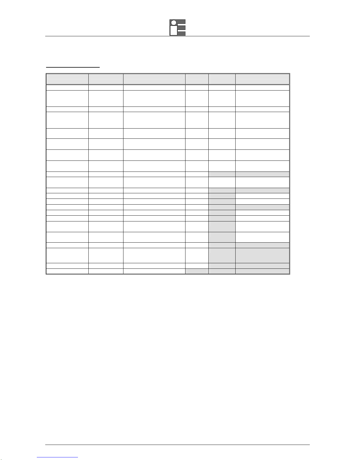
1.1.5 Flue gas probes
Probes Code Description
BB610043
90° FIXED long L=180mm+180mm Ø8mm TcK
BB610046
FIXED hose length 3mt L=300mm Ø8mm TcK
BB610047
FIXED hose length 2,5mt L=180mm Ø6mm TcK
BB610048
FIXED hose length 2,5mt L=300mm Ø6mm TcK
BB610051
FIXED hose length 3mt L=180mm Ø8mm TcK
BB610080
FIXED hose length 3mt L=750mm Ø8mm TcK
BB610081
FIXED INCONEL hose length 3mt L=750mm Ø8mm TcK
BB610112
FIXED 90° hose length 2,5mt L=300mm+450mm Ø8mm TcK
BB610119
FIXED hose length 3mt L=500mm Ø8mm TcK
BB610122
FIXED 90° hose length 2,5mt L=200mm+300mm Ø8mm TcK
1.2 Specifications
Type: 2, 3 or 4 cells hand-held flue gas analyser/Boiler tuning unit.
Calibration: automatic 60 secs. calibration procedure at instrument switching-on. Optional autozero electrovalve for
quick start-up
Self-diagnosis: Sensors efficiency test with anomalous status announcement.
Fuel types: Up to 10 totally programmable.
Pump: rate of flow 0.8 lit / head –230mbar
All data measured using 3 meters long probe and line filter connected. Load loss = 10 mbar using a 3 meters probe
extension
Power supply: High capacity Li-ion rechargeable battery pack / external battery charger.
Charging time : 3h at 90% with instrument off.
Battery life: 10h continuous operation (without printer and back-light).
Printer: Impact type 24 columns with 58 mm large and 18 meters long paper roll
Printer power supply: using the analyser battery pack.
Automatic CO(ppm) dilution: Automatic sensor protection from high CO concentration.
Internal data memory: up to 250 complete analysis data structured by Tags.
Service and user data: 3 programmable lines for each programmed customer using a PC and DBGas Software.
Report Header: 4 rows x 16 characters programmable from keyboard
Display: Large (40x56 mm) graphic LCD display with automatic back-light device. Bargraph and trend capability as
option.
Serial interface: USB standard interface.
Smoke measurement: Using the optional external manual pump. Bacharach index memory store and printout
capability as standard.
Optional probes: ambient CO, explosive gas leakage sniffer.
Working temperature: from –5°C to +45 °C (up to 50°C for short time)
Storage temperature: from –20 to +50°C (3 months maximum at temperatures exceeding the operational limits).
Dimensions: 115x90x330 mm
Weight: Nett. 1.1 kg battery and printer included
External Probes
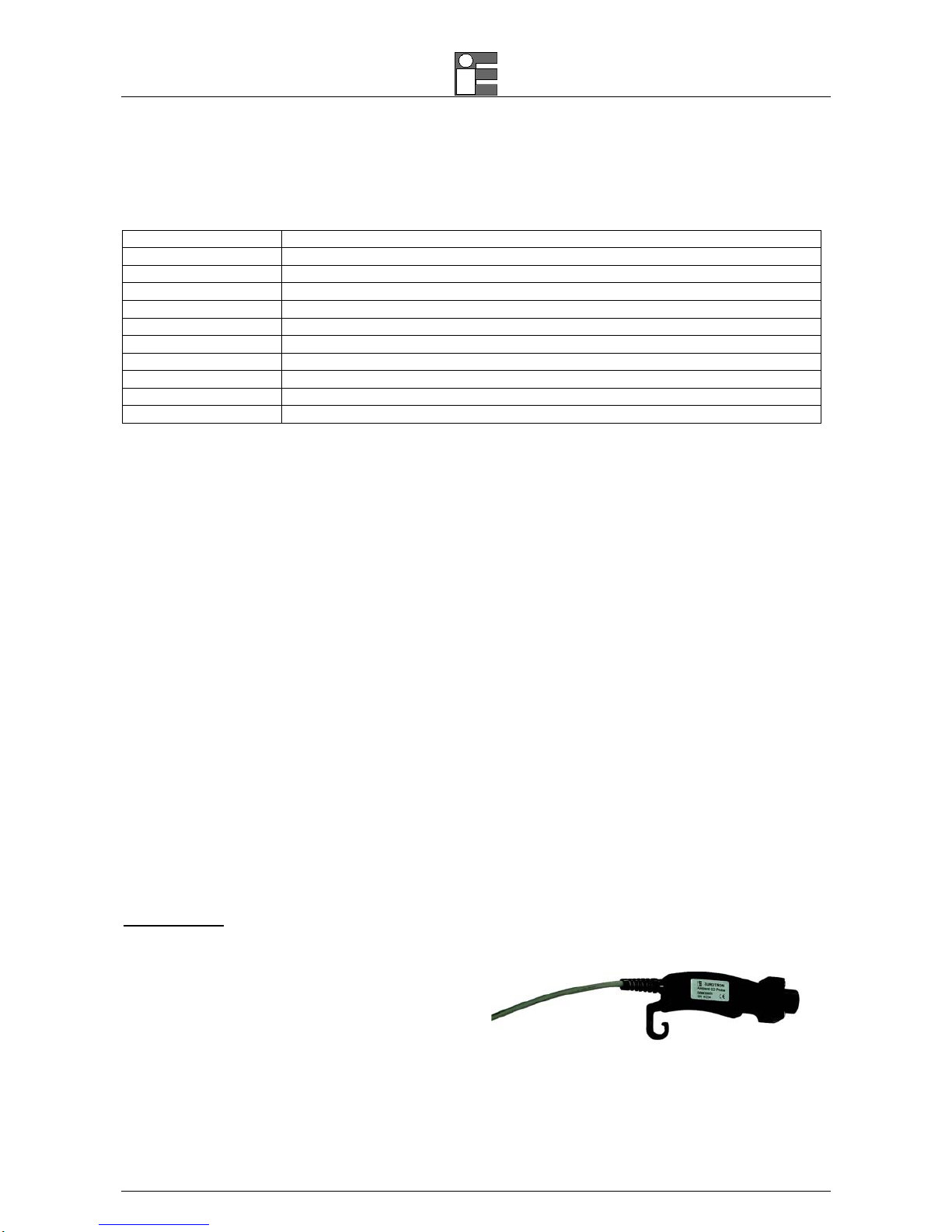
Ambient CO probe
Range: from 0 to 500ppm
Accuracy: ±5ppm up to 100ppm; ±5% up to 500ppm
Resolution: 1ppm
Response time: 30s (t90)
Waiting starting time: 30s
Working temperature: from –5°C to +45 °C

Instruction Manual MM850402 ed. 08b
13
Natural gas leak detection probe
Pre-heating time: 30s minimum
Alarms indication: visual with 5 steps
5 alarms levels: 100, 200, 300, 400, 500 ppm
Acoustic Alarm indication: respectively 1, 2, 3, 5 bip/s,
continuous
Response time: 5s (t90)
Alarm levels Accuracy: ±10% at 90 days
Low Draft Probe
• Range: ±200Pa
• Resolution: 0.1Pa
• Operative temperature range: from +5 to +45 °C
• Accuracy
From +10 Pa to -10 Pa: ±0.5 Pa
Elsewere: ±3 Pa
Instruction Manual MM850402 ed. 08b
14
Accuracies and ranges
Parameter Sensor type Range Resol. Max
responce
Accuracy
O2 Electrochemical from 0 to 25.0% 0.1% 20 sec.
±0.1% vol.
CO
H
2
compensated
Electrochemical
from 0 to 8000 ppm
1 ppm 50 sec.
±10 ppm <300 ppm
±4% rdg up to 2000 ppm
±10% rdg elsewere
CO diluted Electrochemical from 0,8 to 10% 0.05 %
CO
Electrochemical from 0 to 20.000 ppm
1 ppm 40 sec.
±10 ppm <300 ppm
±4% rdg up to 2000 ppm
±10% rdg elsewere
CO% Electrochemical from 0 to 10.00 % 0.01% 50 sec. ±0.01% up to 0.2%
±4% rdg elsewere
NO Electrochemical from 0 to 4000 ppm 1 ppm 40 sec.
±5 ppm <125 ppm
±4% rdg elsewere
NO LOW Electrochemical from 0 to 500 ppm 0.1 ppm 40 sec.
±2 ppm <40 ppm
±5% rdg elsewere
NO2 Electrochemical from 0 to 1000 ppm 1 ppm 50 sec.
±5 ppm <125 ppm
±4% rdg elsewere
NOx Calculated from 0 to 5000 ppm 1 ppm
SO2 Electrochemical from 0 to 4000 ppm 1 ppm 40 sec.
±5 ppm <125 ppm
±4% rdg elsewere
CO2 Calculated from 0 to 99.9% 0.1 %
Tair Pt100 from -10 to 100 °C 0.1 °C
±(0.2% rdg+0.15°C)
Tgas Tc K from 0 to 1000 °C 0.1 °C
±(0.3% rdg+0.3°C)
∆T
Calculated from 0 to 1000 °C 0.1 °C
Tflow Tc K from -10 to 100 °C 0.1 °C
±(0.3%rdg+0.3°C)
Treturn Tc K from -10 to 100 °C 0.1 °C
±(0.3% rdg+0.3°C)
Pressure
∆P
Piezo 0-200 hPa 0.1 hPa ±0.5 Pa up to 50 Pa
±1% rdg elsewere
Draft Piezo ±40 hPa 0.01 hPa ±0.03 Pa up to 300 Pa
±1% rdg elsewere
Excess air Calculated from 1.00 to infinity 0.01
Efficiency Calculated from 0 to 99.9%
(also for condensating boilers
with automatic detection)
0.1 %
Gas speed Pitot tube From 0 to 100.0 m/s 0.1 m/s
Smoke index External pump from 0 to 9
Technical units and ranges can be converted directly from ppm to mg/Nm3 , mg/kwh and from hPa to mmH2O, mbar or inH2O.
The relative accuracy shown are expressed as absolute or % of rdg errors at -5°C to +40°C ambient temperature.
The maximum response time shown is referred to 90% signal changes.
The pressure relative accuracy shown is valid only after the auto-zero procedure.
N.B.: Specifications may change without notice.

Instruction Manual MM850402 ed. 08b
15
2 GENERAL
2.1 Keypad & Display
The easy to use keyboard allows the operator to enter the main operative mode and all other complementary or auxiliary
modes following the menu driven instructions.
The high contrast graphic LCD (40x56 mm), equipped with an automatic back-light device, displays the measured and/or
calculated parameters in the preferred format (Zoom function). The above parameters can be also displayed in a graphic
mode.
2.2 Built-In printer
The 3000-4000 series can be equipped with a built-in, rugged, impact type printer. It uses a low cost common roll nonthermal of paper (58 mm large, 18 meters long) , more readable, long life time and heat resistant better than the thermal
printout on chemical paper. One key instruction is enough to obtain one, two or more copies of the analysis report with
header and company reference data.
2.3 Gas Sampling Probe
Flue gas sampling probes with different lengths, shapes and max. operating are available to match the requirement of
different applications. The sampling probe is connected to the instrument with a rubber hose through a combined module
of water trap and suspended particle filter.
2.4 Measuring Sensors
The 3000-4000 series use long life sensors for O
2
, CO (H2 compensated), NO, NO2 and SO2.
An automatic internal device diluted the CO concentration when a high level of CO is identified by the instrument. Dilution
system allows to extend the measuring range of the CO sensor up to 10%.
The optional Autozero valve for quick start-up allows the operator to switch the instrument with the gas probe in the
stack.
Four acoustic and visual alarms can be set on four programmable parameters.
2.5 Temperature probes
A thermocouple type K is incorporated in the tip of the gas sampling probe to measure the flue gas temperature. This
thermocouple is suitable for measurements up to 800°C (max 1000°C for few seconds). Temperature measurement and
gas sampling from the flue gas pipe are thus always performed in the same site.
The probe is connected to the instrument with the appropriate compensated cable and connector. A Pt100 resistance
thermometer (local jig or remote sensor) is used for the air temperature measurement and best efficiency calculation.
2.6 Pressure sensor
The instrument is equipped with an internal sensor for pressure and stack Draft. Easy to change to and from pressure
analysis and stack Draft. Easy to change to and from pressure analysis with a single-key operation.
As an additional standard feature , the instrument is equipped with a differential pressure sensor.
2.7 Fuel Technical Data
The instrument includes as standard the technical data for 4 of the most common fuels.
Using the optional GasConfig software, it is possible to modify or add data of up to 10 different fuels.

Instruction Manual MM850402 ed. 08b
16
2.8 Smoke Measurement
Smoke index measurement is done by using an external hand pump (supplied as an accessory), the results can be
stored in memory and printed in the report.
2.9 Remote Temperature Probe
A remote Pt100 probe is available for combustion air temperature measurement from –10°C to 100°C. This probe is
strongly recommended mainly in forced air boiler to obtain an accurate calculation of the efficiency.
2.10 Ambient CO Probe
Optional probe to monitor CO concentration and therefore safety condition in the boiler room. The instrument gives
acoustic and visual alarms if the set limit (according to the OSHA recommendation) are exceeded.
2.11 Natural Gas Probe
Optional internal or external probe to monitor CH4 and natural gas concentration and detect and locate the position of a
gas leak into the domestic pipe network.
2.12 Leak test procedure
To check gas network tightness using a pressure decay method with programmable interval time. It uses the internal
pressure sensor and a Eurotron leakage procedure.
2.13 External Low Pressure Sensor (UniGas 3000+)
The UniGas 3000+ only can use the external Pa sensor for pressure and Draft (BB830025). The sensor is a unique
vacuum meter with higher precision (± 0,5 Pa) and resolution (0,1 Pa) specification if compared to the internal sensor
ones. This sensor is useful to measurements that respond to the UNI10845.
2.14 Burner Pressure Probe
A 1 meter, 8x4mm silicon hose (cat. EE300088) is used to check the pressure inside the burner when you are installing
the heating system.
2.15 Ionization Current Probe (option)
This special probe allows the operator to measure the ionization current of the boiler and to verify the value in
accordance with the boiler specifications.
2.16 Internal Gas Sniffer Probe (option for UniGas 3000+/BTU 3000+)
An optional feature monitors the CH4 and natural gas concentration and detects and locates the position of a gas leak in
a domestic pipe network by using an internal gas sniffer sensor.
2.17 Pitot tube
The 3000-4000 series analyzer can be connected to a pitot tube for gas speed measurements.

Instruction Manual MM850402 ed. 08b
17
2.18 Calibration Certificate
Each 3000-4000 series portable gas analyzer, is factory calibrated and certified against Eurotron Standards, that are
periodically certified by an International recognized Laboratory, and shipped with a Certificate of Calibration stating the
nominal and actual values and the deviation errors.
2.19 Electromagnetic Compatibility
The instrument case, made in shock-resistant injection moulded ABS + polycarbonate has been designed to fulfill the
directive 89/336/CEE Electromagnetic Compatibility. See Appendix A1 for EMC declaration of conformity.
Instruction Manual MM850402 ed. 08b
18
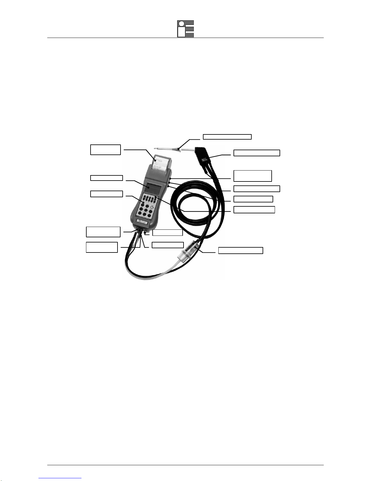
3 PHYSICAL DESCRIPTION
The 3000- 4000 series portable analyzer consists of a rugged and compact case, a mother board with all base function
circuits, 2, 3 or 4 electrochemical cells, a gas pump, a keyboard, an LCD backlighted display, a Li-Ion rechargeable
battery pack and, optionally an impact printer.
The 2 pieces of the case are jointed by 8 screws. The batteries, the pneumatic circuit and the cells are positioned in the
rear of the analyzer and 2 screws locked the lid.
A pressure lid allows the removal of the paper roll.
Positioning cone
Flue gas probe
Water trap + Line filter
Impact printer
(opt.)
Graphic Display
Keyboard
Tgas Input
P2 - ∆P Input
P1 – Draft/Pressure
input
INLET – Flue Gas
input
Battery charger
External probe and
Pt100 Tair probe input
Back-light sensor
USB port
At the bottom of 3000-4000 series you can see all sampling probe connectors: gas inlet, pressure and Draft input,
thermocouple input for gas measurement and the 2
nd
pressure inlet connector.
On the right side are the connectors for: the USB serial port, the line power charger and the auxiliary probes (T+RH%,
leak checker, etc.).
The operator interface is on the front of the instrument and it consists of: a high contrast LCD display and a 14 button
keypad. An automatic back-light device and a “zoom” function, make the data on the display much easier to read. The
most used operation (analysis, Draft, printing and smoke index) can be accessed by the operator pressing a single key.
Instruction Manual MM850402 ed. 08b
19
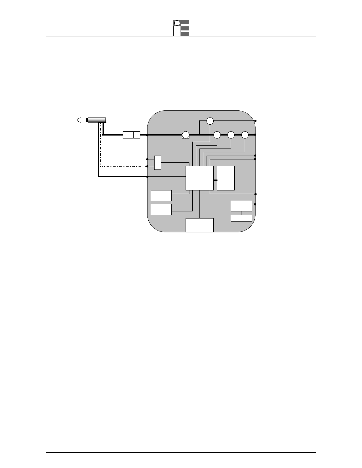
4 PRINCIPLE OF OPERATION
The 3000-4000 series analyzer is based on the following functional blocks:
MicroC ontroller
Impact printer
Keyboard
Display
250
memory
Power supply
Ni-MH battery
Battery char ger input
External probe input
Pt100 Tair input
Gas outlet
P2 - ∆P
P1 – Draft/Press ure
Differential
pressure
sensor
Gas input
INLE T
Pump 1° Sensoe O2
3° Sensor
TcK Tgas input
Water trap
Line filter
RS232
2° Sensor CO
4° Sensor
4.1 Measurement Principle
The gas is sampled and aspirated through the probe with a primary pump powered at constant voltage.
To position the sampling probe in the exhaust gas pathway a hole of 11mm, up to 16mm, should be drilled and the
retaining cone of the sampling probe firmly screwed in it.
The retaining screw in the cone enables the probe to be easily moved to locate the core flow, normally correspondent to
the center of the section of the smoke tube. The flue gas and exhaust gas pathway, should be checked for gas-tightness
before carrying out a measurement and, if necessary, non gas-tight points should be sealed.
The O2 sensor is essentially an electrochemical cell, with two electrodes and electrolyte solution. The behavior is similar
to a normal battery and therefore the sensitivity decreases with time. The expected life does not relate to the operative
time and is lost after approximately 24 months.
The toxic gas measurements (CO, SO
2
, NO and NO2) use electrochemical cells, with an expected operative life of 3
years.
The electrochemical cell grants accurate results for time intervals of approximately 60 minutes. The zero drift is
automatically corrected by the instrument every time the instrument is switched-on, using fresh ambient air as reference.
This operation should be made with the sampling probe not inserted in the chimney or with the sampling probe
pneumatic connector disconnected from the analyser gas inlet.
When a long analysis has to be made, a new autozero procedure should be performed.
The pressure/Draft sensor is based on the principle of the extension metric measuring bridge. When the instrument is
switched-on, a zero calibration of the Draft/pressure circuit is also executed. Leave open the “∆P” connector during this
phase.
Measured and calculated parameters are indicated on a LCD alphanumeric display (40x56 mm), equipped with a
automatic back light device for easy readings, mainly in poorly lit conditions.
4.1.1 Gas Sampling Probe
The sampling probe consists of a steel tube and a handle of thermo-insulated material. A positioning cone allows user to
place the probe in holes with a diameter from 11 to 16 mm.
The gas temperature is acquired using a thermocouple type K with the junction placed in the tip of the probe.
Instruction Manual MM850402 ed. 08b
20
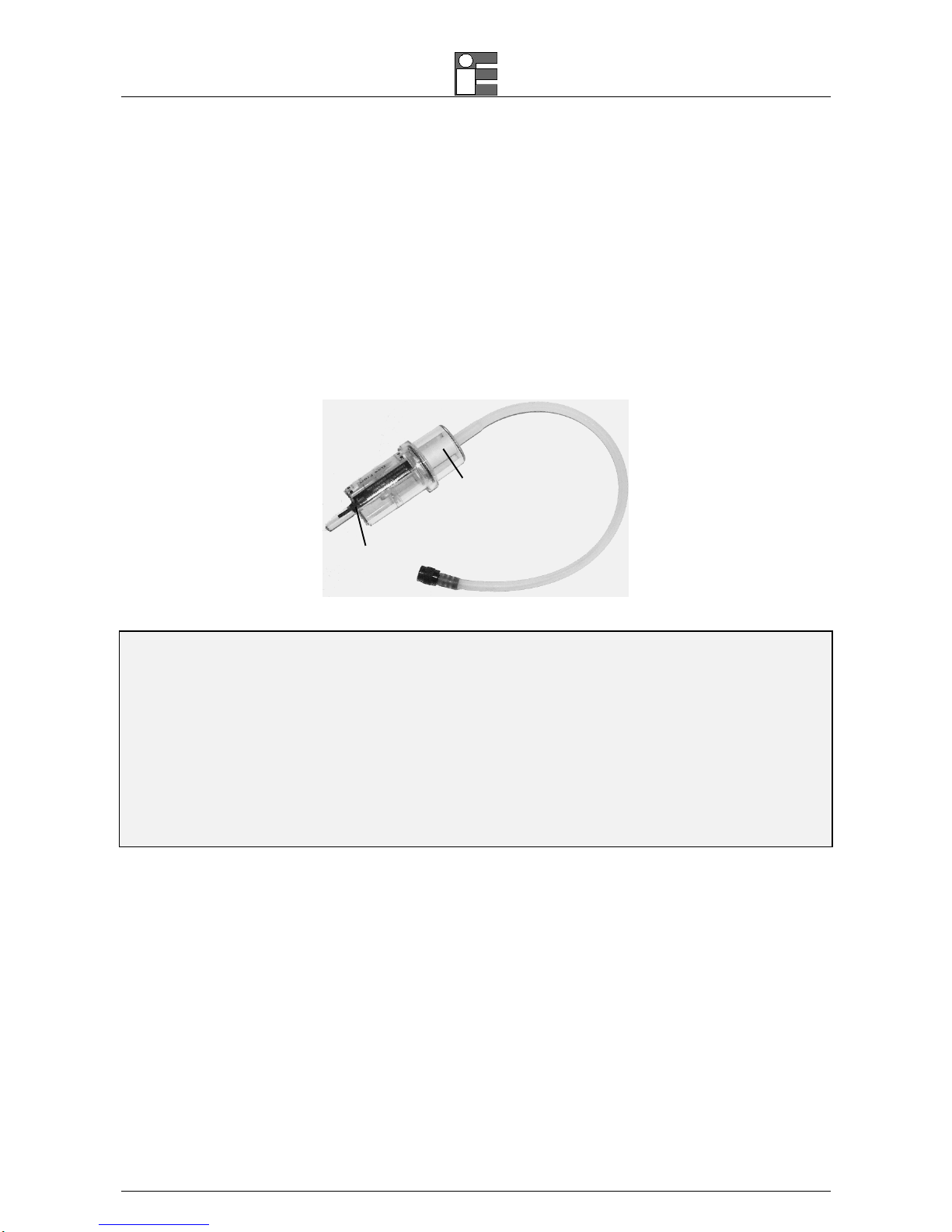
4.1.2 Water Trap & Line Filter
The gas flows through an external combined water trap and line filter to avoid the presence of condensation and
suspended solid particles in the analysis section of the instrument. A cylinder is positioned at 15 cm from the instrument
gas inlet it is divided into two parts: the water trap and the line filter.
The water trap works using the expansion principle: the gas flow decreases its speed inside the cylinder and it will cool;
the humidity will condense and the solid particles fall down. The section of the water trap must be periodically drained off
to avoid water from entering the analysis section. Pull the rubber plug (cat. EE650081) and shake slowly the trap to drain
any condensation. Push the rubber plug to close the trap hole.
The line filter is positioned after the water trap and before the electrochemical cell. Its function is to stop the smallest
solid particles before the analysis. Remember to change the filter (cat. EE650074) every time it is dirty.
Line filter
cat. EE65007 4
Rubber plug
cat. EE650081
WARNING
THE WATER TRAP MUST BE KEPT IN A VERTICAL POSITION DURING GAS SAMPLING. AN INCORRECT POSITIONING OF THE TRAP CAN
ALLOW THE WATER TO ENTER INSIDE THE ANALYZER AND DAMAGE THE ELECTROCHEMICAL SENSORS.
NEVER MAKE ANY ANALYSIS WITHOUT THE DRAINING RUBBER PLUG. THE MEASUREMENTS WILL BE INCORRECT.
WHEN YOU FINISH THE ANALYSIS, REMEMBER TO DRAIN THE WATER TRAP. BEFORE PUTING THE GAS PROBE IN THE CARRYING CASE,
REMOVE THE CONDENSATION WATER FROM THE PROBE HOSE.
TO OPEN THE WATER TRAP GENTLY ROTATE THE TWO PARTS: DON'T FORCE THEM
THE LINE FILTER SHOULD BE REPLACED WHEN DIRTY. NEVER MAKE ANY ANALYSIS WITHOUT LINE FILTER AND/OR WATER TRAP, AS IT
CAUSES AN IRREVERSIBLE DAMAGE TO THE ELECTROCHEMICAL SENSOR.
4.1.3 Gas Sensors
The analyzer uses long life sensors for O2, CO (H2 compensated), NO, NO2 and SO2. The sensor do not need special
maintenance but must be replaced after the expected lifetime.
However a full maintenance and certification of the instrument is recommended once a year.
The gas sensors are electrochemical cells composed by two electrodes (anode and cathode) and an electrolyte solution.
The sampled gas goes through a selective diffusion membrane.
The oxidation process produces an output electrical signal proportional to the gas concentration. The signal is evaluated
by the electronics, converted to digital, processed by the microprocessor, displayed and printed with a 0.1% volume
resolution.
The flue gas must not be at a pressure that could damage or destroy the sensor. Measurements are always carried out
under "pressureless" conditions. The maximum permissible excess/reduced pressure is ±100 mbar.
Each sensor has a different response time:
O
2
=
20s to 90% of reading
CO (H
2
comp.) = 50s to 90% of reading
CO = 50s to 90% of reading

Instruction Manual MM850402 ed. 08b
21
NO = 40s to 90% of reading
NO
2
=
50s to 90% of reading
SO
2
= 40s to 90% of reading
N
OTE: TO OBTAIN AN ACCURATE MEASURE IT IS RECOMMENDED TO WAIT 3-5 MINUTES.
Toxic gas sensor can be present a ±2% drift and a long resuming time it an excessive (>150% of F.S.) gas concentration
is applied. In that case it is recommended to wait for a measured value lower than 20ppm, by sucking fresh air before
turning off the analyzer.
An optional Electro-valve can be installed inside the instrument to exclude/include manually or automatically the CO cell
when the CO concentration is too high (e.g. when the burner is starting)
Four acoustic and visual alarm levels can be set on four programmable parameters.
4.2 Auxiliary Measurements
4.2.1 Temperature Measurements
The instrument is equipped with two temperature inputs to measure exhaust gas and the burner air input temperatures
(combustion gas).
♦ A thermocouple type K (nickel-nickel chromium) is included in the tip of the gas sampling probe to measure the flue
gas/exhaust gas temperature. This thermocouple is suitable for permanent measurements at temperatures up to
800°C and for short-term measurements up to 1000°C. Temperature measurement and gas sampling from the flue
gas pathway are thus always performed at the same site. The probe is connected to the apparatus with
compensated cable and connector. An internal Pt100 resistance thermometer is used for cold junction
compensation.
♦ The same Tc K input can be used to measure the flow and return temperature in water circuit. If you have to
measure the water temperature measuring the pipe temperature, use an arch-model thermocouple with an
appropriate diameter.
♦ A remote Pt100 sensor, can be supplied on request with a 2 or 5 meter cable to measure the air inlet temperature
in
forced air boiler. This option is very important for an accurate efficiency calculation.
4.2.2 Pressure and Draft
The analyzer can be equipped with a temperature compensated pressure sensor to measure the chimney Draft or
pressure. The pressure range is from -40 hPa to + 200.0 hPa.
The sensor is factory calibrated and does not require manual adjustment.
The zero drift, caused by ambient air temperature variation, is automatically cancelled at each instrument start-up. In
addition, for more accurate readings the operator can reset, using the pertinent key, the zero if required. The instrument
sensor is differential type and, if connected to a Pitot tube, it can be used to measure gas speed.
N
OTE: FOR A MORE ACCURATE READINGS WE SUGGEST TO EXECUTE THE AUTOZERO PROCEDURE BEFORE PERFORMING THE
MEASUREMENT
.
CAUTION
IF A SINGLE TUBE GAS SAMPLING PROBE IS USED FOR PRESSURE/DRAFT MEASUREMENTS, BE SURE THAT IT IS CLEAN AND DRY
BEFORE CONNECTION TO THE PRESSURE INPUT.
CAUTION
A +300HPA (OR –300HPA) OVER-PRESSURE CAN PERMANENTLY DAMAGE THE PRESSURE SENSOR.
Instruction Manual MM850402 ed. 08b
22
4.2.3 Smoke Index Measurement (option)
This method consists of taking a gas sample from the center of the gas pipe behind the heat exchanger and crossing it
through a special filter paper.
The color of the spot on the filter is compared with a graduated (from 0 to 9) reference scale and it is called “smoke
index”.
You can type in the instrument up to 3 smoke index values; the analyzer calculates the average value and can print
these values on the report.
Normative and laws about the air pollution, describe the procedure: DIN51402, 2116, 2117 and 2297 VDI directives,
ASTM D 2156-63 T, etc.
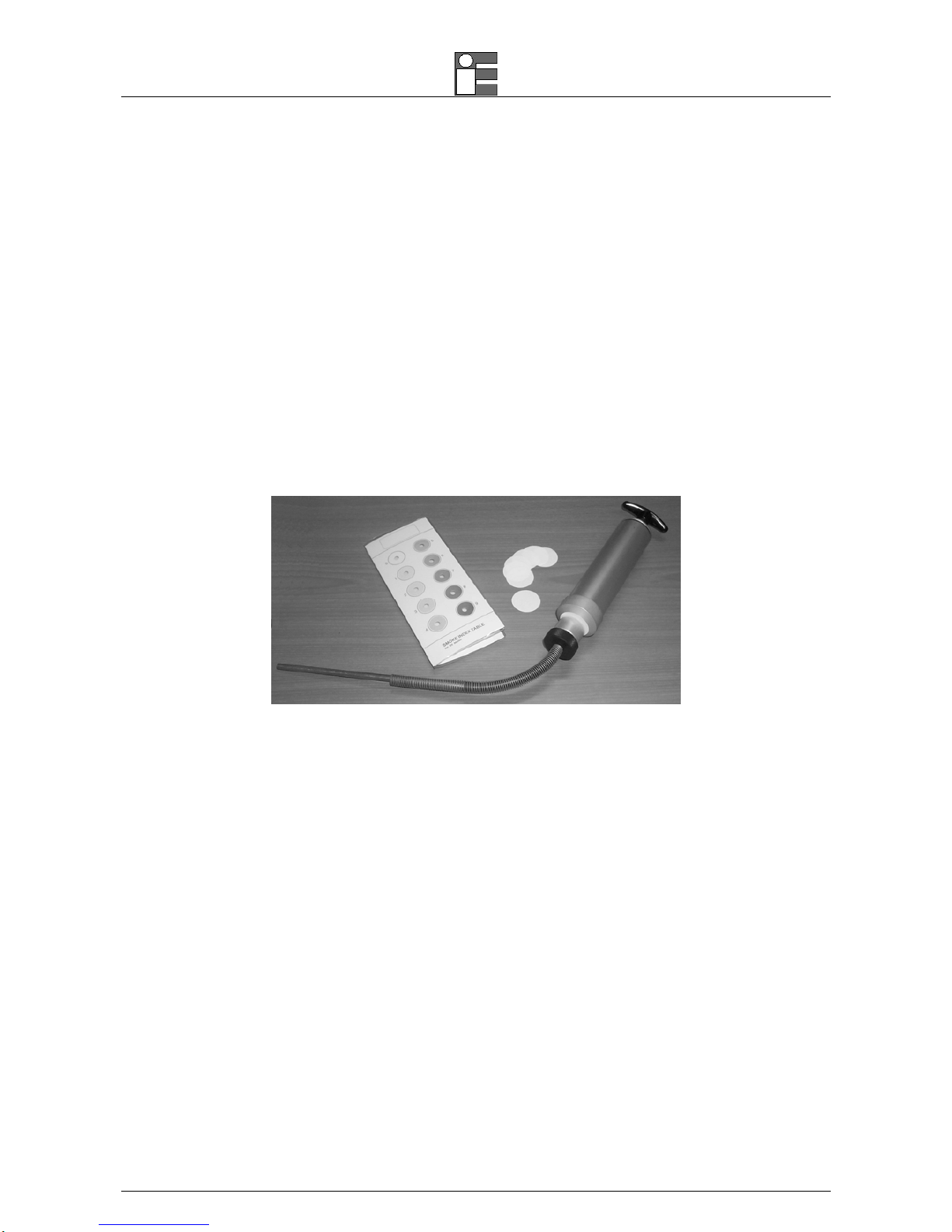
4.2.3.1 Measuring Instruments (option)
1. Smoke pump: it should suck 5.75 litres ±0.25 l (normalized to 0°C, 760mmHg) through a 1 cm
2
filter.
2. Smoke index reference table: it is a grey scale sheet with 10 different areas numbered from 0 to 9. The number 0
corresponds to a 85% ±2.5% reflection. Every area reflects 10% less than the previous one. The scale is used to
compare the scale with the paper filter and to calculate the smoke index.
3. Paper filter: When it is clean it has a reflection corresponding to the 0 scale index. It also has 3 litres per cm
2
a
minute (normalized to 0°C, 760mmHg) with a 200/800 mmwc resistance to the air flux.
 Loading...