

Eurotron IRtec Rayomatic 14 MK2 Instruction Manual

IRtec Rayomatic 14 MK2
Process IR temperature transmitters
Instruction Manual MM850618 ed. 01e

Instruction manual MM850618 ed. 01e
INTRODUCTORY NOTE
ATTENTION: THIS MANUAL IS VALID FOR IRTEC RAYOMATIC 14 MK2.
This publication contains operating instructions, as well as a description of the principles of
operation, of IRtec
This information covers all models of the instrument, including the basic equipment and its options
and accessories. This manual is a complete “USER GUIDE”, providing step-by-step instructions to
operate the instrument in each of its designed functions.
Eurotron has used the best care and efforts in preparing this book and believes the information in
this publication are accurate. The Eurotron products are subjected to continuous improvement, in
order to pursue the technological leadership; these improvements could require changes to the
information of this book.
Eurotron reserves the right to change such information without notice.
No part of this document may be stored in a retrieval system, or transmitted in any form, electronic
or mechanical, without prior written permission of Eurotron.
IRtec IR thermometers uses sophisticated analog and digital technologies. All maintenance
operation must be carried out by qualified personnel
engineers for any support requirements.
IRtec is fully tested in conformity with the directive n°89/336/CEE Electromagnetic Compatibility
and therefore had the CE mark. Eurotron shall not be liable in any event, technical and publishing
error or omissions, for any incidental and consequential damages, in connection with, or arising out
of the use of this book.
®
Rayomatic 14 MK2 IR thermometers.
ONLY. We recommend contacting our
IRtec® is a registered trademark of Eurotron Instruments S.p.A.

Instruction manual MM850618 ed. 01e
TABLE OF CONTENTS
1 GENERAL DESCRIPTION................................................................................................... 5
1.1 Specifications.................................................................................................................................. 6
1.2 Optical Charts ................................................................................................................................. 6
1.3 Optic heads diagrams ..................................................................................................................... 7
1.3.1 CloseFocus-Optics.......................................................................................................................... 8
1.4 Ordering code ................................................................................................................................. 8
1.4.1 Accessories .................................................................................................................................... 9
2 PHYSICAL DESCRIPTION................................................................................................. 10
3 PRINCIPLE OF OPERATION............................................................................................. 11
4 UNPACKING.......................................................................................................................12
5 INSTALLATION.................................................................................................................. 13
5.1 Electrical installation ..................................................................................................................... 13
5.1.1 Cable Connections........................................................................................................................ 13
5.1.2 Outputs ......................................................................................................................................... 15
5.2 Functional Inputs........................................................................................................................... 15
5.3 Mechanical installation.................................................................................................................. 15
6 OPERATIONS..................................................................................................................... 19
6.1 Programming Flow Chart .............................................................................................................. 19
6.1.1 A: Parameter settings for head changing...................................................................................... 21
6.1.2 B: Laser settings ........................................................................................................................... 22
6.1.3. C: Password setting...................................................................................................................... 22
6.1.4 D: Alarms settings......................................................................................................................... 23
6.1.5 E: Display settings ........................................................................................................................ 24
6.1.6 F: Set settings............................................................................................................................... 25
6.1.6.1 Fa: X HD SET submenu........................................................................................................... 26
6.1.7 G: Diagnostic ................................................................................................................................ 26
6.2 Data logging card.......................................................................................................................... 28
6.2.1 Blocks configuration...................................................................................................................... 28
6.2.1.1 Time tracking mode.................................................................................................................. 28
6.2.1.2 Edge mode............................................................................................................................... 29
6.2.1.3 System mode ........................................................................................................................... 29
6.2.2 Log sub-menu............................................................................................................................... 29
6.2.2.1 Cleaning one block memory..................................................................................................... 31
7 SIGNAL PROCESSING...................................................................................................... 32
7.1 Signal Processing ......................................................................................................................... 32
7.2 Signal Post Processing ................................................................................................................. 33
7.3 Output Signals .............................................................................................................................. 34
7.4 Advanced Settings ........................................................................................................................ 36
8 DIGITAL INTERFACES...................................................................................................... 37
8.1 Connecting a card......................................................................................................................... 38
8.2 Connecting to a PC....................................................................................................................... 41
8.2.1 USB installation............................................................................................................................. 41
8.2.1.1 Installing the USB driver........................................................................................................... 41
8.2.1.2 Checking the installed COM port.............................................................................................. 43
9 IRSETUP SOFTWARE....................................................................................................... 48
System requirements .................................................................................................................................. 48
Installing the Software................................................................................................................................. 48
9.3 Uninstalling the Software .............................................................................................................. 48
9.4 Instrument configuration ............................................................................................................... 48
9.5 Temperature monitor .................................................................................................................... 49
9.6 GRAPHIC MODULE ..................................................................................................................... 51
10 MAINTENANCE.................................................................................................................. 53
10.1 Purge Air Supply........................................................................................................................... 53
10.2 Optical system cleaning ................................................................................................................ 53
10.3 Mounting Device ........................................................................................................................... 53
10.4 Interconnection Cable ................................................................................................................... 53
10.5 Storage ......................................................................................................................................... 53
3

Instruction manual MM850618 ed. 01e
11 CERTIFICATES ..................................................................................................................54
11.1 Warranty Terms............................................................................................................................. 54
11.2 Letter of Conformity .......................................................................................................................54
11.3 EMC Conformity ............................................................................................................................54
11.4 Disposal......................................................................................................................................... 54
APPENDIX ....................................................................................................................................... 55
A1 Visual Alarms .....................................................................................................................................56
A2 How to determine an object emissivity...............................................................................................57
A2.1 Typical Emissivity Values ..............................................................................................................57
A2.2 Metals - Typical Emissivity Values.................................................................................................58
A2.3 Non-Metals - Typical Emissivity Values........................................................................................60
4

Instruction manual MM850618 ed. 01e
1 GENERAL DESCRIPTION
Infrared thermometers measure the object surface temperature without touching it. They calculate the surface
temperature on the basis of the emitted infrared radiation from an object. The most important feature of
infrared thermometers is that they enable the user to measure objects contact less. Consequently, these
products help to measure the temperature of inaccessible or moving objects without difficulties.
As the infrared sensor Eurotron IRtec Rayomatic 14 consists of two pieces (miniature sensing head with
separate electronics) it can easily be installed in a variety of applications, especially if industrial environment
requires space-saving installation. The stainless steel sensing head as well as the teflon-coated cable are
standard equipment for ambient temperatures up to 180 °C. The labeling of each sensing head with the
according calibrating code allows the exchange of head or electronic box without additional calibration.
The sensor electronics of the IRtec Rayomatic 14 is placed inside a rugged die casting box. Various analogue
outputs (0/4 – 20 mA, 0 – 10 V, thermocouple type J or K) and optional digital interfaces (USB, RS232,
RS485) are available.
Easy accessible programming keys and a back-lit LCD display permit a Smart Panel-Operation to set
and adjust essential parameters on-site.
Report of Calibration
IRtec Rayomatic is delivered, on request, with a Report of Calibration, traceable to the International Standards
stating the nominal and actual values and the deviation errors.
RS232 & Software
An optional RS232 PC adapter allows the changes of the configuration parameters (emissivity, response time,
measuring span, average, peak-picker, decay, etc) and digital communication for remote PC display of
temperature. The software LogMan let the operator to monitor the temperatures in real time mode with a
graphic visualization too. The measured values can be stored and afterward re-managed on the PC for your
future needs.
5

Instruction manual MM850618 ed. 01e
1.1 Specifications
Spectral range: 8 to 14 µm
Response time: 150 ms (95 %) - HS: 12ms (90%), 8 ms (63%)
Accuracy: ±1 % or ±1 °C whichever is greater (T> -20 °C; ambient temperature +23 °C ±5 °C)
Repeatability: ±0,5 % or ±0,5 °C whichever is greater
Temperature Coefficient: ±0,05 %/ K or ±0,05 K/ K whichever is greater
Signal processing: peak hold, valley hold, average
Emissivity: 0.100 to 1.100 (manual or digital adjustable)
Transmission: 0.100 to 1.100 (manual or digital adjustable)
Power supply: 8 VDC to 36 VDC
Current draw: max. 100 mA
Outputs/ analog:
Object temperature: 0 to 20 mA or 4 to 20 mA or 0 to 5 V or 0 to 10 V or thermocouple type J or K
Head temperature: 0 to 5 V or 0 to 10 V; 10 mV/ K or alarm output
Relais: 2 x 60 VDC/AC, 0,4 A; optically isolated (optional module)
Output impedances:
mA max. loop resistance 500 Ω (at 8 -36 VDC),
mV min. 100 KΩ load impedance
Thermocouple 20 Ω
Functional inputs F1, F2, F3; software programmable for the following functions: external emissivity
adjustment, ambient temperature compensation, trigger
Digital interface: USB, RS232, RS485 (optional modules)
Environmental rating: IP65 (NEMA-4)
Ambient temperature: Sensing heads: -20 to 180 °C (25:1 head) / -20 to 120 °C (HS 14:1 and 2:1 heads) Electronic box: 0 to 65 °C
Storage temperature: Sensing head: -40 to 180 °C (120°C for HS, 14:1 and 2:1 heads) - Electronic box: -40 to
85 °C
Vibration (sensor): IEC 68-2-6: 3G, 11-200 Hz, any axis
Shock (sensor): IEC 68-2-27: 50 G, 11 ms, any axis
Relative humidity: 10 to 95 %, non condensing
Dimensions: Sensing head: Ø28 mm x 14 mm (M12x1) - Electronic box: 89 mm x 70 mm x 30 mm
Weights: Sensing head: 40 g - Electronic box: 450 g
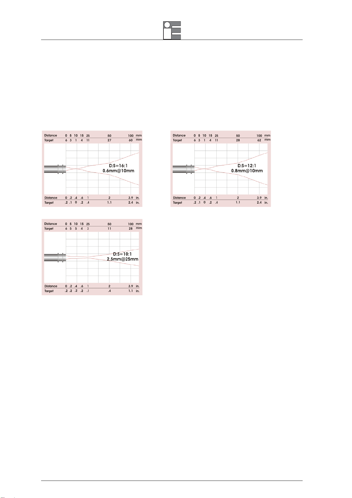
1.2 Optical Charts
The following optical charts show the diameter of the measuring spot in dependence on the distance between
measuring object and sensing head. The spot size refers to 90 % of the radiation energy.
6

Instruction manual MM850618 ed. 01e
1.3 Optic heads diagrams
25:1 Miniaturized Head
25:1 Compact head with built-in “True Target Size" TTS dual laser pointer
95:1 Advanced optics head with built-in TTS
7
Instruction manual MM850618 ed. 01e
1.3.1 CloseFocus-Optics
The optional CF-lens allows the measurement of small objects. The minimum spot size depends on the used
sensing head:
0.6 mm@ 10 mm with 25:1-head
0.8 mm@ 10 mm with 14:1-head
2.5 mm@ 25 mm with 2:1-head
The following optical charts show the diameter of the measuring spot in dependence on the distance between
measuring object and sensing head. The spot size refers to 90 % of the radiation energy.
1.4 Ordering code
Cat. 1158 - A - B - C - D
Table A Optics / Ranges
814-2 2:1 / -40 to 600°C
814-14 14:1 / -40 to 900°C
814-25 25:1 / -40 to 1000°C
814-25LS1 25:1TTS Dual Laser Pointer / -40 to 1000°C
814-25HS 25:1 HS (8 ms) / -40 to 600°C
814-25LSHS 25:1 LS HS (8 ms) / -40 to 600°C
814-95LSHS 95:1 LS HS (8 ms) / -40 to 600°C
814-95LS1 95:1TTS Dual Laser Pointer / -40 to 1000°C
814-95LSCF Close Focus / -40°C to 1000°C
814-SP Special on request
Table B Head Cable length
1m 1 mt
2m 3 mt
8m 8 mt
15m 15 mt
Xm Special length on request
8
Instruction manual MM850618 ed. 01e
Table C Options
NN None
RS232 RS232 interface + IRSetup software
RS485 RS485 interface + IRSetup software
USB USB interface + IRSetup software
PROFI Profibus
RELAY Relais interface (2x optically isolated)
LOG vent/Data Logging
Table D Report of Calibration
NO None
EC Eurotron NIST or EA traceable with data
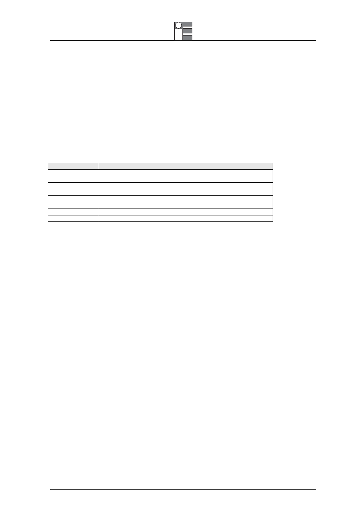
1.4.1 Accessories
Ordering Code Description
EE290148 Standard Air Purge
EE290151 Laminar flow Air purge (for severe applications)
EE290147 90° square mounting bracket
EE290149 2 axis mounting bracket
EE290150 3 axis mounting bracket
EE280495 M12x1 Mounting nut
EE360124 Close Focus lens
BB260196 Rayomatic 14 LogMan software
9

Instruction manual MM850618 ed. 01e
2 PHYSICAL DESCRIPTION
IRtec Rayomatic radiation thermometers are designed to use the most advanced sensor technology.
The head external case is made of stainless steel with M12x1 thread compatible with a wide range of
accessory.
The case is equipped with a single lens optic system, optic filter, sensor, and electronics for signal
conditioning. The instrument is IP65 protected.
10

Instruction manual MM850618 ed. 01e
3 PRINCIPLE OF OPERATION
Basics of Infrared Thermometry:
Depending on the temperature each object emits a certain amount of infrared radiation. A change in the
temperature of the object is accompanied by a change in the intensity of the radiation. For the measurement
of “thermal radiation” infrared thermometry uses a wave-length ranging between 1 µ and 20 µm.
The intensity of the emitted radiation depends on the material. This material contingent constant is described
with the help of the emissivity which is a known value for most materials (see enclosed table emissivity).
Infrared thermometers are optoelectronic sensors. They receive thermal radiation and transform it into
measurable electrical signals. Infrared thermometers basically consist of the following components:
lens
spectral filter
detector
electronics (amplifier/ linearization/ signal processing)
The specifications of the lens decisively determine the optical path of the infrared thermometer, which is
characterized by the ratio Distance to Spot size.
The spectral filter selects the wavelength range, which is relevant for the temperature measurement. The
detector in cooperation with the processing electronics transforms the emitted infrared radiation into electrical
signals.
Maximum Distance and Spot Size:
The size of the measuring object and the optical resolution of the infrared thermometer determine the
maximum distance between sensing head and measuring object. In order to prevent measuring errors the
object should fill out the field of view of the optics completely. Consequently, the spot should at all times have
at least the same size like the object or should be smaller than that.
Ambient Temperature:
The IRtec Rayomatic 14-high-temperature sensing heads are designed to measure temperatures while
tolerating ambient temperatures ranging between -20°C and 180 °C (25:1 head) or from -20°C to 120 °C (HS
14:1 and 2:1 heads). The cable between head and electronics is teflon coated and also usable for this ambient
temperature range. Therefore measurements in the specified range can be done without a cooling of the
sensing head.
Air Purity:
The lens must be kept clean at all times from dust, smoke, fumes and other contaminants in order to avoid
reading errors and damage to the lens. For that purpose an air purge collar is available as an accessory part.
Make sure to use oil-free, technically clean air, only.
11

Instruction manual MM850618 ed. 01e
4 UNPACKING
Remove the instrument from its packing case and remove any shipping ties, clamps or packing materials.
Carefully follow any instruction given by any attached tags.
Inspect the instrument from scratches, dents, damages to case corners etc. which may have occurred during
shipment.
If any mechanical damage is noted, report the damage to the shipping carrier and then notify Eurotron
directly or its nearest agent, and save the damaged packaging for inspection.
A label, on the instrument, shows the serial number and model of the unit.
Refer to these numbers for any inquiry for service, spare parts supply or application and technical support
requirements.
12

Instruction manual MM850618 ed. 01e
size
y
5 INSTALLATION
IRtec Rayomatic installation is quite easy. The cylindrical stainless steel case is externally threaded and
allows quick installation of all available accessories.
The following procedure should help you during the installation procedure of your IRtec Rayomatic
thermometer.
• The emissivity is standard set to 0.95 and the temperature span is set as required in the ordering table. If
you need different values, read the configuration of the thermometer by using the configuration software
and the Smart/RS232 converter. Connect the IRtec Rayomatic 14 to the PC and set the mathematical
function, the emissivity and the temperature span.
• Connect, if necessary, all accessories such as air purge, support, sighting tube, etc. Install and align the
IRtec Rayomatic to the process.
• Connect the signal cable to the receiver (controller, indicator, etc.) paying attention to the polarity.
• Aim accurately the thermometer to your target. Refers to Target vs. distance table on the relevant section
1. Be sure that your target is well inside the measuring area.
IRtec Ra
Background
omatic
Best
The target is
greater than spot
size
Good
The target is equal
to spot size
Incorrect
The target is
smaller than spot
WARNING
DO NOT INSTALLING THE THERMOMETER IN AMBIENT WITH TEMPERATURE HIGHER THAN +60°C WITHOUT AN ADEQUATE
COOLING SYSTEM.
5.1 Electrical installation
IMPORTANT NOTE
THE CABLE SHIELD MUST BE GROUNDED AT ONLY ONE POINT, WHICH IS USUALLY AT THE CONTROLLER/INDICATOR SIDE.
OTHERWISE, IT CAN BE DONE AT A JUNCTION BOX OR OTHER SUITABLE LOCATION IN THE FIELD AREA.
5.1.1 Cable Connections
For the electrical installation please open at first the cover of the IRtec Rayomatic 14 electronic box (2
screws). Below the display are the screw terminals for the cable connection.
13

Instruction manual MM850618 ed. 01e
Fig. 4-1: Open IRtec Rayomatic 14 electronic box with screw terminals
Designation:
+8 ... 36VDC Power supply
GND Ground (0V) of power supply
GND Ground (0V) of internal in- and outputs
OUT-TC Analog output thermocouple (J or K)
OUT-mV/mA Analog output object temperature (mV or mA)
AMB Analog output head temperature (mV)
F1-F3 Functional inputs
PINK Power supply laser (+)
GRAY Power supply laser (–)
BROWN Temperature probe head
WHITE Temperature probe head
GREEN Detector signal (–)
YELLOW Detector signal (+)
Power supply:
Please use a power supply unit with an output voltage of 8 – 36 VDC/ 100 mA.
Cable connection:
The cable gland M12x1,5 allows the use of cables with a diameter of 3 to 5 mm.
To prevent electrical and electromagnetic faults and variance of measuring values keep to the following
precautions:
Please install the measuring head and the electronic box in a distance as far as possible from any source,
which may cause electromagnetic interference (e.g. modules with electromotor-impulse).
If necessary, mount the head insulated to prevent ground loops.
CAUTION: Use shielded cables only. The sensor shield has to be grounded.
Preparation of the cable:
Remove the isolation from the cable (40 mm power supply, 50 mm signal outputs, 60 mm functional inputs).
Cut the shield down to approximately 5 mm and spread the strands out. Extract about 4 mm of the wire
isolation and tin the wire ends.
Installation of the cable:
Place the following components one after the other onto the prepared cable end:
The cap, the clamp ring, the rubber washer and one metal washer of the cable gland. Spread the strands and
fix the shield with the second metal washer. Insert the cable into the cable gland until the limit stop. Screw the
cap tight. Every single wire may be connected to the according screw clamps according to their colors.
Sensing head/ -head cable:
The standard delivery includes the connected cable of the sensing head to the electronic box. You may
shorten but never lengthen the cable. To shorten the cable may cause additional measuring errors of about
0,1 K/ m.
The head is exchangeable.
14

Instruction manual MM850618 ed. 01e
CAUTION: After exchanging a head the calibration code of the new head must be entered into the electronics
5.1.2 Outputs
The IRtec Rayomatic 14 has two output channels. The channel Out-mV/mA 1 is used for the object
temperature and for the alarms. The IRsetup software allows the programming of this output as an alarm
output.
NOTE:
THE ALARMS VALUES CORRESPOND THE MINIMUM AND MAXIMUM TEMPERATURE FOR THE USED CHANNEL. THEY
ARE ALSO RELATED TO THE SETTINGS
Output Range Connection-Pin on
Voltage 0 ... 5 V OUT-mV/mA
Voltage 0 ... 10 V OUT-mV/mA
Current 0 ... 20 mA OUT-mV/mA
Current 4 ... 20 mA OUT-mV/mA
Thermocouple TC J OUT-TC
Thermocouple TC K OUT-TC
Tab. 4-1: Analog outputs
NOTE:
ACCORDING TO THE CHOSEN OUTPUT SIGNAL THERE ARE DIFFERENT CONNECTI ON PINS ON THE IRTEC BOARD
(OUT-MV/MA OR OUT-TC).
Output channel 2 (connection pin OUT AMB) is used for the head temperature (0-5V or 0-10V) or as alarm
output. Activating this channel as alarm output requires the IRsetup software. Additionally to the head
temperature also the object or electronic box temperature can be selected as alarm source.
.
IRtec Rayomatic 14-Board
5.2 Functional Inputs
The three functional inputs F1 – F3 can be programmed with the IRsetup software and the optional serial
output. The F3 pin can be also activated by keyboard and it allows to select the source for the temperature
compensation of the optical head.
F1 (digital): trigger for reset of the peak-hold or valley-hold functions (lower active)
F2 (analogue): external emissivity adjustment (0 – 10 V: 0V Æ 0,1; 9 V Æ 1; 10 V Æ 1,1)
F3 (analogue): external compensation of ambient temperature (0 – 10V, corresponds to the
temperature range from -20 to 200°C and it is configurable with the IRsetup software)
F1 – F3 (digital): emissivity (digital choice via table, non-connected input represents high-level)
5.3 Mechanical installation
IRtec Rayomatic 14 heads are equipped with a metrical M12x1-thread and can be installed either directly via
the sensor thread or with the help of the hex nut (delivered as standard) to the mounting bracket available.
Various mounting brackets, which make the adjustment of the sensing head easier, can be additionally
ordered as accessories. Make sure to keep the optical path clear of any obstacles when adjusting the head to
the object.
15

Instruction manual MM850618 ed. 01e
Fig. 5-1: Dimensions IRtec Rayomatic 14 head and electronic box
In order to align the bracket with the target, look through the support hole (without the thermometer) and find
the best position. It's important for the optic path to be free from any obstruction (steam, dust, etc.). In
particular, when the surface is targeted through a hole, the hole diameter has to be big enough according to
the distance from the instrument. The thermometer has to be installed in an accessible place for any further
maintenance operation, and it hasn't to be exposed to excessive heat, smoke and steam.
SNAP-IN Fixing for Fast Mounting Tilting Panel for Easy Connection
Air Purge collars
The optical path between the lens and the target, should be as much free as possible from smoke and steam.
Use air purge collar to keep dust, fumes, moisture and other contaminants away from the lens.
16

Instruction manual MM850618 ed. 01e
M12x1
EE290148 Standard air purge
Brackets
All sensors come with a 1 m cable and a mounting nut. The sensor can be installed on using the optional
bracket or equivalent system.
50
2
R15
Ø18.5
R15±0.1
Fs3
50
R3
Ø3.2
Fs3Fs3
2
0
°
30
°
5
4
R23
°
0
2
Fs3Fs3
+0.4
+0.2
3
4
5
°
5
90°
65
EE290147 90° adjustable bracket
17

Instruction manual MM850618 ed. 01e
40
Ø3.2
20
748
67
Ø3.2
2
57.5
62
EE290149 2 axis adjustable bracket
67
R15
67
2
57.5
40
20
748
Ø3.2
62
Ø3.2
EE290150 3 axis adjustable bracket
18

Instruction manual MM850618 ed. 01e
6 OPERATIONS
The programming keys Mode, Up and Down enable the user to set the sensor on-site. The current measuring
value or the chosen feature is displayed.
With the Mode key the operator select the feature: when the temperature value is displayed, it switch to the
laser setting menu. The key generally let to back to the previous menu level. Depending on the menu level,
with Up and Down keys let to change the menu level or the value of the parameter that is being modifying. If
no key is pressed for more than 10 seconds the display automatically shows the calculated object temperature
(according to the signal processing). Use the ENTER key to confirm.
The signal processing features Peak hold and Valley hold cannot be selected simultaneously.
Factory default settings:
Signal output object temperature 0 – 5 V
Emissivity 0,970
Transmissivity 1,000
Average time 0 s
Peak hold inactive
Valley hold inactive
Lower limit temperature range -40 °C (depending on the working optical head)
Upper limit temperature range 900 °C (depending on the working optical head)
Lower limit signal output 0 V
Upper limit signal output 5 V
Temperature unit °C
Lower alarm limit (blue backlight) 30 °C
Upper alarm limit (red blacklight) 100 °C
Ambient temperature compensation By head sensor
Baud rate 19200 Bps
IRtec Rayomatic 14 MK2 display
Use this key escape from the parameter you are setting (MODE key)
Use this key to move up into the parameter menu and/or to increase the parameter you are setting
Use this key to move down into the parameter menu and/or to decrease the parameter you are setting
Use this key to confirm (ENTER key)
6.1 Programming Flow Chart
To program the instrument use the 4 keys described above and simply navigate into the functions menu in
accordance with the following flow chart.
NOTE: THE FLOW CHART DESCRIBES THE STANDARD FUNCTIONS. OTHER SUBMENUS CAN BE PRESENT IS SOME OPTIONAL
MODULES ARE INSTALLED
(I.G. THE EVENT DATA LOGGING CARD)
19
 Loading...