


W11E WHEEL LOADER
OPERATION MANUAL
P. de Heus en Zonen Greup B.V.
Stougjesdijk 153
3271 KB Mijnsheerenland
The Netherlands
Tel: +31 (0) 18 66 12 333
E-mail: info@eurotrac.nl

CONTENTS
1. SAFETY INFORMATION ............................................................................................................... 4
1.1 Revision record..................................................................................................................................... 4
1.2 General warning................................................................................................................................... 5
1.3 Information and operations ................................................................................................................. 7
1.3.1 Standard configuration ......................................................................................................... 7
1.3.2 Operator responsibility ......................................................................................................... 7
1.3.3 Mechanical responsibility ..................................................................................................... 9
2. GENERAL INFORMATION & OPERATING INSTRUCTIONS ........................................................... 10
2.1 Main components .............................................................................................................................. 10
2.1.1 Joystick for lifting frame ...................................................................................................... 18
2.1.2 Joystick for auxiliary hydraulics ........................................................................................... 19
2.2 Specifications and performance......................................................................................................... 24
2.3 Transport procedures......................................................................................................................... 27
2.4 Trailer procedure................................................................................................................................ 27
2.5 Stored procedures.............................................................................................................................. 28
3. MAINTENANCE PARTS .............................................................................................................. 29
3.1 General description............................................................................................................................ 29
3.2 General cleaning instructions............................................................................................................. 29
3.3 Service ................................................................................................................................................ 30
3.3.1 Preparation for use ............................................................................................................. 30
3.3.2 Regular maintenance form ................................................................................................. 31
3.3.3 Oil & Lubricant .................................................................................................................... 33
3.4 Troubleshooting ................................................................................................................................. 35
3.4.1 Kinetic energy reduction ..................................................................................................... 35
3.4.2 Drive axle ............................................................................................................................ 36
3.4.3 Brake system ....................................................................................................................... 37
3.4.4 Lithium battery .................................................................................................................... 38
FIGURE 1: W11E HYDRAULIC SCHEMATIC .......................................................................................... 39
FIGURE 2: ELECTRICAL SCHEMATIC .................................................................................................... 40
FIGURE 3: BODY LOGO LAYOUT ......................................................................................................... 41
DAILY EQUIPMENT INSPECTION ........................................................................................................ 42
4. SME ELECTRONIC CONTROL SYSTEM ........................................................................................ 43
4.1 About warning, caution and information notices .............................................................................. 43
4.2 Troubleshooting and fault codes........................................................................................................ 44
4.2.1 Fault levels .......................................................................................................................... 44
4.2.2 Fault list ............................................................................................................................... 44
5. AC SMARTMOTION AC-M2 OVERVIEW ..................................................................................... 51
5.1 Product description ............................................................................................................................ 51
5.1.1 Product Indication Label .................................................................................................... 52
5.2 General Specifications ....................................................................................................................... 52
5.3 Electrical Specifications ...................................................................................................................... 53
5.3.1 Input and Output Ratings .................................................................................................... 53
5.3.2 Signal: Inputs and Outputs ................................................................................................. 53
5.3.3 Interfaces ............................................................................................................................ 55
W11E | Operation manual

CONTENTS
5.3.4 EMC ..................................................................................................................................... 55
5.3.5 Safety .................................................................................................................................. 55
5.4 Operating Environment Specifications .............................................................................................. 55
6. INSTALLATION AND WIRING ..................................................................................................... 56
6.1 Controller ........................................................................................................................................... 57
6.2 Power Terminals................................................................................................................................. 59
6.3 Main contactor................................................................................................................................... 60
6.4 Fuse .................................................................................................................................................... 61
6.5 Signal ................................................................................................................................................. 62
6.5.1 Digital Inputs ....................................................................................................................... 63
6.5.2 Analog Inputs ...................................................................................................................... 64
6.5.3 Driver Outputs (PWM) ........................................................................................................ 65
6.5.4 Digital Outputs (ON/OFF) .................................................................................................... 66
6.5.5 Speed Sensor Inputs ............................................................................................................ 67
6.5.6 Thermal Probe .................................................................................................................... 68
6.5.7 Serial ................................................................................................................................... 68
6.5.8 CAN Network ....................................................................................................................... 69
6.6 SME external devices description ...................................................................................................... 70
6.6.1 Encoder ............................................................................................................................... 70
6.6.2 Displays ............................................................................................................................... 71
7. GRAPHICAL INTERFACE ............................................................................................................. 72
W11E | Operation manual

1. SAFETY INFORMATION
1.1 Revision record
Due to the continuous improvement and innovation of product design, the product changes; this manual might not
include these latest changes. Upon request we can send you the latest version of the manual.
We reserve the right to make improvements and changes to the loader of a model on our own products without any
representation.
If you need more maintenance information outside of this manual, please contact your EUROTRAC dealer.
Issue date:
Update number Disassembly Load Replacement instructions
Page 4/72
October 2019W11E | Operation manual

1.2 General warning
WARNING
Foreword
These operating instructions apply to all users of the loader: company manager, department head, driver and other
personnel associated with or working near the loader.
1. Read this manual and follow the instructions in the manual before using the loader.
2. Read the instructions on the loader carefully and keep the text legible.
3. All operators must read this manual.
4. All personnel qualified to use the loader can operate the loader in accordance with safe use regulations.
5. When the machine is idle, do not let other people touch the machine.
6. Do not use if the loader does not work properly.
7. Do not use the loader for work that exceeds its maximum load or maximum capacity.
8. Do not use the loader to perform work beyond its scope of use.
9. Be familiar with the safe operating rules associated with using this loader and follow the rules exactly.
10. The manufacturer assumes no responsibility for the consequences of dismantling or modifying the loader.
Obligation to read the manual
The company manager must familiarize the operator with the operating rules of
the manual.
Read the entire chapter before attempting to operate the loader. It is the
responsibility of the company manager to ensure that the operating rules in the
manual are implemented. The operator must read and be familiar with the
instruction manual so that it can be operated in accordance with the rules when
starting and using the loader. This instruction manual should be kept intact during
the life of the loader, even if the machine is resold, replaced by the user or
manager, etc.
This manual is not a training manual, but it can also be used as one of the training
materials if it is really necessary to train the operator.
General instructions
The company manager must ensure that the operating manual (including the
certificate of conformity issued by the European Community) is delivered with the
loader.
• When the product leaves the factory, the manual will be included.
• The product certificate is sent along with the shipping order. Under the
authority of the company manager, the trained personnel and the person
with the relevant driver's license can operate the loader and the operation
must not exceed the scope of the machine design. The loader must be
operated in accordance with the conditions specified by the manufacturer in
the operating manual. The manufacturer will not be liable for any personal
injury, property damage and environmental pollution caused by failure to
follow the procedures specified in the instruction manual. The
manufacturer's responsibility is to match the assembly structure of the
machine to the instructions in the certificate of conformity. Before each use,
the driver should check that the machine is all right. It is forbidden to use the
loader without checking the machine and without checking the warning
decals.
Page 5/72
October 2019W11E | Operation manual

Loader normal use range
W11E Electric Loader – Maximum allowable load and general conditions of use are included in this document.
Do not use the loader to load anything other than the scope of use. This loader is suitable for use in the temperature
range - 30 °C - 45 °C
Users should not ignore this rule: EUROTRAC is not responsible for all the dangers and injuries caused by this.
Loader modification
The manufacturer does not assume any responsibility for the modification of the loader and the addition of
accessories by equipment not manufactured by Eurotrac. The manufacturer assumes no responsibility for the
consequences of the replacement or modification of the machine's features or other mechanical, electrical,
hydraulic-related accessories or mechanically welded structures without the written consent of the manufacturer.
If the customer needs to modify the machine, please consult the manufacturer. For your safety and your ability to
benefit from all warranty terms of manufacture, use spare parts manufactured and warranted by the manufacturer.
Notice
Safe operation is very important to your personal safety and economic efficiency, which means that we have a
responsibility to promote safe operation knowledge. EUROTRAC has always regarded product safety as its
responsibility, so we pay great attention to the safety of the loader when designing the loader for you.
Your job is to operate safely. The safety of you and others depends on your competent operations, especially on
your understanding of the following brief safety rules and voluntary compliance.
Security Information
This manual provides you with some important information to help you familiarize yourself with the safe operation
and maintenance of the EUROTRAC loader. Even if you are familiar with the operation of a vehicle similar to a wheel
loader, you must read and become familiar with this manual before operating this loader. Safe operation is
everyone's responsibility and therefore your primary responsibility. Knowing the operating instructions in this
manual will ensure the safety of you and the staff around you.
Safety is a very important part that affects the life of your loader. Read and study this manual before you operate,
maintain or otherwise use this loader to know how to safely use the controls of the loader and the safety
maintenance you must do. If you have any questions about the safe use or repair of the loader, ask your boss - don't
guess - check often!
Remember that a careful driver will not only protect himself, but also protect his colleagues at work; at the same
time he will avoid the danger of damaging the loader and cargo at work.
Page 6/72
October 2019W11E | Operation manual

1.3 Information and operations
WARNING
1.3.1 Standard configuration
Standard loaders have the following features:
1. Travel motor
2. Power Steering
3. Electromagnetic parking brake
4. Electronic shift control
5. Multi-function hydraulic control handle
6. Attachment quick change and locking mechanism
7. Adjustable shock seat (seat belt)
8. Lift arm / boom
9. Non-slip flooring
10. Combination LED headlights
11. Roll cage with sunshade cover
12. Direction indicator
13. Work light
14. Combination meter
15. Adjustable steering wheel
16. Double ball joint hinge
17. SME Controller
18. 51.1V 400Ah Lithium battery
1.3.2 Operator responsibility
You must read this chapter and thoroughly understand it, then operate or perform any maintenance on the device.
Failure to observe the following safety precautions can result in serious injury or death, as well as equipment
damage.
1. Always follow global safety rules in your field.
2. Always check for proper operation and lighting, brakes, steering, parking brakes, parking brakes and tires
before using this loader.
3. Do not operate the loader with defective features; refer to the operation and service manual of the
maintenance section.
4. Always wear suitable shoes when handling the device and avoid loose clothing that may get stuck in moving
parts.
5. Before use of the loader, fasten the seat belt and confirm that the lock is fastened.
6. After the loader has completely stopped, place the gear in the neutral position. Before leaving the loader, turn
off the power and pull out the key.
7. Wait until the vehicle stops completely before the transition goes from forward to backward or from back to
forward.
8. Check the road after reversing.
9. When loading materials, the speed should be reduced to 5KM/H.
10. Raise the bucket to the transport position (minimum ground clearance greater than 20cm).
11. Be extremely careful when in crowded areas and near blind roads and trucking. Be alert to other devices and
people.
Page 7/72
October 2019W11E | Operation manual
12. Do not operate if the speed does not meet the operating conditions. Always limit the speed to ensure you have
NOTE
NOTE
NOTE
enough time to brake in an emergency.
13. Do not use the loader to shovel dangerous goods.
14. Before using this loader, the roll cage must be raised and the latch in the locked position.
15. Do not allow any form of traction on the loader other than the towing hook.
16. Do not perform repairs while the motor is running hot, as this can result in severe burns. Please perform
maintenance after cooling.
17. Do not attempt to touch the running motor and pump motor that is running or just stopped, otherwise it will
cause severe burns.
18. After the hood back cover is opened, make sure to not use clean water or other liquids since they can splash
into the controller and the battery causing a short circuit.
19. Do not use the battery of this car to start other vehicles.
When the vehicle is tilted or rolled over, do not jump, but hold on tight to the steering wheel.
The roll cage damaged by rollover is not allowed to be repaired and reused unless it is authorized or approved by
EUROTRAC.
The rated working load calibrated in this manual is based on the ground level of the machine. When operating on
non-standard road surfaces (such as soft, uneven roads or on slopes), the effects of these factors on the load should
be fully considered.
Page 8/72
October 2019W11E | Operation manual

1.3.3 Mechanical responsibility
WARNING
You must read this chapter and thoroughly understand it before performing any maintenance on the device.
Failure to observe the following safety precautions can result in serious injury or death, as well as equipment
damage.
1. Always follow local safety regulations.
2. The operator must be familiar with the operation of the machine before using it.
3. Always keep your hands and feet away from rotating parts and tires, and wear safety uniforms.
4. Always wear the right shoes when handling or servicing equipment. Avoid wearing loose clothing, which may
get stuck in moving parts.
5. Always ensure the cleanliness of the controller cooling fan.
6. Do not start the machine in an explosive environment.
7. Do not check gear oil when the motor is running.
8. Always disconnect the main power switch of the lithium battery when working on the travel motor.
9. If the lithium battery is overheated or abnormally discharged, do not attempt to perform repairs in private.
Please contact a professional for repair.
10. Do not touch the oil pump motor and the travel motor when it is hot, otherwise it will cause severe burns.
11. Do not smoke near a lithium battery. Always keep the lithium battery away from sparks, flames and smoking.
12. Always remove the metal bracelet, watch strap, etc. before installing, removing or maintaining the lithium
battery.
13. Do not allow short circuit lithium battery terminals.
14. When connecting a lithium battery, always connect the positive terminal first to prevent sparks.
15. Check all lights.
16. Check the reverse warning alarm.
17. Make sure the machine is in neutral when starting. Put the seat, handlebars and mirrors in the correct position
before use.
18. Check tire and wheel conditions for proper inflation pressure. Excessive inflation can cause tires to explode.
19. Tighten the rim nut to a torque of 130 ft-lbs. Check the torque after 5 hours of operation.
20. Use appropriate lifting equipment when removing or replacing heavy parts.
21. When working under the loader, make sure that it is properly supported on the safety crane. Not completely
dependent on hydraulic jack support loader.
22. If the loader is raised under a hydraulic or air lift, ensure that the loader has a secure support or fixed position
before working under the loader.
23. When checking or repairing the drive system failure, jack up the drive wheel.
24. Do not smoke when injecting oil.
25. Do not use the lithium battery of this car to start other vehicles.
Page 9/72
October 2019W11E | Operation manual

2. GENERAL INFORMATION & OPERATING INSTRUCTIONS
2.1 Main components
The W11E is a four-wheel drive mini loader. It contains:
• Hydraulic motor
• Travel motor
• Multi-function operating handle
• 12 volt electrical system
• 51.1V400Ah lithium battery
The loader is equipped with a powerful mobile motor that is certified by the
Travel motor
Drive axle
Brake system
Wheels and tires
manufacturer to meet the job requirements and environmental requirements for
zero emissions.
The rear axle of the W11E is driven by the travel motor and then transmitted by
the drive shaft to the front drive axle.
This wheel loader brakes on the front axle and driving engine by pressing the
brake pedal.
The loader tires are pneumatic and are able to travel smoothly and effectively
maximize traction. Remember to check the pressure on your pneumatic tires
regularly.
Unbalanced tire pressure will not only increase tire wear, but also reduce traction
performance.
Electrical System
Quick disassembly device
Seat
Battery charger
Multi-function joystick
Parking brake
Pedal
W11E tire model: 26x12-12AS Tire pressure: 3.0bar
The loader uses a 12 volt, automatic type, negative ground electrical system. The
system includes a 51.1V400Ah lithium battery (see battery instruction manual for
specific parameters), ignition switch, two headlights, amber flash, direction lights,
taillights, speakers, various meters and other circuits.
The attachment of the attachment is controlled by a multi-way valve for quick
assembly and disassembly.
The seat of the loader is equipped with a seat belt and can be adjusted back and
forth. The seat rating is EM8 (optional).
The loader is equipped with an integrated 220V battery charger with charging
indicator. Max. loading time 6 hours
The joystick is located to the right of the driver's position. As a standard, the
switch on the device can control the gear position of the loader. There are 3 gear
positions: forward gear, neutral gear and reverse gear, and reset button. The
handle can also control two multi-way valves, so that lifting and tilting can be
performed separately or in combination.
The electric driving motor is equipped with a parking brake drum. After the
vehicle stops for a few seconds, the electronic control motor is powered off, and
the brake is automatically locked.
The accelerator pedal on the right side of the driver is connected to the controller
via wires to control engine speed and thus control the speed of the loader The
inching pedal on the left side of the driver is connected to the front axle brake
drum via the brake hose to control the speed of the loader.
Page 10/72
October 2019W11E | Operation manual

NOTE
NOTE
The operation of the steering wheel is the same as usual, that is, when the
Steering wheel
steering wheel is rotated to the right, the loader turns to the right, and when the
steering wheel rotates to the left, the loader turns to the left.
Instrument panel Design control panel combined with the best driving comfort and efficiency.
It is important that the operator adjusts the seating position and gets familiar with the controls before starting to
work.
The root mean square value of the vibration acceleration of the machine acting on the arm is less than 2.5m/s2.
The root mean square value of the vibration acceleration of the machine acting on the whole body is less than 0.5m/s2.
Switch
Ignition switch Waterproof ignition switch for loader, including anti-restart function.
Horn control switch Mounted on the underside of the instrument panel.
Headlight switch Mounted on the underside of the instrument panel.
Warning light switch Mounted on the underside of the instrument panel.
Parking brake switch Mounted on the underside of the instrument panel.
Turning signal switch Mounted on the left handle of the instrument panel.
Far and near light switch Mounted on the left handle of the instrument panel.
Wide light switch Mounted on the left handle of the instrument panel.
Page 11/72
October 2019W11E | Operation manual

SME Dashboard
Wheel loader travel speed (km/h)
Hand brake switch.
This indicator lights when the hand brake is pulled up.
Safety seat switch.
If the seat switch is not closed, the dashboard will display the seat icon.
The seat switch does not pull in and the wheel loader cannot work until the seat
switch is closed.
Working hour meter (odometer).
Steering angle showing the position of the rear wheel.
Maintenance time prompt.
Prompt the user to the maintenance time.
Slow operation.
This light is on, indicating that the vehicle is operating in the slow mode, and the
speed and lifting speed are reduced.
Page 12/72
Accelerator pedal position (0 to 9 grids).
Motor temperature overheat alarm.
Battery power is indicated by 9 stripes:
9 = Fully charged
0= Empty
If the battery is completely discharged there is no stripe showed and the
meter will display fault code 12.
The battery must be charged when the display shows one stripe.
October 2019W11E | Operation manual

By pressing the E-S-H button, you can set the operating mode for your system (EEconomy, S-Middle Mode, H-High Mode)
H-up mode: At this time, the acceleration, deceleration rate and maximum grade of
the vehicle are higher. It is suitable for transporting a large amount of cargo and
climbing a steep slope in a short time, but it costs electricity, unless it is urgently
needed, it usually does not work in this mode.
S-mid-range mode: Each indicator is slightly lower than the high-end mode.
E-Economy: All parameters are optimized, power saving, it is recommended to work
in this mode.
1. When the key switch is activated, press the enter button for 3 seconds to enter
the adjustment and diagnosis mode.
2. During the operation, press for 3 seconds to enter the diagnostic mode.
3. If you press enter once in the diagnostic mode, you can exit, and the enter key
is usually used as the new parameter value.
1. Press this button to decrease the parameter value in the adjustment or
diagnosis mode.
2. In the adjustment state, the display parameter value can be reduced.
3. Press the button for 1 second to display the mileage or weight.
Note: The up button is the same as the down button. Some functions of the enter
button and the up and down buttons are not activated.
There are four LED indications on the left side of the instrument cluster. When the switch is operated, the
corresponding indicator will be displayed:
Warning sign: LED shows red
Light identification: LED display green
The steering switch is turned on, the turn signal indicator is activated, and the LED
flashes green.
Brake fluid low: LED red alarm (optional)
Instrument working process and instructions for use:
1. Turn on the key switch; the dashboard is switched on, some initial digital mode will be displayed for 3 seconds.
The dashboard states the speed indication content, the power indicator, the steering angle indication, the hand
brake indication, the seat switch indication, the E/S/H selection indication, the working time, and the like.
These pattern data will help confirm the vehicle's working status.
2. The top of the left row of the LCD screen is the fault indication. When this indicator is on, the following three
working states are displayed:
- Display normal operation (lights when the system switch is on or off).
- The meter is not connected to the control box (the indicator lights up after the connection stops for 3
seconds).
- The meter is not working (the indicator is on).
When the vehicle is working normally, there is no fault code and the fault light is off.
3. When the direction indicator is turned forward and backward, the left and right turn mark lights flash, and
when the headlights are turned on, the light indicator lights.
Page 13/72
October 2019W11E | Operation manual

4. Brake display. When the parking brake is used, the graphic [P] light is on; when the parking brake is released,
NOTE
NOTE
the marker light is off.
When the power indicator only shows one dash, it must be charged to extend the battery life.
Working environment:
1. The altitude does not exceed 1200 meters.
2. Working environment temperature -25 °C ~ +40 °C.
3. The maximum relative humidity is not more than 95%.
Precautions:
1. The dashboard is prohibited from water dripping. When the user washes the vehicle, be careful not to spray or
sprinkle water onto the inside of the instrument. If water is accidentally drenched onto the surface of the
instrument, immediately wipe it off with a dry cloth.
2. Do not plug or unplug the dashboard and the harness frequently to avoid loose contact.
3. It is forbidden to strongly impact and scratch the instrument.
4. If the instrument is not working properly, please contact the company in time for maintenance.
BEFORE DRIVING
• Be sure that all driving parts are in good working condition and fill all the fluid levels if necessary. Any defect or
failure has to be repaired before use.
• Set parking brake
• Walk around and inspect the loader for damage or missing equipment
Check for:
- Pressure and the good state of the pneumatic tires
- Look for cuts, cracks in side walls, foreign objects in treads
- Look for loose wheel nuts - Damage to lights
- Fire extinguishers fully loaded and in place (if have)
• Check to see if hydraulic or lubricating oil is leaking. If leaks are detected, they must be repaired as soon as
possible.
• Check the amount of fluid in the hydraulic tank to make sure there is enough hydraulic oil. If there is a very low
liquid level display, there is a serious leak in the system and it should be repaired as soon as possible.
• Check the power cabin for loose components, loose wires or equipment leaks.
• When all mechanical checks are completed, check that the stop lights and rear lights and dashboard lights are
working properly.
• Check the electricity meter to make sure the lithium battery power is sufficient.
• Make sure the roll cage is raised and locked firmly.
• Check if the driver's seat is damaged (replace the damaged one) and adjust the driver's seat according to your
needs.
• Check all operations in the work order.
The battery life will be damaged if the battery is undercharged. The battery should be charged after daily work to
ensure that the battery is fully charged.
Page 14/72
October 2019W11E | Operation manual
DRIVING INSTRUCTION
NOTE
• Place shift lever in park.
• Adjust the driver seat and steering wheel to the comfortable
location, fasten the seat belt.
• Make sure parking brake is set.
• Verify that nobody and nothing is ahead of you BEFORE starting
any motion of the wheel loader.
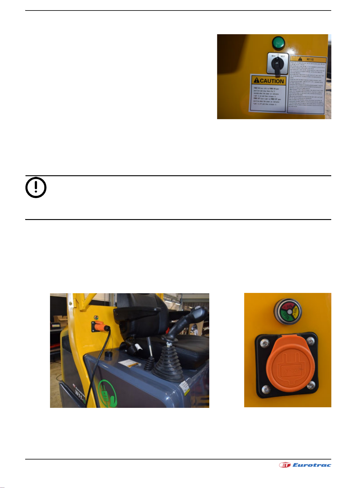
• Turn on the main power switch located at the left side, behind
the seat. Turn this for 3 seconds to the left till the green light
turns on (see picture).
• Turn on the ignition switch on the side of the dashboard.
• Release the handbrake by pressing the button on the dashboard.
• Move the transmission shift lever into the required position, Forward or Reverse.
• Press the acceleration pedal slowly with your feet. The wheel loader will move to the selected direction.
• To slow the wheel loader, slowly release the accelerator pedal and press the left brake pedal. For an emergency
stop, release the accelerator pedal and press brake pedal. By releasing the accelerator pedal slowly or quickly,
the wheel loader can be controlled by flat or sharp braking. Press the left-pedal when emergency brakes.
The main power switch will turn of automatically when there is nobody on the driver seat for longer than 60
seconds.
CHARGING THE BATTERY
The Eurotrac W11-E comes standard with a built-in 220V battery charger. With the supplied cord it is easy to
connect to the machine and charge via a 220V connection. The status of the battery can be easily seen on the load
indicator.
Red = less than 80% | Yellow = 80% | Green = 100% loaded |Max loading time = 6 hours
Page 15/72
October 2019W11E | Operation manual

WARNING
The maximum duration of control for an operator should not exceed 6h per day.
WARNING
WARNING
WARNING
WARNING
WARNING
Match driving speeds to loads being towed and weather conditions. Slow down when towing heavy loads and when
road surface is wet or icy, especially on grades.
When loading the goods, the speed should be lowered to 5km/h and the bucket should be raised to the
transportational position (about 20cm from the ground).
In the course of ramping on the road (uphill) for the temporary parking, drivers are not allowed to leave the driver's
seat and change gear switch. Right foot should press the micro-pedal gently to remove any slipping phenomenon
due to technical reasons. At the same time pull up hand brake. Downhill for the temporary parking. Drivers are not
allowed to leave the driver's seat and switch to a reverse gear shift, right foot should press the micro-pedal gently
and park slowly, at the same time pull up hand brake.
Parking on the ramp is not allowed. If necessary the car should be parked on a slope (due to breakdowns), you must
pull hand brakes and pad the wedge under wheels of the loader.
Make sure the roll cage arises and fixed before driving, it can‘t protect the driver if the roll cage don‘t arise or fixed
insecure.
LOADING INSTRUCTION
• Lift devices and attachments (bucket is standard) are only used for a specified purpose.
• Ensure the wheel loader is secure and is within the rated drawbar pull of the loader (See “General preventive
measures“).
• Ensure the rapid removal device in a locked position before filling.
• When driving with a load, the speed should be reduced to 5 km/h.
Page 16/72
October 2019W11E | Operation manual

• When driving with a load, the bucket should be raised to the transformational position (about 20cm from the
NOTE
WARNING
WARNING
WARNING
WARNING
WARNING
ground).
• When driving on the ramp, goods shall be towards the uphill direction. U-turns and parallel driving on ramps
must be avoided.
• Only operate the machine when having clear and unobstructed view.
• When uninstalling, raise the bucket to an appropriate height, as carefully as you can accurately to drive the
wheel loader to the truck or the place for goods storage; Carefully control the master control lever, uninstall,
reset; Confirming that the bucket and the truck (shelf) is completely separated, the loader moves slowly back
to leave the shelf.
• When reaching the parking spot, shift it into neutral position, raise the parking brake, and turn off the ignition
switch.
Safe and efficient loading, depends entirely on the operator. If you are an experienced driver, the following rules
will refresh your memory. If you are a student, they will help you to become a professional driver.
Only qualified and licensed drivers allowed to drive.
Before starting loading, please make sure the cylinder of the quick removal device is in the locking position, set the
locking tools, and cut the two-way ball valve off.
When driving on the ramp (forward or backward), goods shall be towards the uphill direction. Driving or u-turn
ramping on the horizontal should be avoided.
When the goods are in a lifting state, do not leave the loader.
When the goods are in a lifting state, the loader can not turn around and can not run at high speed.
Page 17/72
October 2019W11E | Operation manual

2.1.1 Joystick for lifting frame
WARNING
Accident hazard due to wheel loader tipping! Keep the lifting frame lowered during transport.
Accident hazard due to uncontrolled lifting frame movement!
Only operate the lifting frame and attachment from the driver's seat!
Always work calmly and cautiously. Hectic and rapid operation leads to accidents.
Always lower the lifting frame during interruptions and at the end of the shift.
Lifting frame movements are controlled by the joystick. The joystick
is located to the right of the driver's seat.
Lifting frame
• Move the joystick backwards: the lifting frame rises.
• Move the joystick forwards: the lifting frame lowers.
• Move the joystick 2 step forwards: the lifting frame is now in the
floating position (optional extra).
Attachment
• Move the joystick left: the attachment tips inwards.
• Move the joystick right: the attachment tips outwards.
Page 18/72
October 2019W11E | Operation manual

2.1.2 Joystick for auxiliary hydraulics
WARNING
Hazard due to hydraulic system overheating! Ensure that the auxiliary hydraulics joystick is always in the "zero
position" when the auxiliary hydraulics are not required. Lock the auxiliary hydraulics joystick when it is not
required. (To do this, press the joystick down firmly until it locks into place. To unlock, you must pull the joystick
back up firmly.) Avoid soiling. Ensure that the hydraulic connections are clean!
The additional hydraulics on the front arm: press the auxiliary hydraulics button and move the joystick to the left
and right. The auxiliary hydraulics can be very precisely controlled. Take care to use the joystick carefully.
Eurotrac W11 Eurotrac W12/W13
• Push the joystick to the left (and simultaneously press the auxiliary hydraulics button):
The left connection is the pressure side, the right is the return.
• Push the joystick to the right (and simultaneously press the auxiliary hydraulics button):
The right connection is the pressure side, the left is the return.
This may vary from model to model. Please always check this before using the wheel loader with optional
equipment.
Auxiliary hydraulics
This can be operated using an additional lever with switching valve. Let yourself be instructed by qualified personnel
and complete this manual here.
Replace attachment
1. Push the small handle of multi-way valve to the left to retract the locking lever.
2. Lower the working device and tilt it forward to the appropriate position.
3. Connect the hook in the attachment.
4. Hoist and tilt working device.
5. Push the small handle of the multi-way valve to the right to make the locking lever extend and insert the
mounting hole under the fitting.
6. The two three-way valve rotates 90°, cut off the lock cylinder oil.
Page 19/72
October 2019W11E | Operation manual

Remove the attachment
WARNING
WARNING
WARNING
WARNING
WARNING
The step is reversing as changing attachment step.
Lifting devices and tools are only used for a specified purpose. Drivers must comply with the correctly and use the
lifting devices and tools. Do not enter or reach into the space between the arm and the frame.
Before the operation of hydraulic systems, check if the functions of the various hydraulic joysticks are correct.
Before disassemble the pipe of attachment, should release the rest pressure of this pipe, then disassemble the quick
change connector. The detailed method of release rest pressure is: swing the first valve handle (small handle) of
multi-valve left and right side several times.
Even if the engine flameout can also lower the lifting devices and tools.
If the tool is not delivered together with the loader, it can be only used after the authoritarian of stability and load
capacity by the dealer of EUROTRAC.
General preventive measures
• Do not operate any levers or pedals if anyone is in any position to be hurt by the machine's movement.
• Pay extra attention when working in narrow congested areas or in case of blind travel.
• Always look around in all directions BEFORE changing your direction of travel.
• Always follow all safety rules or each particular site during operation.
• Maintain a running speed which is compatible with the load and the ground conditions.
Page 20/72
October 2019W11E | Operation manual

• Slow down when approaching corners
• Observe pedestrians carefully and do not follow the vehicle in front too closely.
• Do not brake sharply and only select neutral once the loader has effectively stopped.
• Maintain a safe distance from the edge of loading wharf.
• When turning, pay close attention to the trajectory of the buckets.
• Make sure that bridges and ramps are able to withstand the weight of the loader and the load being towed.
• Before climbing or descending from vehicles (trucks, trails etc), ensure that the adequate precautions are been
taken to avoid all movements including the dumping.
• Stop, look at and listen when arriving to a rail way then to cross it in diagonal, slowly and only to the authorized
points.
• Always park at more than 2,5m of the rails.
• Hold the wheel steering in hand during the operation.
• When loading a larger load, more space for the overtaking of parked vehicles, objects or pedestrians should be
predicted.
• Never overtake another vehicle on crossroad or on bifurcations or when something affects the visibility for you.
• Never drive in elevators, truck or other until you have received the order and you are sure that they can stand
the combined weight of loader and the load.
• Doesn't brake roughly.
• Pay attention to the driving speed and be careful to the pedestrians approaching and other vehicles and to the
passage heights.
• Slow down on wet, irregular grounds and in the turning.
• Remove all objects in your way.
• On the crossroad, in the passages and the corridors, slow down and horn and drive on the right side of the road.
• Be careful to the pedestrians which can appear suddenly in the way.
• If your trip involves crossing road bridge, ensure they are secure and are strong enough to withstand the
combined weight of the loader and load.
• When approaching the destination, reduce the speed to ensure a smoothly slow stop in the far enough
distance. A sudden halt could cause the load displacement.
• In the event of an emergency, first place the load on the ground before you proceed with further action.
• Report any mechanical or electrical irregularities immediately.
• Always be alert; Watch out for pedestrians and never drive too close to the vehicles in front.
• Travel at a speed consistent with load and road conditions.
• Never operate the loader with any part of your body outside of the operator's compartment.
• DO NOT leave the driver's cab with the loader running.
• ALWAYS properly shut down the loader before leaving the loader.
• ALWAYS park the loader on solid, level ground.
On severe slopes
• ALWAYS park the loader perpendicular to the steepest slope to prevent accidental movement.
• Use proper flags, warning marks or barriers when parking in areas of traffic.
• Do not park your vehicle in the access points where obstruct the fire brigade.
• During parking, use the parking brake and put the key on the STOP position.
• If the tractor must leave with nobody watching it, remove the ignition key.
• Never park your vehicle on a slope.
• If it is necessary to park tractor on a slope (break down etc), use the wedge under the wheels of loader.
• Do not drive while the rear cover is open.
• Don't make dangerous modifications to lithium batteries.
Page 21/72
October 2019W11E | Operation manual

WARNING
If problems or equipment malfunctions occur while operating the loader, it must be properly to shut down and
WARNING
correct the problem.
Continuing to use malfunctioning equipment can not only be unsafe for the operator and other personnel, but can
lead to further damage to the loader as well.
In case of an accident, report to your superior immediately. Never neglect an injury even if it appears insignificant,
go immediately to the doctor, which could avoid complications.
AREA RISK SAFETY STEPS
CAUSES OF FAILURE
ENTIRE MACHINE
WHAT CAN HAPPEN IF PRECAUTIONS
AND SAFEGUARDS ARE NOT OBEYED
A moving wheel loader can run over or
crush body parts between tractor and
other object and cause irreparable
injury or death.
HOW TO PREVENT THE FAILURE
Keep away all people from around tractor and
always switch off the engine before leaving
the driver's cab.
DRIVING STATION
UNDERNEATH
DURING SERVICE
MOTOR
LITHIUM BATTERIES
ROLLING OR ROLLING
OVER OF VEHICLE
TIRE
Personnel injuries may happen if parts
of the body or members (hands, legs,
etc.) are outside of the driver's cab.
Unit lifted for service could fall and
injure or kill personnel around.
Hot (motors) will cause severe burns
and cause serious injuries if persons
are struck by moving parts or caught in
belts.
Lithium batteries can explode when
dangerous operations such as welding
and drilling. Contact with a battery
socket or all unprotected electronic
parts (or when removed) can result in
an electrical shock.
When a vehicle rolls or rolls over, do
not jump off, as the loader is installed
with a safety roll cage. Jumping of may
lead to the drivers death.
Welding near the tire may damage the
tire or lead the lead an explosion and
bring damages or dangers for people.
Keep head, arms, hands, legs and feet inside
the operator's compartment all the time.
If loader must be lifted for service, it must be
securely blocked so that all 4 (four) wheels
may safely turn.
DURING SERVICE: Turn off the main power. If
maintenance operation requires starting
motor, personnel should avoid contact with
rotating equipment. Disconnect the lithium
battery power supply to prevent accidental
startup. Be careful to avoid hot surfaces.
Lithium batteries should be well ventilated
before use, especially when welding near
them. When operating a lithium battery, wear
protective clothing, protective gloves and
protective glasses. Avoid removing plastics
and avoid contact with electrical parts.
At this point your hands should hold the
steering wheel, and feet hold the mounting
brackets.
If welding has to be done on the wheel or near
the wheel, remove the tire first.
Page 22/72
October 2019W11E | Operation manual

• To avoid loaders accidental movement, put some wedge blocks under tires when provide services and
maintenance vehicles.
• Always stop the engine when working after the wheels.
• Don’t try to repair the machine by yourself if you haven‘t been approved by EUROTRAC.
• Don't carry out any modification that is not showed in the section 3. “MAINTENANCE PARTS“ of this manual.
• EUROTRAC is not responsible in case of any modification, addition or combination with equipment from
another origin, which maybe cause danger.
• Don‘t change the structure and performance of vehicle when EUROTRAC is not informed.
Electrical equipment
• Do not change the electronic- or hydraulic factory settings to prevent short circuit when working in the
electrical system disconnecting the battery; similarly, it also can to prevent unexpected start-up when the
engine is working.
• Do not check battery status near open fires, especially when lithium batteries are recharged.
• Do not smoke in the lithium battery charging area.
• No unauthorized disassembly by non-professional personnel.
• Do not tamper with the battery.
• Do not use wires to directly short circuit the outlet of the battery pack.
• The charging and discharging shall not exceed the maximum current specified in the technical parameters.
• Keep the battery away from the hot heat source.
• Avoid charging in direct sunlight.
• Do not keep the battery in a damp place or in water.
• Do not force the battery or make it fall from high altitude.
Welding
Before any arc welding operation on the loader, the operation is as follows:
1. Disconnect the battery.
2. Disconnect electronic control system and electrical equipment.
3. Place the ground clamp where the soldering is done as close to the ground as possible.
Page 23/72
October 2019W11E | Operation manual

2.2 Specifications and performance
TECHNICAL PERFORMANCE PARAMETER
Type of loader W11E
Motor parameters
Manufacturers
Motor model
Maximum power 11Kw- 48V
Electrical systems SME Controller
Operating voltage 12V
Battery capacity 60V/400Ah (19.2KwH)
Battery type Dry Lithium
Self-weight (with standard bucket) 2300
Rated load (0.2m³ bucket) (kg) 650
Maximum lifting force (DaN) 1100
Cargo bucket overturning Load (ginseng ISO8313)
Vehicle Straight line (kg) 1250
Vehicle articulated (kg) 900
Vehicle parameters
Walking speed (km/h) 0-14
Hydraulic Oil (L) 30
Hydraulic system
Hydraulic working elements
Working pressure (BAR) 170
Dimensions (mm)
A Protection device width 950
B Off-ground clearance 178
C Tire Center Width 803
DTotal width 1104
E Maximum operating height 3480
F Maximum height of bucket fulcrum 2900
G Bucket horizontal height 2649
H Tipping height 2228
I Tilting working distance (tilting state) 690
J Shovel depth 120
K To the center of the lifting pin of the bucket 550
L Axle distance 1476
M Rear overhang 923
N Without bucket overall length 2950
O With bucket overall length 3815
Q Seat height 1208
Page 24/72
October 2019W11E | Operation manual

TECHNICAL PERFORMANCE PARAMETER
W11E
S 860kg
T 800kg
U 600kg
V 480kg
R To protect device top height 2268
S Angle of max lifting height 48°
T Max tilting angle 45°
U Turning corner of level position surface 48°
VDeparture angle 23°
W Turning corner 45°
X Maximum turning radius 2530
Y Out edge radius 2220
Z Inner turn radius 1110
Load center distance = 400, load capacity of W11E cargo fork:
Page 25/72
October 2019W11E | Operation manual

Page 26/72
October 2019W11E | Operation manual

2.3 Transport procedures
WARNING
NOTE
Hiking up
In the position marked with the lifting mark, use a reliable cable lifting loader.
Lithium battery
Switch off the connector of lithium battery.
Leave the lithium battery in battery box.
Check
Make sure the main power switch is disconnected.
Fixing
Tighten the front and rear frame with a locking plate.
Use a strong rope at the vehicle bundling point and take care not to damage the paint surface.
Tighten the front and rear wheels with wedge blocks.
2.4 Trailer procedure
When the loader needs rescue, only the short haul of the loader is allowed, but the following steps should be
followed before dragging the loader.
Draught loaders are no longer capable of braking and steering.
Trailer steps
• Place the shim (wedge) at the slip side behind the wheel.
• Discharge cargo and equipments.
• Start the tractor
• The tractor (which has sufficient traction and braking force) is connected to the towing pin (which must be
strong and fixed reliably) at the counterweight at the rear of the loader through a rigid traction bar.
After the trailer
Wedge a block against the sliding edge of the wheel.
The brake function of the loader should be checked after maintenance.
The towing point when being towed is at the rear counterweight. The maximum force allowed for these points is
20KN.
Page 27/72
October 2019W11E | Operation manual

NOTE
This machine can be used for short-distance dragging unpowered trailers:
1. The traction device is located at the trailing part of the rear of the counterweight.
2. The maximum traction of the W11E is about 7.5KN.
3. Maximum traction speed ≤ 5km / h.
4. Only allowed to be pulled by rigid drawbar.
5. Not for long distance traction.
2.5 Stored procedures
Once a month Indefinite duration
Travel motor No special attention is required. Remove the motor and cover it with protection.
No special attention is required. By removing the drain plug under the differential
Drive axle
Tire
Lubricating oil
Liquid
Wheel bearing
Lithium battery
The loader must be raised or
the axles are padded to prevent
the tires from coming into
contact with the ground. The
tire pressure must be reduced
to 15PSI.
Make sure all the points are
lubricated with special oil.
All levels must be checked and
filled if necessary.
Wheel bearings must be
repackaged.
Disconnect the lithium battery
terminal.
housing to drain the drive shaft, the plug is reloaded
after it is finished.
The loader must be raised and the axle is padded to
prevent the tire from contacting the ground. The tire
pressure must be reduced to 15PSI and sprayed with
rubber preservatives.
Make sure all the points are lubricated with special oil.
Drain all the liquid.
Wheel bearings must be repackaged.
Lithium batteries must be removed and stored
separately. Lithium batteries must be stored in a cool,
dry place and must not be exposed to direct sunlight.
If a lithium battery is stored in an open area, it must be
covered to protect it from contaminants and moisture.
Lithium-ion batteries must be recharged slowly every
one or two months.
Note:
1. The ambient temperature range of this loader is -30°C-50°C
2. Long-term storage may damage the gaskets in the hydraulic system.
Page 28/72
October 2019W11E | Operation manual

3. MAINTENANCE PARTS
WARNING
WARNING
CAUTION
3.1 General description
By definition, preventive maintenance, including regular maintenance and inspection operations, is to prevent
failures. Preventive maintenance operations allow the operator to detect wear or deterioration on the equipment
early.
3.2 General cleaning instructions
When thoroughly cleaning the loader, use normal methods (do not use high pressure cleaning) to avoid wearing
electrical equipment, safety equipment, trademarks and labels. When cleaning electrical components, it is
recommended to blow dry air with a maximum pressure of 29 PSI. When cleaning mechanical parts, first clean the
oil with a degreasing product and then dry it with dry air. Lithium batteries must be protected from chemical
reactions and severe damage to current branches.
Solutions may affect the skin, eyes and respiratory tract. Use only in well ventilated areas.
Avoid breathing under water vapor for a long time. Keep away from sparks and flames.
To avoid possible personal injury, do not perform cleaning and drying steps with more
than 30 PSI air pressure. Use eye protection and defense and approve air hose nozzles.
Before removing the hydraulic hose, the filler cap must be loosened and the residual pressure in the tank must be
released.
Do not immerse electronic components, packaging, or rubber, plastic, or plastic parts in a cleaning solvent.
Wipe the parts with a clean cloth. Cleaning solvents can affect materials and cause serious damage or damage to
parts.
• Wash parts in a tank that specializes in cleaning parts or spray the cleaning agent on the surface of the part.
• Rinse or spray to clean the parts. If necessary, brush with a non-metallic brush.
• Except the bearings, dry the parts with compressed air after cleaning.
• Do not use metal scrapers, wire brushes, grinding wheels, or abrasive compounds when cleaning parts unless
there are special requirements for maintenance procedures.
• Clean electronic parts such as relays or switches with a cloth dampened with cleaning solvent.
• Clean the heat exchanger with a steam cleaner or a pressure washer and soap. Do not use the aluminum or
copper cleaner that will affect it.
• Clean the outer surface of the battery with a weak solution of soda and water.
Page 29/72
October 2019W11E | Operation manual
• Use a non-metallic brush to remove corrosion from the lithium battery cable terminals.
WARNING
•Use 1∕4 pound of soap to add a gallon of water to clean the painted surface of the vehicle.
• Clean with clean water and dry with linen or air.
First maintenance program
• First time maintenance must be performed between 10 and 125 hours of operation.
• For motor maintenance, see the motor operating manual (this unit comes with the motor operating manual).
• Check for oil leaks and correct if necessary.
• Check hoses and connections and check the wires.
• Check the rim nut torque after 10 hours of operation, also for more than 50 hours and check the rim nut torque
after each wheel change.
3.3 Service
3.3.1 Preparation for use
Lithium battery
Brake system
Travel motor
Rear axle and reducer Check the axle oil level and refuel if necessary.
Tire Air Refill
Hydraulic oil
Due to pressure in the hydraulic tank, loosen the filler cap and slowly release the pressure before opening.
Connect the lithium battery cable. If it is disconnected, connect the positive pole first.
Make sure the lithium battery is fully charged.
Check if the brake fluid leaks.
Slowly start the vehicle, release the throttle, and step on the jog pedal to check the
brake effect.
Check that the travel motor is operating normally.
Check the line connection.
Check the tire air pressure and inflate if necessary.
After removing the wheel, it is recommended to tighten the nut: 2 hours, 50 hours,
every 200 hours.
Recommended wheel nut tightening: 372N.m
Recommended wheel pressure W11E: 3.0Bar
Check the hydraulic tank level and the lowest level is indicated on the filter at the
filler.
Grease points
Add in each grease point
1. All joint bearings
2. All hinges
3. All bushings
Page 30/72
October 2019W11E | Operation manual

3.3.2 Regular maintenance form
The loader must be maintained according to the following table
Lithium battery capacity x
- 3.0/5.2BAR tire pressure x
Daily inspection
Weekly or
every 50 hours
Monthly or
every 200 hours
Every two months or
every 400 hours
Every six months or
every 1200 hours
Every year or
every 2400 hours
Tire tread, check
Remove foreign objects such as stones in gaps
x
Adjust headlights, aim correctly x
Work light, tail light, double jump light, work light and turn signal
operation
x
Cab sign lights, heaters, wiper operation and cab lights (if installed) x
Horn x
Hydraulic oil level x
372N.M (*) Wheel nut fastening x
Drive axle fixing bolts, tighten when needed x
Tighten the cylinder head bolts and all nuts and bolts. Adjust the
specific torque to the specific requirements if necessary.
x
Drive axle oil level x
Replace the axle oil (replace the oil after 50 hours for the first time;
then replace it once a year)
x
Hydraulic oil x
Hydraulic suction oil filter x
Parking brake x
Handbrake on the engine has to be adjusted when the power is off. x
Hydraulic oil x
Driver seat adjuster x
Pedal point x
Oil all greasing points x
Cab door lock (if installed) x
Check motor idle speed and speed, adjust if necessary x
Replace the brake pads of the parking brake x
The hydraulic oil in the hydraulic system drains out, cleans the system
and refills the new hydraulic oil.
x
Drive axle gear oil replacement. x
(*):The tire nut must be re-adjusted to the position: 372N.M. After each replacement of the wheel, and at any time the nut has
been loose, and maintenance is required at this specified time interval.
Page 31/72
October 2019W11E | Operation manual

Proper regular maintenance will allow the operator to avoid any mechanical failure. Pay attention to the frequency
CAUTION
of the lubricating oil.
Lithium battery inspection and replacement
Use and maintain the battery according to the Lithium Ion Power Battery Installation Operation and Maintenance
Manual provided by the lithium battery manufacturer.
Replace the lithium battery
1. Place the loader in a safe and open horizontal position.
2. Disconnect the main power switch.
3. Use a wooden wedge on the front and rear wheels to prevent the vehicle from moving when replacing the
battery.
4. Remove the rear bonnet, rear frame cover, traction seat assembly, battery fixing plate, remove the lithium
battery lever and disconnect all the connectors with the lithium battery and affect the lithium battery
replacement circuit.
5. Use a forklift and a special guide to command the forklift to operate. Use the shovel foot from the rear of the
loader to gently shovel from under the battery, slowly raise the shovel foot until the battery leaves the base
and pour the fork backwards. The lithium battery can be completely removed.
6. Barbaric operations are strictly prohibited during operation.
7. The replaced lithium battery should not be discarded at will, and it should be recycled by the lithium battery
manufacturer.
8. The above operation is reversed when installing a lithium battery and when restoring the loader.
Tire replacement
1. Never enter the loader after the loader has been jacked up by the jack.
2. Torque tighten the hub nut, 372N.M.
3. Adjust tire pressure after tire replacement, W11E: 3.0Bar.
4. Do not increase the air pressure beyond the specified range.
Front wheel
1. Place the loader in a horizontal position.
2. Use a parking brake and insert a jack under the body.
3. Use a jack to lift the body until the tire is almost off the ground and loosen the hub nut.
4. Use a jack to jack up the body so that the tire is off the ground and remove the hub nut and wheel.
5. After repairing and replacing the tires, repeat the reverse process to install the wheels. Tighten the hub nut
evenly in the diagonal direction in order.
6. Check and adjust the tire air pressure after the wheel is installed.
Page 32/72
October 2019W11E | Operation manual

Hydraulic oil replacement
WARNING
CAUTION
CAUTION
The front working unit should be lowered completely before draining the hydraulic fluid.
1. Drive the loader to the trench.
2. Lower the front working device completely.
3. Place a container on the bottom of the loader.
4. Open the rear cover.
5. Unscrew the hydraulic oil filler port.
6. Unscrew the suction filter.
7. Remove the drain plug of the hydraulic tank.
8. Fully drain the hydraulic oil.
9. Wipe the area near the drain plug.
10. Reinstall the drain plug.
11. Make sure the replaced oil filter is filled with oil to avoid damages.
12. Tighten the filler cap.
13. Fill the oil filter port with the hydraulic oil until it is full.
14. Tighten the oil filter cover back.
15. Start the engine, run for a while in the idle state, repeatedly turn the steering wheel to the left and right to the
maximum corner several times, let the car slowly drive for dozens of meters and lift down several times, and
check the oil level again.
Discarded oil should be disposed of in accordance with relevant regulations. Avoid skin contact with oil. Also don't
let the oil flow into the sewer or flow to the ground.
3.3.3 Oil & Lubricant
Hydraulic system
Model Specification Caltex HDZ-46
W11E 66L
Drive axle
Model Specification Gear Oil L-CKC 220
W11E 2L
The oil mentioned above is used under normal weather conditions. For a coldest or hottest country, please contact
EUROTRAC or dealer.
Page 33/72
October 2019W11E | Operation manual

NOTE
1. When replacing hydraulic components, in order to avoid component deterioration, it is essential to filter and
inspect hydraulic fluid before use.
2. Do not mix two oils.
Drive axle
Type NLGI grade No. 3 lithium grease
Rod end joint bearing
Type Lithium base grease every 500 hours.
Page 34/72
October 2019W11E | Operation manual

3.4 Troubleshooting
3.4.1 Kinetic energy reduction
Page 35/72
October 2019W11E | Operation manual

3.4.2 Drive axle
Page 36/72
October 2019W11E | Operation manual

3.4.3 Brake system
Page 37/72
October 2019W11E | Operation manual

3.4.4 Lithium battery
Page 38/72
October 2019W11E | Operation manual

FIGURE 1: W11E HYDRAULIC SCHEMATIC
Page 39/72
October 2019W11E | Operation manual

FIGURE 2: ELECTRICAL SCHEMATIC
Page 40/72
October 2019W11E | Operation manual

FIGURE 3: BODY LOGO LAYOUT
1. Hydraulic control tips 19. Brandname sticker
2. Model trademark 20. Read instructions for use
3. Parking brake sign (English) 21. Read the maintenance manual warning
4. Tire label 22. Make a trademark sticker
5. Tire pressure label 23. Lifting capacity sticker
6. Anti-slip mat 24. Anti-tip sticker
7. Vehicle nameplate 25. Vehicle nameplate - cab
8. Lifting label 26. Hydraulic oil label
9. Anti-sticker label 27. Seat belt label
10. Danger of crushing hand sticker 28. Anti-label
11. Fuel label
12. Water tank anti-scald label
13. Anti-cutting label
14. Greasing point indication
15. Noise statement label
16. Anti-slip mat
17. Reset button label
18. Transport fixed point label
Page 41/72
October 2019W11E | Operation manual
DAILY EQUIPMENT INSPECTION
WARNING
In the event of a problem, the operator should not attempt to repair and is responsible for immediately reporting
to the superior. Repairs must be performed by a professional.
Daily Equipment Inspection – W11E Loader
Car Number S/N: Date:
Operator:
[ ] Well [A] Commissioning completed [N] need to repair
[ ] Ensure that the travel motor and hydraulic motor are good.
[ ] Open the hydraulic tank cover and check the fluid level. Make sure the liquid level is within the operating
range and then close the lid.
[ ] Check the inflation pressure of each pneumatic tire. Wheel requirements 3.0BAR. Adjust tire pressure as
required.
[ ] Check for tread damage or wear. Remove the stone from the tread and report any damage, side tread
damage, or unusual wear.
[ ] Make sure the headlights are working properly.
[ ] Check other lights, including rear, tail stop lights and directional lights, if the vehicle is equipped with these
lights.
[ ] Make sure that the heater, wiper and cab ceiling lights in the cab work properly (if installed).
[ ] Operate the horn, it can be clearly heard under noisy sound.
[ ] Make sure all controls are good. Report any fault control and do not use the device until it is fully repaired.
[ ] Correct the driver's seat position and adjust it to suit your requirements.
Eurotrac
Stougjesdijk 153
3271 KB Mijnsheerenland
The Netherlands
Tel. + 31 (0) 186 612 333
info@eurotrac.nl
Page 42/72
October 2019W11E | Operation manual

4. SME ELECTRONIC CONTROL SYSTEM
4.1 About warning, caution and information notices
Special attention must be paid to the information presented in Warning, Caution and other kinds of information
notices when they appear in this manual. Failure to follow those recommendations may result in dangerous
situations or in damages to the components, for which SME will not respond.
Warnings: A Warning informs the user of a hazard or a potential hazard which could result
in serious or fatal injury if the precautions or instructions given in the warning notice are not
observed.
Cautions: A caution informs the reader of a hazard or a potential hazard which could result
in a serious damage to the appliance.
Information Notices: An information notice contains additional, not essential pieces of
information to complete or to clarify the meaning of the paragraph they are placed into.
User Manual Reference: A User Manual Reference informs the user to look up specified user
manual for more details.
Interactive Documentation Tips: An advice about where to find the related section in the
Interactive Documentation
Page 43/72
October 2019W11E | Operation manual

4.2 Troubleshooting and fault codes
4.2.1 Fault levels
PRIORITY LEVEL ACTIONS
Main contactor opened
1 (HIGHEST) Blocking
2 Stopping
3 Limiting
4 (LOWEST) Warning
4.2.1 Fault list
Code Fault Level Family Possible Causes Set Condition Clear Condition
1 Over Voltage Blocking All • Battery resistance too high while
regenerating.
• Battery disconnected while
regenerating.
2 Under Voltage Blocking All • Battery seriously damaged or
exhausted.
• Battery resistance too high.
• Battery disconnected while driving.
• Blown key-switch fuse.
• External load drains power from
battery.
3User
Over Voltage
4User
Under Voltage
5Inverter 1
Over Current
6Inverter 2
Over Current
7- - All - - -
Blocking TAU
System
Blocking TAU
System
Blocking All • External or internal short-circuit
Blocking All • External or internal short-circuit
• Battery resistance too high while
regenerating.
• Battery disconnected while
regenerating.
• Too low voltage level defined by the
user
• Battery serious damaged or
exhausted.
• Battery resistance too high.
• Battery disconnected while driving.
• Blown key-switch fuse.
• External load drains power from
battery.
• Too high voltage level defined by the
user.
between U1, V1 or W1 AC motor’s
phases.
• Incorrect motor 1 parameter/s.
• Inverter 1 power module damaged.
between U2, V2 or W2 AC motor’s
phases.
• Incorrect motor2 parameter/s.
• Inverter 2 power module damaged.
Key-switch voltage or
capacitors voltage is
above the maximum
level allowed for the
controller.
Key-switch voltage is
below the minimum
level allowed for the
controller.
Key-switch voltage is
above the maximum
level defined by the
user.
Key-switch voltage is
below the minimum
level defined by the
user.
Inverter 1 phase current
exceeded its current
limit.
Inverter 2 phase current
exceeded its current
limit.
Motors disabled
Outputs disabled
Main contactor closed
Motors stopped
Outputs enabled
Main contactor closed
Motors limited
Outputs enabled
Main contactor closed
Motors enabled
Outputs enabled
Bring key-switch voltage
below over-voltage limit
and then cycle key
switch.
Bring key-switch voltage
above under-voltage
limit and then cycle key
switch.
Bring key-switch voltage
below user over voltage
limit and then cycle key
switch.
Bring key-switch voltage
above user under voltage
limit and then cycle key
switch.
Cycle key switch.
Cycle key switch.
Page 44/72
October 2019W11E | Operation manual

Code Fault Level Family Possible Causes Set Condition Clear Condition
8Inverter 1
Over
Temperature
9Inverter 2
Over
Temperature
10 Inverter 1
High
Temperature
11 Inverter 2
High
Temperature
12 Inverter 1
Under
Temperature
13 Inverter 2
Under
Temperature
14 Inverter 1
Current Sensor
Fault
15 Inverter 2
Current Sensor
Fault
16 - - All - - -
17 Inverter 1
Temp Sensor
Fault
18 Inverter 2
Temp Sensor
Fault
19 Motor 1
Over
Temperature
20 Motor 2
Over
Temperature
21 Motor 1
High
Temperature
Blocking All • Operation in high temp environment.
• Operation with high load.
• Wrong mounting of the controller
heat sink.
• Wrong working of controller cooling
system.
Blocking All • Operation in high temp environment.
• Operation with high load.
• Wrong mounting of the controller
heat sink.
• Wrong working of controller cooling
system.
Limiting All • Operation in high temp environment.
• Operation with high load.
• Wrong mounting of the controller
heat sink.
• Wrong working of controller cooling
system.
Limiting All • Operation in high temp environment.
Blocking All Operation in low temp environment. Inverter 1 power
Blocking All Operation in low temp environment. Inverter 2 power
Blocking All • Leakage current due to motor 1 stator
Blocking All • Leakage current due to motor 2 stator
Stopping
Stopping All Inverter 2 internal temperature sensor
Stopping All • Motor 1 temperature is too high.
Stopping All • Motor 2 temperature is too high.
Limiting All • Motor 1 temperature is too high.
All Inverter 1 interna
• Operation with high load.
• Wrong mounting of the controller
heat sink.
• Wrong working of controller cooling
system.
short-circuit.
• Controller’s sensor faulty.
short.
• Controller’s sensor faulty.
l temperature sensor
not connected or shorted.
not connected or shorted.
• Wrong Motor 1 thermal probe type or
input.
• Motor 1 thermal probe not connected
or shorted input.
• Wrong Motor 2 thermal probe type or
input.
• Motor 2 thermal probe not connected
or shorted input.
• Wrong Motor 1 thermal probe type or
input.
• Motor 1 thermal probe not connected
or shorted input.
Inverter 1 power
module temperature
above +100°C.
Inverter 2 power
module temperature
above +100°C.
Inverter 1 power
module temperature
above +80°C.
Inverter 2 power
module temperature
above +80°C.
module temperature
below -40°C.
module temperature
below -40°C.
Current sensor of
inverter 1 has an invalid
offset reading at key on.
Current sensors of
inverter 2 have an
invalid offset reading at
key on.
Difference between
inverter 1 and
microprocessor temp
greater than 70 °C.
Difference between
inverter 2 and
microprocessor temp
greater than 70 °C.
Motor 1 temperature is
above the motor over
temperature parameter
setting.
Motor 2 temperature is
above the motor over
temperature parameter
setting.
Motor 1 temperature is
above the motor start
cutback temperature
parameter setting.
Bring power module
temperature of inverter1
below 100°C and cycle
key switch.
Bring power module
temperature of inverter2
below 100°C and cycle
key switch.
Bring power module
temperature of inverter1
below 80°C.
Bring power module
temperature of inverter2
below 80°C.
Bring inverter 1 power
module temperature
above -40°C and cycle key
switch.
Bring inverter 2 power
module temperature
above -40°C and cycle key
switch.
Cycle key switch.
Cycle key switch.
Cycle key switch.
Cycle key switch.
Bring motor 1
temperature below over
temperature limit and
cycle the key switch.
Bring motor 2
temperature below over
temperature limit and
cycle the key switch.
Bring motor 1
temperature below start
cutback temperature and
cycle the key switch.
Page 45/72
October 2019W11E | Operation manual

Code Fault Level Family Possible Causes Set Condition Clear Condition
22 Motor 2
High
Temperature
23 Motor 1
Temp Sensor
Fault
24 Motor 2
Temp Sensor
Fault
25 - - All - - -
26 - - All - - -
27 Microprocessor
Over
Temperature
28 +5V Supply
Failure
29 +12V Supply
Failure
30 Encoder 1 Fault Blocking All • Motor 1 encoder failure.
31 Encoder 2 Fault Blocking All • Motor 2 encoder failure.
32 Driver Output 1
Open/Short
33 Driver Output 2
Open/Short
34 Driver Output 3
Open/Short
35 Digital Output 1
Open/Short
36 Digital Output 2
Open/Short
Limiting All • Motor 2 temperature is too high.
• Wrong Motor 2 thermal probe type or
input.
• Motor 2 thermal probe not connected
or shorted input.
Limiting All Motor 1 temperature sensor reads a
not permitted value.
Limiting All Motor 2 temperature sensor reads a
not permitted value.
Stopping All • Microprocessor faulty.
• Microprocessor temperature sensor
faulty.
Blocking All External load impedance on +5V
output is too low.
Blocking All External load impedance on +12V
output is too low.
• Motor 1 encoder faulty wirings.
• Motor 1 speed changes too quickly.
• Electromagnetic noise on the Motor 1
sensor bearing.
• Motor 2 encoder faulty wirings.
Motor 2 speed change very fast.
• Electromagnetic noise on the Motor 2
sensor bearing.
Blocking All • Open or short-circuit of driver output
1 load.
• Driver output 1 damaged.
Blocking All • Open or short-circuit of driver output
2 load.
• Driver output 2 damaged.
Blocking All • Open or short-circuit of driver output
3 load.
• Driver output 3 damaged.
Blocking All • Open or short-circuit of digital output
1 load.
• Digital output 1 damaged.
Blocking All • Open or short-circuit of digital output
2 load.
• Digital output 2 damaged.
Motor 2 temperature is
above the motor start
cutback temperature
parameter setting.
Motor 1 temperature
sensor value is out of
permitted range.
Motor 2 temperature
sensor value is out of
permitted range.
Microprocessor
temperature is above
125°C.
+5V supply is outside
the +5V±10% range.
+12V supply is outside
the +12V±10% range.
The difference of speed
evaluated between two
consecutive readings of
the encoder is above
the fixed limit
The difference of speed
evaluated between two
consecutive readings of
the encoder is above
the fixed limit.
Driver output 1 is either
opened or shorted.
iver output 2
Dr
opened or shorted.
Driver output 3 is either
opened or shorted.
Digital output 1 is either
opened or shorted.
Digital output 2 is either
opened or shorted.
is either
Bring motor 2
temperature below start
cutback temperature and
cycle the key switch.
Check motor 1
temperature sensor and
cycle the key switch.
Check motor 2
temperature sensor and
cycle the key switch.
Cycle key switch.
Remove all external load,
bring +5V supply inside
range and cycle the key
switch.
Remove all external load,
bring +12V supply inside
and cycle the key switch.
Cycle key switch.
Cycle key switch.
Correct open or short in
driver output 1 load and
cycle key switch. If fault
condition is present
without load connected
replace the controller.
Correct open or short in
driver output 2 load and
cycle key switch. If fault
condition is present
without load connected
replace the controller.
Correct open or short in
driver output 3 load and
cycle key switch. If fault
condition is present
without load connected
replace the controller.
Correct open or short in
digital output 1 load and
cycle key switch. If fault
condition is present
without load connected
replace the controller.
Correct open or short in
digital output 2 load and
cycle key switch. If fault
condition is present
without load connected
replace the controller.
Page 46/72
October 2019W11E | Operation manual

Code Fault Level Family Possible Causes Set Condition Clear Condition
37 EEPROM Failure Blocking All Failure to read/write EEPROM memory. Error during read/write
operation in EEPROM
memory.
38 EEPROM
Corrupted
39 Driver Output 4
40 Precharge Circuit
41 Precharge Failed Blocking All • External load on capacitors.
42 Main Contactor
43 Main Contactor
44 Interlock
45 Static Return To
46 Static Return To
47 Tra
48 Hydraulic
49 Brake
50 Service Time
51 Low Battery
Open/Short
Fault
Welded
Did Not Close
Disabled
Off Traction
Off Hydraulic
ction
Th
rottle Fault
Throttle Fault
Throttle Fault
Expired
State Of Charge
Blocking All Wrong firmware version or parameters. Memory CRC doesn’t
match.
Blocking All • Open or short-circuit of driver output
Blocking All • Pre-charge circuit faulty.
Blocking All • Line contactor contacts are welded
Blocking All • Main contactor did not close after
Stopping TAU
System
Warning TAU
System
Warning TAU
System
Stopping TAU
System
Stopping TAU
System
Stopping TAU
System
Warning TAU
System
Limiting TAU
System
4 load.
• Driver output 4 damaged.
• Short on capacitors between +B
and -B
• Power module short-circuit.
• Pre-charge circuit faulty.
closed.
• Motor phases are not connected.
• An external wiring is providing voltage
to capacitors.
contactor’s coil has been powered
• Main contactor coils are not
connected.
• +B fuse is blown.
Interlock input is not active. Interlock input is not
Traction throttle or direction selector
are active at key on, after the
Emergency Reverse or a controlled stop
procedure.
Hydraulic throttle or Auxiliary input are
active at key on or after a controlled
stop procedure.
Traction throttle wiring/s (analog/
digital) are not connected.
Hydraulic throttle wiring/s (analog/
digital) are not connected.
Brake throttle wiring/s (analog/digital)
are not connected.
Service interval time has expired. Service timer has
Battery state of charge drops below the
setting parameters.
Driver output 4 is either
opened or shorted.
Pre-charge is too fast or
capacitors voltage is
fixed to zero during
precharge.
Pre-charge phase fails
to charge capacitors till
the key switch voltage.
Before closing main
contactor capacitors are
loaded for a short time
and voltage don’t
discharge.
The difference between
key switch and
capacitors voltage id
too high after the
contactor has been
powered.
active and line
contactor is open.
One or more traction
inputs are active at key
on, after an EMR or a
controlled stop
procedure.
One or more hydraulic
inputs are active at key
on or after a controlled
stop procedure.
A fault condition of
traction throttle is
detected. See throttle
type documentation.
A fault condition of
hydraulic throttle is
detected. See throttle
type documentation.
A fault condition of
brake throttle is
detected. See throttle
type documentation.
expired.
Battery state of charge
estimated is lower than
minimum setting.
Cycle key switch.
Download correct
firmware or restore
default parameters.
Correct open or short in
driver output 4 load and
cycle key switch. If fault
condition is present
without load connected
replace the controller.
Cycle key switch.
Cycle key switch.
Cycle key switch.
Cycle key switch.
Activate interlock input.
De-select all traction
inputs.
De-select all hydraulic
inputs.
Cycle key switch.
Cycle key switch.
Cycle key switch.
Reset service timer.
Bring battery state of
charge above reset
parameter setting and
cycle key switch.
Page 47/72
October 2019W11E | Operation manual

Code Fault Level Family Possible Causes Set Condition Clear Condition
52 Wrong
Parameter
53 Restart Required Warning All A parameter setting is changed and you
54 CAN
Bus Off
55 CAN
Open Circuit
56 CAN
Bad Wiring or
Short Circuit
57 - - All - - -
58 - - All - - -
59 - - All - - -
60 - - All - - -
61 - - All - - -
62 Net Heartbeat
Timeout
63 Net RPDO
Timeout
64 Mains Contactor
Close Command
Timeout
65 Blocking Request
From Master
66 - - All - - -
67 Net Startup
Timeout
68 Net External
Failure
69 Net Blocking TAU A TAU Node, Helper or Follower for the
70 Net
Mains Manager
Precharge Too
Slow
Blocking All Wrong value of a parameter setting is
entered.
need to restart the controller to
become it effective.
Stopping All • Short between L, H channels or H
Stopping All • H or/and L channel not connected.
Blocking All • Wrong cable wirings.
Stopping All Temporary loss of communication. Heartbeat hasn’t been
Stopping All Temporary loss of communication. At least one PDO hasn’t
Blocking TAU
Generic
Slave
Blocking TAU
Generic
Slave
Blocking All Net synchronization failure at startup. The Node hasn’t been
Stopping All Net synchronization lost. At least one Node has
Blocking TAU
System
channel and GND of CAN driver.
• Wrong cable wirings.
• Wrong baud rate configuration of one
node.
• Wrong cable wirings.
• All other nodes of the net not
powered up.
• Swap of L channel and GND of CAN
driver.
5 sec after pre-charge is ended up, the
power line is not ready (for master).
Master has requested a fault condition. Fault request is received
main contactor management, signals
powering sequence made by
that the
nager is wrong.
the Ma
A TAU Node, Helper for the main
contactor management, signals that
the precharge phase has been too slow.
Parameter setting is out
of permitted range.
Changed a parameter
setting.
Bus off condition
detected.
Messages not longer
received.
CAN bus
synchronization phase
failed.
received for the timeout
established by the user
through the CAN
configuration settings.
been received for the
timeout established by
the user through the
CAN configuration
settings (for standard
application and for
electric steering
application).
Pre-charge timer has
expired before the
master sends the power
ready request.
from master.
able to synchronize
itself to the network.
become not
operational.
The main contactor
Manager has executed a
wrong powering
sequence.
DC Bus voltage will not
increase after
discharging phase.
Bring wrong parameter
within correct range and
cycle key switch.
Cycle key switch.
Cycle key switch.
Cycle key switch.
Cycle key switch.
Cycle key switch.
Cycle key switch.
Cycle key switch.
Cycle key switch.
If needed, correct net
startup parameter and
cycle key switch.
Cycle key switch.
Cycle key switch.
Cycle key switch.
Page 48/72
October 2019W11E | Operation manual

Code Fault Level Family Possible Causes Set Condition Clear Condition
71 Net
Mains Manager
Closing Too Slow
72 Net
Mains Manager
Powering Alarm
73 CO
Synchro Failed
74 CO
Synchro Lost
75 Stopped
For System Fault
76 Blocked
For System Fault
Blocking TAU
System
Blocking TAU
System
Blocking All Net never synchronized At least one node of the
Stopping All Net synchronization lost At least one node of the
Stopping TAU
System
Blocking TAU
System
A TAU Node, Helper for the main
contactor management, signals that
the main closing phase has been too
slow.
A TAU Node, Helper or Follower for the
main contactor management, signals
that the main Manager has the
powering state machine alarmed.
Node stopped for system fault Node is stopped
Node blocked for system fault Node is blocked
The main contactor
doesn’t close.
At least one fault has
occurred on main
contactor Manager
controller.
net could be wrong
configured or switched
off.
net could be wrong
configured or switched
off during operation.
because another node
has a stopping/blocking
fault condition.
because another node
has a stopping/blocking
fault condition.
Check the cable which
command the contactor
and cycle the key switch.
Cycle key switch.
Check that all nodes are
switched on and have
right net configuration
before cycle key switch.
Check that all nodes are
correctly supplied and
have right net
configuration before
cycle key switch.
Reset system fault
stopping condition or
verify system faults
remapping configuration.
Cycle key switch.
Reset system fault
stopping condition or
verify system faults
remapping configuration.
Cycle key switch.
77 BMS
Wall Charge
78 BMS Stop Stopping TAU
79 BMS
Fault
80 BMS
Limiting
81 Steering Sensor
Fault
82 Digital Inputs
Overvoltage
83 Programming
Required
84 - - All - - -
85 - - All - - -
86 - - All - - -
87 - - All - - -
88 - - All - - -
89 - - All - - -
90 - - All - - -
91 - - All - - -
92 - - All - - -
93 - - All - - -
94 - - All - - -
Blocking TAU
System
System
Blocking TAU
System
Limiting TAU
System
Limiting TAU
System
Blocking TAU
System
Blocking TAU
System
The BMS is recharging the battery. The TAU Node sets a
blocking fault.
The BMS requires a system stop. The TAU Node sets a Cycle key switch.
The BMS signals its faulty state. The TAU Node sets a
blocking fault.
The BMS requires a current limit. The TAU Node limits its
current to the required
value.
Steering sensor wiring/s (analog/
digital) are not connected.
Digital Input Supply has reached
dangerous value
A blocking fault is voluntary forced
during the programming to disconnect
the power from the Controller.
A fault condition of
steering sensor is
detected. See steering
sensor type
cume
do
Bad Wiring Verify the wiring.
Firmware Programming -
ntation.
Cycle key switch.
Cycle key switch.
Cycle key switch.
Cy
cle key
switc
h.
Page 49/72
October 2019W11E | Operation manual

Code Fault Level Family Possible Causes Set Condition Clear Condition
95 - - All - - -
96 - - All - - -
97 - - All - - -
98 - - All - - -
99 - - All - - -
100 Internal
Software Fault 1
101 Internal
Software Fault 2
102 Internal
Software Fault 3
103 Internal
Hardware Fault 1
104 Internal
Hardware Fault 2
105 Internal
Hardware Fault 3
106 Internal
Hardware Fault 4
107 Internal
Software Fault 4
Blocking All Internal software error(s) Internal error. Restore Eeprom default
and cycle key switch.
Warning All Internal software error(s) Internal error. Restore Eeprom default
and cycle key switch.
Warning All Internal software error(s) Internal error. Restore Eeprom default
and cycle key switch.
Blocking All Internal hardware error(s) Internal error. Cycle key switch.
Blocking All Internal hardware error(s) Internal error. Cycle key switch.
Blocking All Internal hardware error(s) Internal error. Cycle key switch.
Blocking All Internal hardware error(s) Internal error. Cycle key switch.
Warning All Internal software error(s) Internal error. Restore Eeprom default
and cycle key switch.
Page 50/72
October 2019W11E | Operation manual

5. AC SMARTMOTION AC-M2 OVERVIEW
AC-M2
5.1 Product description
The AC-M2 Controller is designed for lift trucks, handling machines and electrical vehicles using dual AC motors up
to 50kW.
Being based on high reliable DCB technology and exceptionally stable ITC Control Algorithm, AC-M2 Controller
ensures the best performance without use of mechanical differential.
AC-M2 Controller is suitable to control:
• 1 AC Traction motor + 1 AC Pump motor
• 2 AC Traction motor
The product is suitable for the following range of applications: Counterbalanced Lift Trucks, Reach Trucks, Order
Picking Trucks, Very narrow aisle Trucks, Cleaning Machines, Aerial Lifts, Tractors, Utility Vehicles.
Page 51/72
October 2019W11E | Operation manual
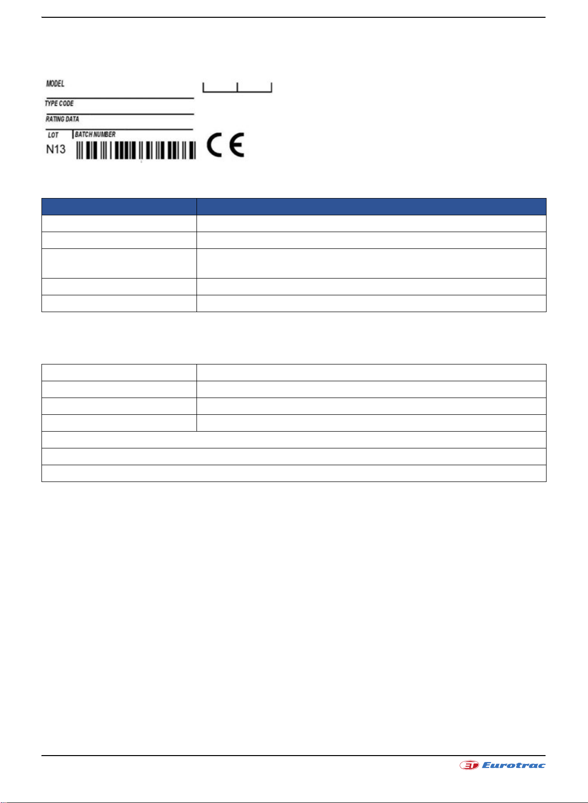
5.1.1 Product Indication Label
The product label shows important data regarding the specific product.
The meaning of each field is described in the table below.
Field Description
Model Product description.
Type Code SME code for the specific product.
Rating Data It contains the indication of the input voltages and the output currents
supplied by the product.
Batch Number Production batch number (the same value as in barcode below).
Lot Production Month and Year
5.2 General Specifications
Motor Type AC Asynchronous 3-Phase
Braking Regenerative
Modulation PWM (Pulse Width Modulation)
Switching Frequency 9kHz
Low RDS,on MOSFET
16 bits DSP controlling 1 AC motor
Integrated Hall Effect Current Sensors
Page 52/72
October 2019W11E | Operation manual

5.3 Electrical Specifications
5.3.1 Input and Output Ratings
Model Chart for 36/48V version
Model Name
AC-M2 36/48V 500A+500A 500 A
AC Inverter 1
Max Arms (2’)
rms 500 Arms 27.7 kVA + 27.7 kVA
5.3.2 Signal: Inputs and Outputs
Digital Inputs 17
Analog Inputs 6
Digital Outputs (ON/OFF) 2
Driver Outputs (PWM) 3
Motor Speed Sensor Inputs 4 (A+B Channels)
Refer to following tables for a complete AC-M2 controller K1 and K2 connectors pin-out.
K1 connector pin-out for AC-M2 SPECIFICATIONS
Pin Name I/O Specification Typical Function
AC Inverter 2
Max Arms(2’)
Max Power (2’)
at 48V
1 KEY SWITCH IN Supply Input Rated battery +25/-30%, 6Amax
2 DIGITAL IN 1 Digital Input 4mA pull-up, VL<=1V, VH>=3,5V TO BE ASSIGNED
3 DIGITAL IN 2 Digital Input 4mA pull-up, VL<=1V, VH>=3,5V TO BE ASSIGNED
4 DIGITAL IN 3 Digital Input 4mA pull-up, VL<=1V, VH>=3,5V TO BE ASSIGNED
5 DIGITAL IN 4 Digital Input 4mA pull-up, VL<=1V, VH>=3,5V TO BE ASSIGNED
6 DIGITAL IN 5 Digital Input 4mA pull-up, VL<=1V, VH>=3,5V TO BE ASSIGNED
7 DIGITAL IN 6 Digital Input 4mA pull-up, VL<=1V, VH>=3,5V TO BE ASSIGNED
8 DIGITAL OUT 1 Digital Output Low side 0,5A TO BE ASSIGNED
9 COIL RETURN Supply Output High side 5A max Positive common
10 RS-232 RX Com Input - Serial port
11 RS-232 TX Com Output - Serial port
12 DIGITAL IN 7 Digital Input 4mA pull-up, VL<=1V, VH>=3,5V TO BE ASSIGNED
13 DIGITAL IN 8 Digital Input 4mA pull-up, VL<=1V, VH>=3,5V TO BE ASSIGNED
14 LIN IN/OUT Com Input/Output 12mA pull-up LIN display connection
15 CAN-H Com Input/Output CAN-bus
16 DRIVER OUT 1 PWM Output Low side 2A TO BE ASSIGNED
17 DRIVER OUT 2 PWM Output Low side 1,5A TO BE ASSIGNED
Positive supply of the control
section of the AC-M2
CAN H (No internal
termination resistor)
18 I/O GROUND - - Negative logic supply
19 DIGITAL OUT 2 Digital Output Low side 1,5A TO BE ASSIGNED
20 DRIVER OUT 3 PWM Output Low side 1,5A (*) TO BE ASSIGNED
21 +12V OUT Supply Output 12V 250mAmax 12V supply
Page 53/72
October 2019W11E | Operation manual

K1 connector pin-out for AC-M2 SPECIFICATIONS
Pin Name I/O Specification Typical Function
22 CAN GROUND - - CAN- bus negative supply
23 CAN-L Com Input/Output CAN-bus
CAN L (No internal termination
resistor)
K1 connector pin-out for AC-M2 SPECIFICATIONS
Pin
Name I/O Specification Typical Function
1 +5V OUT Supply Output 5V+/-5%, 200mAmax 5V supply
2 ENCODER 2 B Peripheral Input 20mA pull-up, VL<=1V, VH>=3,5V Quad encoder 2 channel B
3 ENCODER 2 A Peripheral Input 20mA pull-up, VL<=1V, VH>=3,5V Quad encoder 2 channel A
4 ENCODER 1 B Peripheral Input 20mA pull-up, VL<=1V, VH>=3,5V Quad encoder 1 channel B
5 ENCODER 1 A Peripheral Input 20mA pull-up, VL<=1V, VH>=3,5V Quad encoder 1 channel A
6 DIGITAL IN 9 Digital Input 4mA pull-up, VL<=1V, VH>=3,5V TO BE ASSIGNED
7 DIGITAL IN 10 Digital Input 4mA pull-up, VL<=1V, VH>=3,5V TO BE ASSIGNED
8 DIGITAL IN 11 Digital Input 4mA pull-up, VL<=1V, VH>=3,5V TO BE ASSIGNED
9 I/O GROUND - - Negative logic supply
MOTOR
10
THERMAL
Analog Input Pull-up Motor 1 temperature probe
PROBE 1
MOTOR
11
THERMAL
Analog Input Pull-up Motor 2 temperature probe
PROBE 2
12 ANALOG IN 1 Analog Input 0/12V pull-down TO BE ASSIGNED
13 ANALOG IN 2 Analog Input 0/12V pull-down TO BE ASSIGNED
14 DIGITAL IN 12 Digital Input 4mA pull-up, VL<=1V, VH>=3,5V TO BE ASSIGNED
15 DIGITAL IN 13 Digital Input 4mA pull-up, VL<=1V, VH>=3,5V TO BE ASSIGNED
16 DIGITAL IN 14 Digital Input 4mA pull-up, VL<=1V, VH>=3,5V TO BE ASSIGNED
17 DIGITAL IN 15 Digital Input 4mA pull-up, VL<=1V, VH>=3,5V TO BE ASSIGNED
18 DIGITAL IN 16 Digital Input 4mA pull-up, VL<=1V, VH>=3,5V TO BE ASSIGNED
19 ANALOG IN 3 Analog Input 0/12V pull-down TO BE ASSIGNED
20 ANALOG IN 4 Analog Input 0/12V pull-down TO BE ASSIGNED
21 ANALOG IN 5 Analog Input 0/12V pull-down TO BE ASSIGNED
22 ANALOG IN 6 Analog Input 0/12V pull-down TO BE ASSIGNED
23 DIGITAL IN 17 Digital Input 4mA pull-up, VL<=1V, VH>=3,5V TO BE ASSIGNED
Page 54/72
October 2019W11E | Operation manual

5.3.3 Interfaces
NOTE
• Serial Communication: RS-232
•CAN:
- Protocol: CAN Open
- Physical layer: ISO11898-2
- Baud rates: 1Mbps, 800kbps, 500kbps, 250kbps, 125kbps, 50kbps
•Lin Bus
5.3.4 EMC
EN12895 (Industrial Trucks – Electromagnetic Compatibility)
5.3.5 Safety
EN1175-1 (Safety of Industrial Trucks – Electrical Requirements)
The vehicle OEM takes full responsibility of the regulatory compliance of the vehicle system with the controller
installed.
5.4 Operating Environment Specifications
Storage ambient temperature range -40°C ÷ +70°C
Operating ambient temperature range -40°C ÷ +55°C
Heatsink operating temperature range -40°C ÷ +95°C
- With linear derating +80°C ÷ +95°C
Protection Level IP65
Vibration
Shock & Bump Tested under conditions suggested by EN60068-2-27
Cold & Heat Tested under conditions suggested by EN60068-2-1
Mechanical size 210 x 145 x 91 [mm]
Weight 3 kg
Tested under conditions suggested by EN60068-2-6
[5g, 10÷500Hz, 3 axes]
Page 55/72
October 2019W11E | Operation manual

6. INSTALLATION AND WIRING
INTERACTIVE DOCUMENTATION
For specific application, refer to the About Controllers Area of the Interactive Documentation.
Page 56/72
AC-M2 Wiring Diagram
October 2019W11E | Operation manual

6.1 Controller
CAUTION
WARNING
INTERACTIVE DOCUMENTATION
The Controller contains ESD-sensitive components. Use appropriate precautions in connecting, disconnecting, and
handling it.
Working on electrical systems is potentially dangerous; you should protect yourself against:
Uncontrolled operation: some conditions could cause the motor to run out of control: disconnect the motor or jack
up the vehicle and get the drive wheels off the ground before attempting any work on the motor control circuitry.
Voltage hazard and high current arcs: batteries can supply high voltage and very high power, and arcs can occur if
they are short circuited. Always disconnect the battery circuit before working on the motor control circuit. Wear
safety glasses and use properly insulated tools to prevent shorts. Never energize the system if the terminals –B and
+B are not tightly connected.
Lead acid batteries: charging or discharging generates hydrogen gas, which can build up and go around the
batteries. Follow the battery manufacturer’s safety recommendations and wear safety glasses.
Mechanical Drawing
For high resolution diagram, refer to the About Controllers Area of the Interactive Documentation.
Page 57/72
AC – M2 Top View
October 2019W11E | Operation manual

AC – M2 General View
CAUTION
AC – M2 Side View
AC – M2 Back View
Mounting and Replacement
The Controller meets IP65 environmental protection rating against dust and water.
The mounting location should be carefully chosen in order to be clean and dry, to minimize shock, vibration,
temperature changes and exposure to water & contaminants. If this kind of location can’t be ensured, then a cover
should be used to shield the controller. Cables must be routed to prevent liquids flowing into the connections. The
mounting location should also allow access to all connections.
The replacement of the Controller must be done with the hand brake engaged, the drive wheels off the ground, the
key switch in off position, battery plug disconnected and the capacitors of the inverter completely discharged. The
capacitors in the inverter can be discharged by connecting a load across the inverter’s +B and –B terminals.
Avoid to swap K1 and K2 connectors. This operation can seriously damage the Controller.
Page 58/72
October 2019W11E | Operation manual

Cooling
It is recommended that the Controller is assembled to a flat, free of paint surface preferably lightly coated with a
thermal transfer compound using the 4 holes provided. Ideally, this surface will provide maximum heat dissipation
and ensure full rated power output. When designing a cooling system, please refer to the following steps:
1. Apply thermal grease to the Controller before mounting for better cooling effect.
2. The Controller is cooled by the surface contact to the vehicle body, so it is important to pay much attention to
the flatness and the roughness of the surface of the vehicle frame where it is mounted. The roughness Rz
should be between 1.6 μm and 3.2μm, while the planarity of the surface should be under 0.5mm, as shown in
the following image:
Planarity specifications for the AC-M2 with aluminium baseplate.
3. Any airflow around the controller will further enhance the thermal performance.
4. Additional heatsink could be necessary to meet the desired continuous ratings. The heat sink material and
system should be sized on the performance requirement of the machine. We recommend ambient
temperature air to be directed over the heatsink fins to maintain heatsink temperature below 75 °C.
5. In systems where either ventilation is poor, or heat exchange is difficult, forced air ventilation should be used.
Clearances
For all AC-M2 models 50 mm clearances in front of and behind the AC-M2 are required for airflow; 50 mm clearance
above the AC-M2 is required for installation/removal of interface connectors and wiring.
6.2 Power Terminals
Wiring
The Controller has eight Power Terminals, which are clearly marked on Controller’s body as B+, B-, U1, V1, W1, U2,
V2 and W2 (See “AC – M2 General View”).
Power Terminals on Controller
Terminal Meaning
B+ Positive Battery coming from the Main Contactor
B- Negative Battery
U1 U1 Motor Phase
V1 V1 Motor Phase
W1 W1 Motor Phase
U2 U2 Motor Phase
V2 V2 Motor Phase
W2 W2 Motor Phase
The recommended screw torque for fixing the Power Terminals is 6.4 Nm. This value is reported on the label placed
on the cover, exceeding the recommended value may cause damages.
Page 59/72
October 2019W11E | Operation manual

Sizing
The environment conditions strongly affect the current carrying capacity of a single wire. Temperature and wire
length can decrease the cable performance and other factors such as Controller duty cycles and airflow should also
be taken into consideration when sizing the power cables.
The following formula gives an advice on the cable size needed in welding cable, not grouped with other cables:
Ambient Temperature 25°C
Maximum Temperature rise on the cable surface 60°C
Suggested Current Density [A
rms/mm
2
] 5 A rms/mm
2
The following table shows you the most common cases:
Average Current [A
] Minimum Wire Section Suggested [mm2]
rms
Mm
2
AWG
100 20 21.1 4
150 30 33.6 2
200 40 42.4 1
250 50 53.5 0
300 60 67.4 2/0
350 70 85 3/0
6.3 Main contactor
The Controller must be connected to one Main contactor for two basically reasons:
• Capacitors Pre-Charge: The Controller handles all this phase internally by discharging/charging its DC-Bus
through the Key Input. As soon as a certain voltage value is reached by the DC-Bus, the Controller can close the
Main contactor connecting it to the Battery. In this way dangerous shocks on Controller's capacitors are
avoided.
• Safety: In case of dangerous situations, the Main contactor must be opened disconnecting the Battery from
Controller. If the main contactor coil is not connected to the controller, the system will not meet EEC safety
requirements.
Wire Size
Sizing
In order to select the Main Contactor, it must be considered the Controller Ratings, the Duty Cycle of the
System and several other working conditions. The following empirical formula can be useful to quickly find the
Main contactor minimum rating I
MC:
with 0.6 = Factor between Maximum (S2 2’) and Continuous Power (S2 60’).
Page 60/72
October 2019W11E | Operation manual

6.4 Fuse
Dimensions (mm)
A 82
B 60
D 20
E 11
A fuse protects the Controller and the entire system against shorts circuit in the power section and it can be
mounted in the Controller between the +B and the related terminal.
Anyway, consider that the fuse doesn’t be used to avoid overloads on the Controller or on the AC Motor. The
firmware inside the Controller already manages them so they don’t usually cause the fuse to blow.
Sizing
In order to select the Fuse Rating, refer to the following formula:
c = Minimum Controller Efficiency = 0.95 and = Medium Power Factor.
with
You must choose a fuse with specific rating and time delay characteristics.
It must carry I
indefinitely, but blow within maximum 3 seconds for 2 x I
FUSE
The following diagram shows common dimensions for fuse on Controller.
FUSE
.
Fuse Dimensions
Suggested Manufacturers are FERRAZ, BUSSMAN, LITTELFUSE and others which satisfy the time delay and
dimensions required.
Page 61/72
October 2019W11E | Operation manual

6.5 Signal
The Controller uses two Ampseal connectors:
Ampseal Connector
Refer to the following specifications for these connectors:
Number of Positions 23
Mounting Style Wire
Termination Style Crimp
Contact Type Plug
Current Rating 17 A
Housing Material Thermoplastic
Material Plastic
Number of Rows 3
Packaging Bulk
Type Female
Wire Gauge Range 20 AWG - 16 AWG
For detailed product information, please refer to the AMPSEAL Connectors: Product Specification 108-1329.
In order to ensure a fine wiring, please refer to the AMPSEAL Automotive Plug Connector and Header Assembly:
Application Specification 114-16016.
Page 62/72
October 2019W11E | Operation manual

6.5.1 Digital Inputs
Digital Inputs on Controller
Pin Meaning Pin Meaning
K1 - 2 Digital Input 1 K2 - 6 Digital Input 9
K1 - 3 Digital Input 2 K2 - 7 Digital Input 10
K1 - 4 Digital Input 3 K2 - 8 Digital Input 11
K1 - 5 Digital Input 4 K2 - 14 Digital Input 12
K1 - 6 Digital Input 5 K2 - 15 Digital Input 13
K1 - 7 Digital Input 6 K2 - 16 Digital Input 14
K1 - 12 Digital Input 7 K2 - 17 Digital Input 15
K1 - 13 Digital Input 8 K2 - 18 Digital Input 16
K1 - 18 I/O Ground K2 - 23 Digital Input 17
Wiring
All Digital Inputs are 4mA pull-up. All of them have VL ≤ 1V and VH ≥ 3,5V.
Negative Logic for Digital Input
Page 63/72
October 2019W11E | Operation manual

6.5.2 Analog Inputs
Analog Inputs on Controller
Pin Meaning Pin Meaning
K1 - 18 I/O Ground K2 - 1 +5V Out
K1 - 21 +12V Out K2 - 12 Analog Input 1
K2 - 13 Analog Input 2
K2 - 19 Analog Input 3
K2 - 20 Analog Input 4
K2 - 21 Analog Input 5
K2 - 22 Analog Input 6
Wiring
All Analog Inputs are +5/12V pull down, the recommend resistance range of external potentiometer is 5÷10kΩ.
Potentiometer connected to Analog Input
Page 64/72
October 2019W11E | Operation manual

6.5.3 Driver Outputs (PWM)
Driver Outputs on Controller
Pin Meaning Pin Meaning
K1 - 9 Coil Return K2 - 1 +5V OUT
K1 - 16 Driver Output 1 (Max 2A)
K1 - 17 Driver Output 2 (Max 1.5A)
K1 - 20 Driver Output 3 (Max 1.5A)
K1 - 21 +12V Out
Wiring
The Driver Output (low side output) is the negative reference applied to the load. The positive reference is given by
the other pin connected:
Driver Outputs Wiring on Controller
How to wire
Positive Reference
Driver Output 1 – Driver Output 2 Driver Output 3
Controller +5/12V
Battery Voltage
External Supply from a
DC/DC converter
Not allowed
Page 65/72
October 2019W11E | Operation manual

6.5.4 Digital Outputs (ON/OFF)
Digital Outputs on Controller
Pin Meaning Pin Meaning
K1 - 8 Digital Output 1 (Max 0.5A) K2 - 1 +5V OUT
K1 - 9 Coil Return
K1 - 19 Digital Output 2 (Max 1.5A)
K1 - 21 +12V OUT
Wiring
The Digital Output (low side output) is the negative reference applied to the load. The positive reference is given by
the other pin connected:
Digital Outputs Wiring on Controller
Positive Reference How to wire
Controller +5/12V
Battery Voltage
External Supply from a DC/DC converter
Page 66/72
October 2019W11E | Operation manual

6.5.5 Speed Sensor Inputs
Speed Sensor Inputs on Controller
Pin Meaning Pin Meaning
K1 - 21 +12V OUT K2 - 1 +5V OUT
K2 – 2 Quad Encoder Channel B2
K2 - 3 Quad Encoder Channel A2
K2 - 4 Quad Encoder Channel B1
K2 - 5 Quad Encoder Channel A1
K2 - 9 Negative Logic Supply
Wiring
The Encoder Channels are 20mA Pull-up with V
L ≤ 1V and VH ≥ 3,5V.
Encoders Wiring
Page 67/72
October 2019W11E | Operation manual

6.5.6 Thermal Probe
Speed Sensor Inputs on Controller
Pin Meaning Pin Meaning
K1 - 18 Negative Logic Supply K2 – 10 Motor Temperature Probe 1
K2 – 11 Motor Temperature Probe 2
Wiring
The Controller can acquire the Motor Temperature trough the Thermal Sensor:
Thermal Probe Wiring
The following sensors are supported:
Thermal Probe supported on Controller
Code Meaning
DKF103N3 NTC – Negative Temperature Coefficient
KTY84-130/150 PTC – Positive Temperature Coefficient
KTY83-121/122 PTC – Positive Temperature Coefficient
PT 1000 PTC – Positive Temperature Coefficient
SWITCH - (NO) Normally Open Switch
SWITCH - (NC) Normally Closed Switch
6.5.7 Serial
Serial Pins on Controller
Pin Meaning
K1 – 11 RS-232 TX
K1 – 10 RS-232 RX
K1 – 18 Negative Logic Supply
Wiring
The Controller communicates with the PC trough the serial RS-232 with a speed of 38.4Kbps.
Page 68/72
Serial Wiring
October 2019W11E | Operation manual

The following picture represents the schematic of interconnection cable from the Controller to the Sub-D
connector.
Interconnection
You can communicate with the controller through:
• RS-232 serial port, using an interconnection cable.
• USB port, using a serial-to-USB converter:
- Supported: Prolific chip
- Recommended: FTDI chip
6.5.8 CAN Network
CAN Network Pins on Controller
Wiring
Pin Meaning
K1 – 15 CAN - H
K1 – 23 CAN - L
K1 - 22 CAN Ground
CAN Network Wiring
Page 69/72
October 2019W11E | Operation manual

The High-Speed ISO 11898 Standard specifications are given for a maximum signaling rate of 1 Mbps with a bus
Pin Wiring
1Vcc
2Gnd
3 Channel A
4 Channel B
length of 40m and a maximum of 30 nodes. It also recommends a maximum unterminated stub length of 0.3m. The
cable is specified to be a shielded twisted-pair with a 120Ω characteristics impedance (Z
single line of twisted-pair cable with the network topology as shown in the following picture:
0). The Standard defines a
It’s terminated at both ends with 120Ω resistors in order to adapt the lines to a fixed impedance, avoiding reflections
or other problems that can occur at high frequency of CAN (from 125KBaud to 1Mb). Placing these resistors on a
node should be avoided since the bus line loses termination if the node is disconnected from the bus.
6.6 SME external devices description
The Controller can be connected to SME external devices described below.
6.6.1 Encoder
The encoder can detect the rotating motion of the toothed wheel fixed to the motor shaft and it generates two
electrical signals (square wave and open collector type), usual for kind of encoders. The two output signals, named
channel A and channel B, are shifted by 90 electrical degrees. Their frequency is proportional to the rotational speed
of the motor shaft. Since the toothed wheel has 64 teeth, each channel generates 64 pulses every complete turn of
the shaft.
Electrical Data Mechanical Data
Pulses/Rev 64 Protection Level IP67
Max. Speed 10000rpm Weight 64g
Pin
SME Encoder
Page 70/72
October 2019W11E | Operation manual

6.6.2 Displays
SME displays (Compact or Mini) are optional devices which show overall information about your system. They have
to be connected to controller through LIN interface.
Display Compact
Page 71/72
October 2019W11E | Operation manual
7. GRAPHICAL INTERFACE
INTERACTIVE DOCUMENTATION
The Controller has a number of parameters that can be calibrated using SME PC Graphical User Interface (GUI)
which is user friendly and intuitive.
These programmable parameters allow the vehicle functions and performances to be customized to fit the needs
of different applications. They are grouped into main categories (i.e. system, motor & control, traction / pump), and
into additional subgroups, each with its own programming menu. Most of Controller default settings are fixed by
SME software developers; even if user opt to leave most of the parameters at their default values, each parameter
can be calibrated inside an allowable range.
Operator is easily guided through the process of parameter set-up and can communicate with the controller during
working operations and can analyze real-time main system variables.
Do not drive the vehicle until initial set-up has been completed.
For deep and exhaustive information about programmable parameters and calibration procedure refer to the
Interactive Documentation.
Minimum requirements
• 350MHz Pentium class or higher microprocessor
• 128MB or greater of RAM
• Serial port/USB port
• Graphic card 1MB
• Windows XP/Vista/7/8/8.1
• 1024x768 resolution video adapter
Recommended requirements
• 1GHz Pentium class or higher microprocessor
• 512MB of RAM
• Serial port/USB port
• Graphic card 2MB
• Windows XP/Vista/7/8/8.1
• 1024x768 resolution video adapter
Page 72/72
October 2019W11E | Operation manual
 Loading...