

Eurotherm Drives 631 Product Manual

964#'LJLWDO
6HUYR#'ULYH
3URGXFW#0DQXDO
+$79<3498334#,VVXH#%
(8527+(50
'5,9(6
&RPSDWLEOH#ZLWK#($6<5,'(5#9HUVLRQ#81[#6RIWZDUH
#&RS\ULJKW#(XURWKHUP#'ULYHV#/LPLWHG#4<<<
All rights strictly reserved. No part of this document may be stored in a retrieval system, or transmitted in any form or
by any means to persons not employed by a Eurotherm group company without written permission from Eurotherm
Drives Ltd.
Although every effort has been taken to ensure the accuracy of this document it may be necessary, without notice, to
make amendments or correct omissions. Eurotherm Drives cannot accept responsibility for damage, injury, or expenses
resulting therefrom.

:$55$17<
Eurotherm Drives warrants the goods against defects in design, materials and workmanship
for the period of 12 months from the date of delivery on the terms
detailed in Eurotherm Drives Standard Conditions of Sale IA058393C.
Eurotherm Drives reserves the right to change the content and product specification without notice.
&RQW15

6DIHW\#,QIRUPDWLRQ
5HTXLUHPHQWV
$
,03257$17=#
3OHDVH#UHDG#WKLV#LQIRUPDWLRQ#%()25(#LQVWDOOLQJ#WKH#HTXLSPHQW1
,QWHQGHG#8VHUV
This manual is to be made available to all persons who are required to install, configure or
service equipment described herein, or any other associated operation.
The information given is intended to highlight safety issues, and to enable the user to obtain
maximum benefit from the equipment.
Complete the following table for future reference detailing how the unit is to be installed and
used.
,167$//$7,21#'(7$,/6
Serial Number
(see product label)
Where installed
(for your own
information)
Unit used as a:
(refer to Certification
for the Inverter)
Unit fitted:
R Component R Relevant Apparatus
R Wall-mounted
;
Enclosure
$SSOLFDWLRQ#$UHD
The equipment described regulates the flow of energy in electrical power installations, and is
intended for supplying only Eurotherm (or Eurotherm approved) servo motors.
3HUVRQQHO
Installation, operation and maintenance of the equipment should be carried out by qualified
personnel. A qualified person is someone who is technically competent and familiar with all
safety information and established safety practices; with the installation process, operation and
maintenance of this equipment; and with all the hazards involved.
&RQW16

6DIHW\#,QIRUPDWLRQ
+D]DUGV
7KLV#HTXLSPHQW#FDQ#HQGDQJHU#OLIH#WKURXJK#URWDWLQJ#PDFKLQHU\#DQG#KLJK#YROWDJHV1
)DLOXUH#WR#REVHUYH#WKH#IROORZLQJ#ZLOO#FRQVWLWXWH#DQ#(/(&75,&$/#6+2&.#+$=$5'1
• The equipment must be permanently earthed due to the high earth leakage current.
• The servo motor must be connected to an appropriate safety earth.
• The equipment contains high value capacitors which take time to discharge after removal of
the mains supply.
• Before working on the equipment, ensure isolation of the mains supply from terminals L1
and L2/N.
• Never perform high voltage resistance checks on the wiring without first disconnecting the
unit from the circuit being tested.
• When replacing a unit in an application and before returning to use, it is essential that all
user defined parameters for the product’s operation are correctly installed.
• This equipment contains electrostatic discharge (ESD) sensitive parts. Observe static
control precautions when handling, installing and servicing this product.
,03257$17=#
0HWDO#SDUWV#PD\#UHDFK#D#WHPSHUDWXUH#RI#<3#GHJUHHV#FHQWLJUDGH#LQ#RSHUDWLRQ1
$
:$51,1*$#
1RWH=#
$SSOLFDWLRQ#5LVN
The specifications, processes and circuitry described herein are for guidance only and may need
to be adapted to the user’s specific application.
Eurotherm Drives does not guarantee the suitability of the equipment described in this Manual
for individual applications.
5LVN#$VVHVVPHQW
Under fault conditions, power loss or other operating conditions not intended, the equipment
may not operate as specified. In particular:
• The motor speed may not be controlled
• The direction of rotation of the motor may not be controlled
• The motor may be energised
*XDUGV
The user must provide guarding and /or additional safety systems to prevent risk of injury and
electric shock.
3URWHFWLYH#,QVXODWLRQ
• All control and signal terminals are SELV, i.e. protected by double insulation. Ensure all
wiring is rated for the highest system voltage.
7KHUPDO#VHQVRUV#FRQWDLQHG#ZLWKLQ#WKH#PRWRU#PXVW#EH#GRXEOH#LQVXODWHG1
• All exposed metalwork in the Inverter is protected by basic insulation and bonding to a
safety earth.
&RQW17
5&'V
These are not recommended for use with this product but ,where their use is mandatory, only
Type B RCDs should be used.

&RQWHQWV
&RQWHQWV##############################################################################################################3DJH
&KDSWHU#4 *
(77,1*#67$57('
&KDSWHU#5 $1#2
&KDSWHU#6 ,
167$//,1*# 7+(#6(592#'5,9(
,QWURGXFWLRQ 11111111111111111111111111111111111111111111111111111111111111111111111111111111111111111111111111 404
(TXLSPHQW#,QVSHFWLRQ11111111111111111111111111111111111111111111111111111111111111111111111111111111111 404
$ERXW#WKLV#0DQXDO 1111111111111111111111111111111111111111111111111111111111111111111111111111111111111111 404
,QLWLDO#6WHSV1111111111111111111111111111111111111111111111111111111111111111111111111111111111111111111111111111111111111111404
+RZ#WKH#0DQXDO#LV#2UJDQLVHG 11111111111111111111111111111111111111111111111111111111111111111111111111111111111405
$VVRFLDWHG#'RFXPHQWDWLRQ 111111111111111111111111111111111111111111111111111111111111111111111111111 405
9(59,(:#2)#7+(#6(592#'5,9(
&RPSRQHQW#,GHQWLILFDWLRQ11111111111111111111111111111111111111111111111111111111111111111111111111111 504
&RQWURO#)HDWXUHV 1111111111111111111111111111111111111111111111111111111111111111111111111111111111111111111 505
8QGHUVWDQGLQJ#WKH#3URGXFW#&RGH11111111111111111111111111111111111111111111111111111111111111111 507
(0&#,QVWDOODWLRQ#+LQWV 1111111111111111111111111111111111111111111111111111111111111111111111111111111111 604
0HFKDQLFDO#,QVWDOODWLRQ 11111111111111111111111111111111111111111111111111111111111111111111111111111111 605
0RXQWLQJ#WKH#6HUYR#'ULYH1111111111111111111111111111111111111111111111111111111111111111111111111111111111111111111605
0LQLPXP#$LU#&OHDUDQFHV 1111111111111111111111111111111111111111111111111111111111111111111111111111111111111111111606
•
&XELFOH#6L]H11111111111111111111111111111111111111111111111111111111111111111111111111111111111111111111606
•
9HQWLODWLRQ 1111111111111111111111111111111111111111111111111111111111111111111111111111111111111111111111 606
(OHFWULFDO#,QVWDOODWLRQ111111111111111111111111111111111111111111111111111111111111111111111111111111111111 607
•
(DUWK#)DXOW#0RQLWRULQJ#6\VWHPV1111111111111111111111111111111111111111111111111111111111111111 608
:LULQJ#WKH#6HUYR#'ULYH 11111111111111111111111111111111111111111111111111111111111111111111111111111111111111111111111609
•
(DUWK#&RQQHFWLRQV11111111111111111111111111111111111111111111111111111111111111111111111111111111111609
•
'%54#)#'%55#0#([WHUQDO#%UDNH#5HVLVWRU1111111111111111111111111111111111111111111111111111609
•
;4#0#0RWRU#DQG#3RZHU#:LULQJ#&RQQHFWLRQV 111111111111111111111111111111111111111111111160:
•
;43#0#&RQWURO#:LULQJ#&RQQHFWLRQV1111111111111111111111111111111111111111111111111111111111160;
•
;63#0#5HVROYHU#&RQQHFWLRQ 11111111111111111111111111111111111111111111111111111111111111111111 6043
•
;73274#0#0XOWL0IXQFWLRQ#,QSXW22XWSXW#&RQQHFWLRQV1111111111111111111111111111111116044
•
;53254#0#&$10%XV#'LJLWDO#,QWHUIDFH#&RQQHFWLRQV 111111111111111111111111111111111116049
&KDSWHU#7 2
3(5$7,1*#02'(6
&RQWURO#3KLORVRSK\ 111111111111111111111111111111111111111111111111111111111111111111111111111111111111111 704
2SHUDWLQJ#0RGHV 11111111111111111111111111111111111111111111111111111111111111111111111111111111111111111 704
&RQILJXULQJ#WKH#2372#,QSXWV#DQG#2XWSXWV#+;43,11111111111111111111111111111111111111111 705
)XQFWLRQ#'LDJUDPV#IRU#,QSXWV22XWSXWV111111111111111111111111111111111111111111111111111111111 708
0RWRU#2YHUORDG#3URWHFWLRQ111111111111111111111111111111111111111111111111111111111111111111111111111 709
&RQW18

&RQWHQWV
&RQWHQWV##############################################################################################################3DJH
&KDSWHU#8 ,
&KDSWHU#9 3
&KDSWHU#: '
1,7,$/#6(7083
&RQQHFWLQJ#WKH#;48256565#($6<5,'(5#6HW0XS#6HUYLFH#
3UH02SHUDWLRQ#&KHFNV 1111111111111111111111111111111111111111111111111111111111111111111111111111111111 805
,QLWDO#6HW0XS#ZLWK#($6<5,'(5#
&RPPLVVLRQLQJ#,QVWUXFWLRQV1111111111111111111111111111111111111111111111111111111111111111111111111111111111111111806
52*5$00,1*#<285#$33/,&$7,21
($6<5,'(5#6RIWZDUH 1111111111111111111111111111111111111111111111111111111111111111111111111111111111111 904
•
+HOS1111111111111111111111111111111111111111111111111111111111111111111111111111111111111111111111111111111904
$XWRSLORW 1111111111111111111111111111111111111111111111111111111111111111111111111111111111111111111111111111111111111111111904
%,$6#3URJUDPPLQJ#/DQJXDJH 111111111111111111111111111111111111111111111111111111111111111111111111111111111111905
($6<5,'(5#0DLQ#6FUHHQ#0#0HQX#2SWLRQV 11111111111111111111111111111111111111111111111111111 906
%,$6#&RPPDQGV 1111111111111111111111111111111111111111111111111111111111111111111111111111111111111111111 907
*HQHUDO#.H\ERDUG#'HILQLWLRQV 111111111111111111111111111111111111111111111111111111111111111111111 908
%,$6#(GLWRU#.H\ERDUG#6KRUWFXWV 1111111111111111111111111111111111111111111111111111111111111111111 909
,$*1267,&6# $1'#)$8/7#),1',1*
5HVHWWLQJ#D#7ULS#&RQGLWLRQ1111111111111111111111111111111111111111111111111111111111111111111111111111 :04
7ULS#'LDJQRVWLFV11111111111111111111111111111111111111111111111111111111111111111111111111111111111111111111 :04
)DXOW#)LQGLQJ 111111111111111111111111111111111111111111111111111111111111111111111111111111111111111111111111 :06
11111111111111111111111111111111111111111111111111111111111111111111 806
????
11111111111111111111111111111111 804
????
&KDSWHU#; 5
&KDSWHU#< $
&KDSWHU#43 5
287,1(#0$,17(1$1&(#$1'#5(3$,5
5RXWLQH#0DLQWHQDQFH 11111111111111111111111111111111111111111111111111111111111111111111111111111111111 ;04
5HSDLU11111111111111111111111111111111111111111111111111111111111111111111111111111111111111111111111111111111111 ;04
6DYLQJ#<RXU#$SSOLFDWLRQ#'DWD1111111111111111111111111111111111111111111111111111111111111111111111111111111111111;04
5HWXUQLQJ#WKH#8QLW#WR#(XURWKHUP#'ULYHV 11111111111111111111111111111111111111111111111111111111111111111111111;04
'LVSRVDO11111111111111111111111111111111111111111111111111111111111111111111111111111111111111111111111111111111 ;04
&&(6625,(6
()(5(1&(#7$%/(6
$6&,,#7DEOH 11111111111111111111111111111111111111111111111111111111111111111111111111111111111111111111111111111111111114304
'HFLPDO2+H[DGHFLPDO#7DEOH1111111111111111111111111111111111111111111111111111111111111111111111111111111111114305
&RQW19

&RQWHQWV
&RQWHQWV##############################################################################################################3DJH
&KDSWHU#44 7
(&+1,&$/#63(&,),&$7,216
*HQHUDO#'DWD 111111111111111111111111111111111111111111111111111111111111111111111111111111111111111111111 4404
(QYLURQPHQWDO#'HWDLOV 11111111111111111111111111111111111111111111111111111111111111111111111111111111111111111111114404
,QVXODWLRQ#&RQFHSW1111111111111111111111111111111111111111111111111111111111111111111111111111111111111111111111111114404
&DEOLQJ#5HTXLUHPHQWV#IRU#(0&#&RPSOLDQFH11111111111111111111111111111111111111111111111111111111111114405
)XVH#5DWLQJ#DQG#5HFRPPHQGHG#:LUH#6L]HV1111111111111111111111111111111111111111111111111111111111111114405
7HUPLQDO#%ORFN#:LUH#6L]HV 11111111111111111111111111111111111111111111111111111111111111111111111111111111111111114405
(DUWKLQJ26DIHW\#'HWDLOV1111111111111111111111111111111111111111111111111111111111111111111111111111111111111111111114406
3RZHU#&LUFXLW111111111111111111111111111111111111111111111111111111111111111111111111111111111111111111111111111111111114406
&RQWURO#7HUPLQDOV#+;43,11111111111111111111111111111111111111111111111111111111111111111111111111111111111111111114406
5HVROYHU#&RQYHUVLRQ#+;63, 1111111111111111111111111111111111111111111111111111111111111111111111111111111111111114407
'LJLWDO#&RPPXQLFDWLRQ#+;48/#;532;54,111111111111111111111111111111111111111111111111111111111111111111114407
;732;74#0#0XOWL0IXQFWLRQ#,QSXW22XWSXW 1111111111111111111111111111111111111111111111111111111111111111111114407
&RQWUROOHU#6\VWHP 11111111111111111111111111111111111111111111111111111111111111111111111111111111111111111111111111114407
'LJLWDO#&RQWURO1111111111111111111111111111111111111111111111111111111111111111111111111111111111111111111111111111111114408
3URGXFW#6SHFLILF#'DWD1111111111111111111111111111111111111111111111111111111111111111111111111111111111 4409
(0&#&RPSOLDQFH 11111111111111111111111111111111111111111111111111111111111111111111111111111111111111111111111111114409
,QSXW 111111111111111111111111111111111111111111111111111111111111111111111111111111111111111111111111111111111111111111111114409
2XWSXW 111111111111111111111111111111111111111111111111111111111111111111111111111111111111111111111111111111111111111111114409
%UDNH#&LUFXLW 111111111111111111111111111111111111111111111111111111111111111111111111111111111111111111111111111111111114409
•
,QWHUQDO#%UDNH#5HVLVWRU1111111111111111111111111111111111111111111111111111111111111111111111111114409
•
([WHUQDO#%UDNH#5HVLVWRU#+'%54#)#'%55, 111111111111111111111111111111111111111111111111114409
&KDSWHU#45 &
(57,),&$7,21#)25#7+(#6(592#'5,9(
5HTXLUHPHQWV#IRU#(0&#&RPSOLDQFH 111111111111111111111111111111111111111111111111111111111111 4504
0LQLPLVLQJ#5DGLDWHG#(PLVVLRQV1111111111111111111111111111111111111111111111111111111111111111111111111111111114504
(DUWKLQJ#5HTXLUHPHQWV 1111111111111111111111111111111111111111111111111111111111111111111111111111111111111111111114504
•
3URWHFWLYH#(DUWK#+3(,#&RQQHFWLRQV111111111111111111111111111111111111111111111111111111111114504
•
(0&#(DUWK#&RQQHFWLRQV 1111111111111111111111111111111111111111111111111111111111111111111111114504
&DEOLQJ#5HTXLUHPHQWV 111111111111111111111111111111111111111111111111111111111111111111111111111111111111111111111 4505
•
3ODQQLQJ#&DEOH#5XQV11111111111111111111111111111111111111111111111111111111111111111111111111111 4505
•
,QFUHDVLQJ#0RWRU#&DEOH#/HQJWK 1111111111111111111111111111111111111111111111111111111111111 4505
(0&#,QVWDOODWLRQ#2SWLRQV 111111111111111111111111111111111111111111111111111111111111111111111111111111111111111114505
•
6FUHHQLQJ#)#(DUWKLQJ#+ZDOO#PRXQWHG/#&ODVV#$,11111111111111111111111111111111111111114505
•
6FUHHQLQJ#)#(DUWKLQJ#+FXELFOH#PRXQWHG/#&ODVV#%,1111111111111111111111111111111111114506
•
(DUWKLQJ#'HWDLOV 1111111111111111111111111111111111111111111111111111111111111111111111111111111111114506
•
6HQVLWLYH#(TXLSPHQW 1111111111111111111111111111111111111111111111111111111111111111111111111111114507
&RQW1:

&RQWHQWV
&RQWHQWV##############################################################################################################3DJH
5HTXLUHPHQWV#IRU#8/#&RPSOLDQFH111111111111111111111111111111111111111111111111111111111111111 4508
•
6ROLG06WDWH#0RWRU#2YHUORDG#3URWHFWLRQ 1111111111111111111111111111111111111111111111111114508
•
6KRUW#&LUFXLW#5DWLQJ 11111111111111111111111111111111111111111111111111111111111111111111111111111114508
•
6ROLG06WDWH#6KRUW0&LUFXLW#3URWHFWLRQ1111111111111111111111111111111111111111111111111111111114508
•
5HFRPPHQGHG#%UDQFK#&LUFXLW#3URWHFWLRQ1111111111111111111111111111111111111111111111114508
•
0RWRU#%DVH#)UHTXHQF\ 11111111111111111111111111111111111111111111111111111111111111111111111111 4508
•
)LHOG#:LULQJ#7HPSHUDWXUH#5DWLQJ 111111111111111111111111111111111111111111111111111111111114508
•
)LHOG#:LULQJ#7HUPLQDO#0DUNLQJV11111111111111111111111111111111111111111111111111111111111114508
•
3RZHU#:LULQJ#7HUPLQDOV 1111111111111111111111111111111111111111111111111111111111111111111111114508
•
)LHOG#*URXQGLQJ#7HUPLQDOV111111111111111111111111111111111111111111111111111111111111111111114508
•
2SHUDWLQJ#$PELHQW#7HPSHUDWXUH111111111111111111111111111111111111111111111111111111111114508
(XURSHDQ#'LUHFWLYHV#DQG#WKH#&(#0DUN 1111111111111111111111111111111111111111111111111111111 4509
&(#0DUNLQJ#IRU#/RZ#9ROWDJH#'LUHFWLYH 11111111111111111111111111111111111111111111111111111111111111111111114509
&(#0DUNLQJ#IRU#(0�#:KR#LV#5HVSRQVLEOH" 11111111111111111111111111111111111111111111111111111111111114509
•
/HJDO#5HTXLUHPHQWV#IRU#&(#0DUNLQJ1111111111111111111111111111111111111111111111111111111450:
•
$SSO\LQJ#IRU#&(#0DUNLQJ#IRU#(0& 111111111111111111111111111111111111111111111111111111111450:
:KLFK#6WDQGDUGV#$SSO\" 111111111111111111111111111111111111111111111111111111111111111111111111111111111111111111450:
•
3RZHU#'ULYH#3URGXFW#6SHFLILF#RU#*HQHULF#6WDQGDUGV 11111111111111111111111111111111450:
(&#'HFODUDWLRQ#RI#&RQIRUPLW\#+(0&#'LUHFWLYH, 1111111111111111111111111111111111111111111111111111111145044
0DQXIDFWXUHU·V#(0&#'HFODUDWLRQ111111111111111111111111111111111111111111111111111111111111111111111111111145045
(&#'HFODUDWLRQ#RI#&RQIRUPLW\#+/RZ#9ROWDJH#'LUHFWLYH, 11111111111111111111111111111111111111111111145046
0DQXIDFWXUHU·V#'HFODUDWLRQ11111111111111111111111111111111111111111111111111111111111111111111111111111111111145047
&KDSWHU#46 $
&KDSWHU#47 )
&RQW1;
33/,&$7,21#127(6
&RQWUROOLQJ#6\QFKURQRXV#0RWRUV 1111111111111111111111111111111111111111111111111111111111111111 4604
8VLQJ#/LQH#&KRNHV11111111111111111111111111111111111111111111111111111111111111111111111111111111111111 4604
8VLQJ#2XWSXW#&RQWDFWRUV 1111111111111111111111111111111111111111111111111111111111111111111111111111 4604
8VLQJ#0RWRU#&KRNHV 11111111111111111111111111111111111111111111111111111111111111111111111111111111111 4604
'\QDPLF#%UDNLQJ1111111111111111111111111111111111111111111111111111111111111111111111111111111111111111 4605
([DPSOH#%UDNH#5HVLVWRU#&DOFXODWLRQ111111111111111111111111111111111111111111111111111111111111111111111111114605
'HUDWLQJ#RI#2XWSXW#9ROWDJH111111111111111111111111111111111111111111111111111111111111111111111111111111111111114606
81&7,21$/#%/2&.#',$*5$0

4#
(77,1*#67$57('
*
,QWURGXFWLRQ
The 631 Digital Servo Drive is designed to control Eurotherm approved AC Brushless Servo
Motors. It is available in a range of current ratings from 1 to 6 Amps.
6HW0XS
The EASYRIDER software ? is used to set-up the drive. An “Autopilot” set-up wizard can be
started when using the software.
3URJUDPPLQJ
The “BIAS” progamming language is contained in EASYRIDER ? which provides for up to
1500 lines of program code.
2SHUDWLRQ
The unit is operated remotely using the analog/digital inputs and outputs via a PLC, for example.
Multiple units can be controlled using RS232, CAN-Bus or Incremental Bus.
Four operating modes offer various speed, torque and position controls.
*HWWLQJ#6WDUWHG##
404
There is a seven-segment diagnostic display for trip and fault finding information.
The internal RFI filter offers enhanced EMC compliance without the need for additional external
components.
An internal dynamic brake resistor is provided.
(TXLSPHQW#,QVSHFWLRQ
• Check for signs of transit damage
• Check the product code on the rating label conforms to your requirement.
If the unit is not being installed immediately, store the unit in a well-ventilated place away from
high temperatures, humidity, dust, or metal particles.
Refer to Chapter 2: “An Overview of the Servo Drive” to check the rating label/product code.
Refer to Chapter 8: “Routine Maintenance and Repair” for information on returning damaged
goods.
Refer to Chapter 9: “Accessories” to check for the correct items.
$ERXW#WKLV#0DQXDO
This manual is intended for use by the installer, user and programmer of the 631 Servo Drive. It
assumes a reasonable level of understanding in these three disciplines.
1RWH=#
3OHDVH#UHDG#DOO#6DIHW\#,QIRUPDWLRQ#EHIRUH#SURFHHGLQJ#ZLWK#WKH#LQVWDOODWLRQ#DQG#RSHUDWLRQ
RI#WKLV#XQLW1
,QLWLDO#6WHSV
964#'LJLWDO#6HUYR#'ULYH
Enter the “Model No” from the rating label into the table at the front of this manual. It is
important that you pass this manual on to any new user of this unit.
Use the manual to help you plan the following:
,QVWDOODWLRQ
Know your requirements:
• certification requirements, CE/UL/CUL conformance
• conformance with local installation requirements
• supply and cabling requirements

405##
*HWWLQJ#6WDUWHG
2SHUDWLRQ
Know your operator:
• how is it to be operated, RS232, CAN-Bus?
• what level of user is going to operate the unit?
3URJUDPPLQJ#+2SHUDWRU#6WDWLRQ#RU#VXLWDEOH#3&#SURJUDPPLQJ#WRRO#RQO\,
Know your application:
• select the appropriate Operating Mode
• plan your “programming”
• enter a password to guard against illicit or accidental changes
• learn how to back-up your application data
+RZ#WKH#0DQXDO#LV#2UJDQLVHG
The manual is divided into chapters and paragraphs. Page numbering restarts with every chapter,
i.e. 5-3 is Chapter 5, page 3.
Further descriptions,
that relate to this document.
$VVRFLDWHG#'RFXPHQWDWLRQ
8/=71515
$EVROXWH#HQFRGHU#ZLWK#&$1
8/=:181615
&$1#,QWHUIDFH
8/=<1814
,QWHOOLJHQW#2SHUDWRU07HUPLQDO
,%7#0#3URGXFW#'HVFULSWLRQ
8/=#43191614
6HULDO#WUDQVIHU#SURWRFRO
($6<0VHULDO#0#3URGXFW#'HVFULSWLRQ
8/=#431917
($6<5,'(5#VRIWZDUH
8/=#431918
%,$6#0#&RPPDQG#'HVFULSWLRQ
8/=#45
$FFHVVRULHV
+$6;;;:< (0&#,QVWDOODWLRQ#*XLGHOLQHV#IRU#0RGXOHV#DQG#6\VWHPV
964#'LJLWDO#6HUYR#'ULYH

5#
$
1#
9(59,(:#2)#7+(#6(592#
2
&RPSRQHQW#,GHQWLILFDWLRQ
$Q#2YHUYLHZ#RI#WKH#6HUYR#'ULYH##
5,9(
'
504
4
8
5
6
X
2
0
X
4
0
X
3
0
X
2
1
X
4
1
7
2
X
1
5
/
R
S
2
3
2
9
1
3
Figure 2-1 View of Component Parts
4
5
6
7
8
9
:
;
0DLQ#VHUYR#GULYH#DVVHPEO\
3URGXFW#FRGH#ODEHO
7HUPLQDO#FRYHU
'LDJQRVWLF#GLVSOD\
(OHFWURQLF#JURXQG#FRQQHFWLRQ
([WHUQDO#EUDNH#UHVLVWRU#FRQQHFWLRQ
$GMXVWDEOH#PRXQWLQJ#FOLS
&RQWURO#WHUPLQDO#+;43,
<
;48256565
;53
;54
;63
;73
;74
3RZHU#WHUPLQDO#+;4,
6HW0XS#VHUYLFH#FRQQHFWLRQ#+($6<5,'(5#?,
&$10%XV#LQSXW#FRQQHFWLRQ
&$10%XV#RXWSXW#FRQQHFWLRQ
5HVROYHU#FRQQHFWLRQ
3XOVH#LQWHUIDFH/#PXOWL0IXQFWLRQ/#LQSXW#FRQQHFWLRQ
3XOVH#LQWHUIDFH/#PXOWL0IXQFWLRQ/#RXWSXW#FRQQHFWLRQ
964#'LJLWDO#6HUYR#'ULYH
505##
$Q#2YHUYLHZ#RI#WKH#6HUYR#'ULYH
&RQWURO#)HDWXUHV
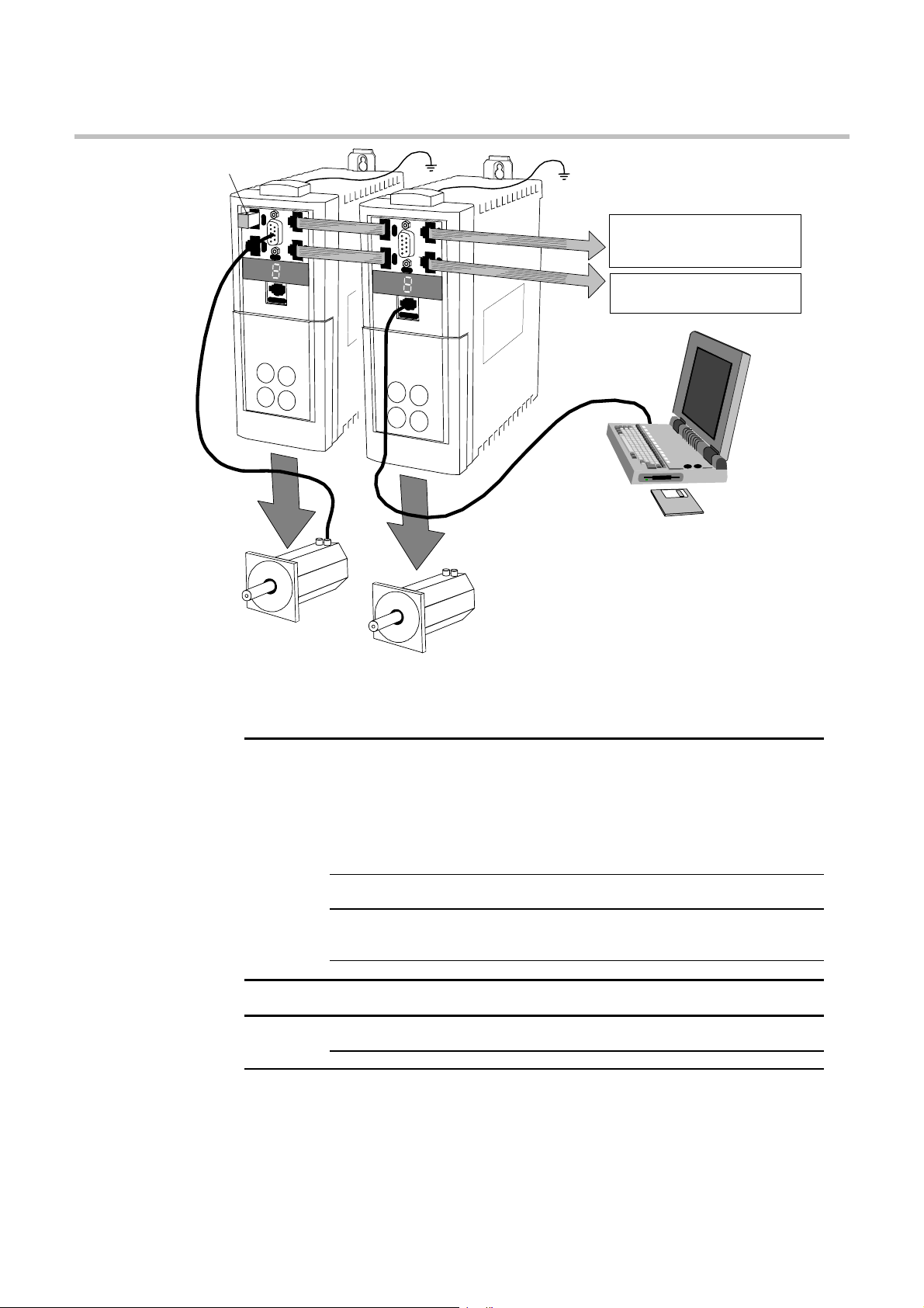
CAN-Bus terminator
X
2
0
X
4
0
X
3
0
X
1
5
/
R
S
2
3
2
Resolver Connection
(mandatory)
POWER
X
2
1
X
4
1
X
X
2
2
0
1
X
4
X
0
4
1
X
3
0
CAN-Bus connection
to next 631 controller
(last controller is terminated)
Encoder/Stepper connection
X
15
/
R
S
2
3
2
POWER
to next 631 controller
EASYRIDER software
used to configure
each 631 individually
Motor 1
Motor 2 (synchronised to Motor 1)
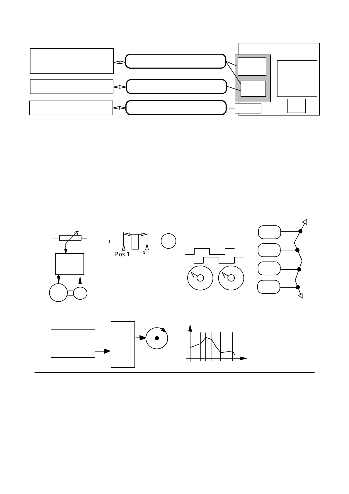
The Servo Drive is controlled via RS232, CAN-Bus or Incremental Bus using a PLC. It is
configured using the EASYRIDER software.
*HQHUDO
*HQHUDO 2SHUDWLQJ#0RGHV 3XOVH2GLUHFWLRQ#,QSXW
*HQHUDO*HQHUDO
“439#YHORFLW\#FRQWURO
7RUXH#FRQWURO
3RVLWLRQ#FRQWURO
(QFRGHU#IROORZHU
0RWLRQ#FRQWURO
%,$6#0#PRWLRQ#ODQJXDJH
&$0#SURILOLQJ
6HWXS/#6HUYLFH/
3URJUDPPLQJ
&RPPXQLFDWLRQV
,QWHUIDFHV
'LDJQRVWLFV 'LDJQRVWLF#IDFLOLW\
3URWHFWLRQ
3URWHFWLRQ 7ULS#&RQGLWLRQV +HDWVLQN#RYHUWHPSHUDWXUH#DQG
3URWHFWLRQ3URWHFWLRQ
)XQFWLRQV 0XOWLSOH#SURWHFWLRQ#IXQFWLRQV#0#UHIHU#WR#&KDSWHU#:
,QSXWV2
,QSXWV2
,QSXWV2,QSXWV2
2XWSXWV
2XWSXWV
2XWSXWV2XWSXWV
,QSXWV “439#+45#ELW,#VHWSRLQW
2XWSXWV 5#2XW=#579#'&
($6<5,'(5#VRIWZDUH
&$10%XV
56565
,QFUHPHQWDO#%XV
7#,Q=#579#'&
Table 2-1 Control Features
964#'LJLWDO#6HUYR#'ULYH
Custom-made Software
=
†
:
PLC
EASYRIDER
?
)
)
'
'
$Q#2YHUYLHZ#RI#WKH#6HUYR#'ULYH##
631 Servo Drive
"
"
_
_
CAN-Bus
X20/X21
RS232
X15
current-loop
speed-loop
position-loop
506
•
†
PLC I/O ±10V
Conventional Control
(analog setpoint value)
+10V -10V
631
)
Instructions
Pos.1
)
Figure 2-2 Communications Options
Point-to-Point
Position Control
'
'
Diagnostics
M
Pos.2
"
Setup
Synchronisation
(electronic gearbox)
X10
_
Programming
CAN-Bus Network
Unit X
Unit Y
631
PLC
CAN
M
Stepper motor
control or
incremental
encoder
R
Pulse Control
631
1 : X
Pos Y
631
AC Servo
Figure 2-3 Typical Applications
CAM Profiling
Pos X
964#'LJLWDO#6HUYR#'ULYH
507##
$Q#2YHUYLHZ#RI#WKH#6HUYR#'ULYH
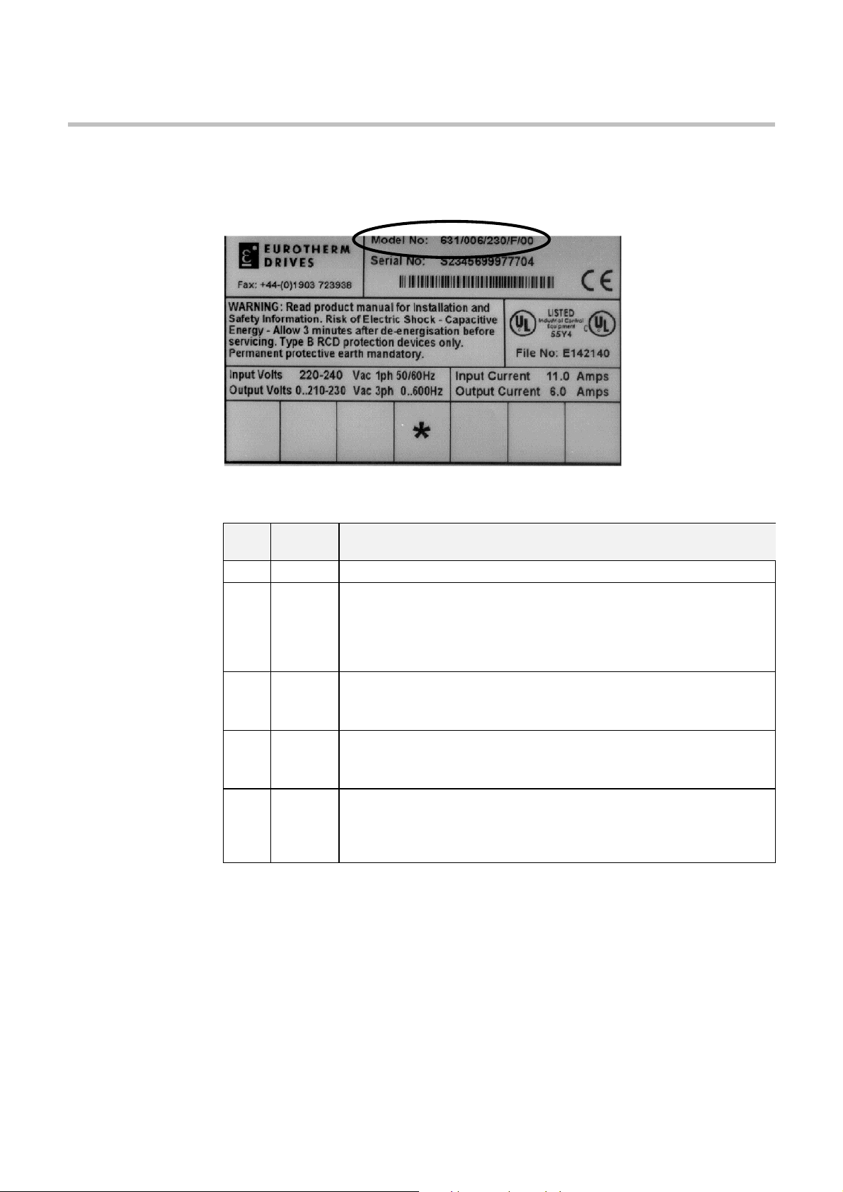
8QGHUVWDQGLQJ#WKH#3URGXFW#&RGH
The unit is fully identified using a five block alphanumeric code which records how the Servo
Drive was calibrated, and its various settings when despatched from the factory.
The Product Code appears as the “Model No.”. Each block of the Product Code is identified as
below:
%ORFN
1R1
([DPSOH
9DULDEOH 'HVFULSWLRQ
4 964 *HQHULF#SURGXFW
5 ;;; 7KUHH#QXPEHUV#VSHFLI\LQJ#WKH#UDWHG#RXWSXW#FXUUHQW
334# #4$
335# #5$
337# #7$
339# #9$
6 ;;; 7KUHH#QXPEHUV#VSHFLI\LQJ#WKH#QRPLQDO#LQSXW#YROWDJH#UDWLQJ=
563 553#WR#5739#+±43(,#83293+]
7 ; 2QH#FKDUDFWHU#VSHFLI\LQJ#WKH#XVH#RI#WKH#,QWHUQDO#(0),#)LOWHU=
)# #)LOWHU
3# #1R#)LOWHU
8 ;; 7ZR#GLJLWV#VSHFLI\LQJ#PHFKDQLFDO#SDFNDJH#LQFOXGLQJ#OLYHU\#DQG#PHFKDQLFDO
SDFNDJH#VW\OH/#DQG#DQ\#RSWLRQ#LQVWDOOHG#RYHU#DQG#DERYH#WKH#VWDQGDUG
IHDWXUHV#RI#WKH#SURGXFW=
33 (XURWKHUP#6WDQGDUG
631/002/230/F/00
Servo Drive Type 631 / rated output current 2A / AC supply 230V / with internal filter /
Eurotherm standard mechanical package.
964#'LJLWDO#6HUYR#'ULYH
6#
167$//,1*#7+(#6(592#
,
'
,QVWDOOLQJ#WKH#6HUYR#'ULYH##
5,9(
604
,03257$17=#
5HDG#&KDSWHU#45=#´&HUWLILFDWLRQ#IRU#WKH#6HUYR#'ULYHµ#EHIRUH#LQVWDOOLQJ#WKLV#XQLW1
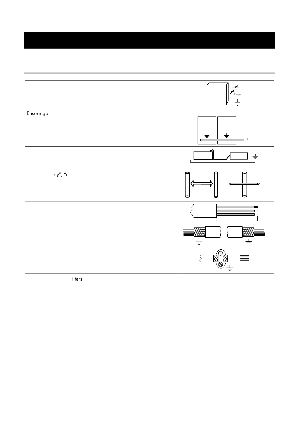
(0&#,QVWDOODWLRQ#+LQWV
$OO#FRPSRQHQWV#DUH#PRXQWHG#RQ#D#PRXQWLQJ#SODWH#+PLQLPXP#WKLFNQHVV
6PP,#LQVLGH#D#VWHHO#FXELFOH1
(QVXUH#JRRG#JURXQGLQJ#RI#WKH#FRPSOHWH#V\VWHP/#LQFOXGLQJ#WKH#JURXQG
FRQQHFWLRQV#EHWZHHQ#WKH#FXELFOH#DQG#PDFKLQH1
,I#PRUH#WKDQ#RQH#PRXQWLQJ#SODWH/#LQWHUFRQQHFW#ZLWK#FRSSHU#UDLOV1
3ODFH#DOO#ZLUHV#DQG#FDEOHV#DV#FORVH#DV#SRVVLEOH#WR#DQ\#JURXQGHG#PHWDO
SODQHV1#3RVLWLRQ#FRQWURO#FDEOHV#FORVH#WR#JURXQGHG#PHWDO#SDUWV#ZKHQ
H[LWLQJ#WKH#FRQWURO#FXELFOH1
6HSDUDWH#´GLUW\µ/#´FOHDQµ#DQG#´VHQVLWLYHµ#FDEOHV#LI#SRVVLEOH#E\#DW#OHDVW
63PP1#&DEOHV#VKRXOG#FURVV#DW#<3ƒ1
$YRLG#FDEOH#ORRSV/#HVSHFLDOO\#EHWZHHQ#WKH#OLQH#ILOWHU#DQG#GULYH#ZKLFK
VKRXOG#EH#DV#FORVH#DQG#DV#VKRUW#DV#SRVVLEOH#+GULOOHG,1
0,3 m
3mm
90°
2QO\#UHPRYH#WKH#UHTXLUHG#OHQJWK#RI#VFUHHQ#IURP#WKH#HQG#RI#WKH#FDEOH1
8 cm max
0DNH#VFUHHQ#FRQQHFWLRQV#DV#DGYLVHG#LQ#WKLV#PDQXDO1#.HHS#VFUHHQHG
FDEOHV#DV#VKRUW#DV#SRVVLEOH/#JURXQG#VFUHHQV#DW#ERWK#HQGV1#)RU#ORQJ
FDEOHV/#PDNH#DGGLWLRQDO#VFUHHQHG#FRQQHFWLRQV#DORQJ#WKH#FDEOH#OHQJWK1
&RQQHFW#VFUHHQV#WR#JRRG#TXDOLW\#JURXQGLQJ#SRLQWV1#8VH#80FOLSV#WR#JLYH
D#693°#FRQQHFWLRQ1
&RQQHFW#DQ\#XQXVHG#ZLUHV#LQ#WKH#FDEOHV#WR#JURXQG1
8VH#RQO\#(XURWKHUP#ILOWHUV#DQG#FDEOHV#IRU#PRWRU#DQG#UHVROYHU1 5HIHU#WR#&KDSWHU#<=#´$FFHVVRULHVµ
964#'LJLWDO#6HUYR#'ULYH
605##
,QVWDOOLQJ#WKH#6HUYR#'ULYH
0HFKDQLFDO#,QVWDOODWLRQ
W
H
H2
D
SIDE VIEW PANEL MOUNTING VIEW DIN MOUNTING VIEW
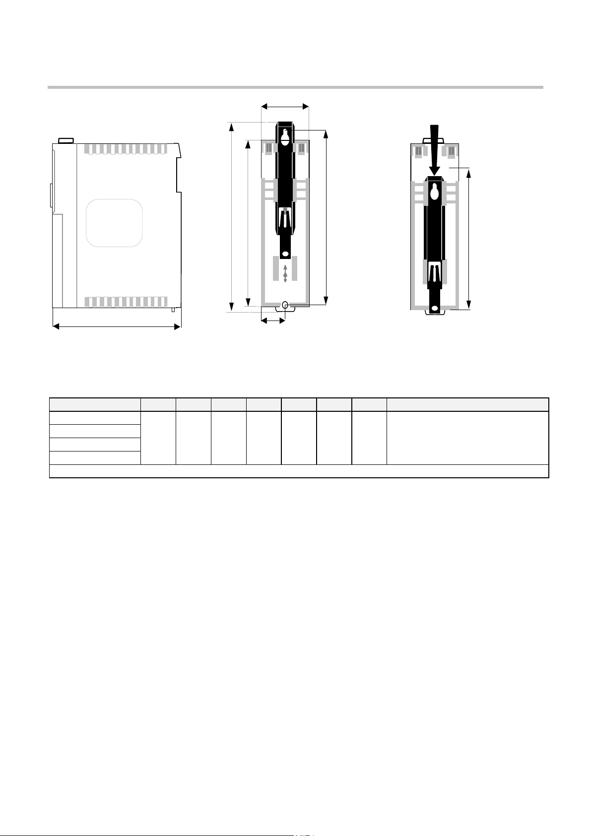
Figure 3-1 Mechanical Dimensions for 631
W1
H1
Adjustable mounting clip can be
easily re-positioned to allow
different mounting configurations
Fixing hole
centres
H3
DIN mounting
dimensions
964#0RGHO#1XPEHU
964#0RGHO#1XPEHU ++++ +4
964#0RGHO#1XPEHU964#0RGHO#1XPEHU
964#2334#25632#1111 0RXQWLQJ#KROHV#818PP
964#23352#5632#1111 4;613 4;;13 53813 48413 :513 6913 4:813 8VH#08#IL[LQJV
964#23372#5632#1111 +:15, +:17, +;14, +81<, +51;, +417, +91<, :HLJKW#418NJ#+616OE,#DSSUR[LPDWHO\
964#23392#5632#1111
1RWH=#
$GGLWLRQDO#VSDFH#LV#UHTXLUHG#WR#WKH#IURQW#RI#WKH#XQLW#IRU#WKH#VLJQDO#PDWLQJ#SOXJV/
+4 +5
+4+4
+5 +6
+5+5
$OO#GLPHQVLRQV#DUH#LQ#PLOOLPHWUHV#+LQFKHV,
+6 :::: :4
+6+6
:4 '''' )L[LQJV
:4:4
)L[LQJV
)L[LQJV)L[LQJV
DSSUR[LPDWHO\#78PP1
0RXQWLQJ#WKH#6HUYR#'ULYH
The unit must be installed in a vertical position to guarantee the best air circulation for the
cooling ribs of the heat sink. Vertical installation above other drive racks or above other heat
producing devices can lead to overheating.
You must install the unit inside a suitable cubicle. The inside of this cubicle must be free from
dust, corrosive fumes, gases, and all liquids including condensation.
If the unit is being installed in a place where condensation is likely, install a suitable
anticondensation heater. The heater must be SWITCHED OFF during normal operation.
Automatic switch off is recommended.
964#'LJLWDO#6HUYR#'ULYH
0LQLPXP#$LU#&OHDUDQFHV
&XELFOH#6L]H
The digital servo drive is protected against damage caused by overheating.
There is a thermal sensor installed on the heat sink. When the temperature rises to >95°C, the
drive is automatically switched off. This setting cannot be changed. Use a cabinet of the correct
size for adequate air circulation, see below.
964#0RGHO#1XPEHU
964#0RGHO#1XPEHU 9ROXPH#RI#&XELFOH
964#0RGHO#1XPEHU964#0RGHO#1XPEHU
964#2334#25632#1111
964#23352#5632#1111
964#23372#5632#1111
964#23392#5632#1111
9HQWLODWLRQ
The servo drive gives off heat in normal operation and must therefore be mounted to allow the
free flow of air through the ventilation slots and heatsink. Maintain minimum clearances for
ventilation as shown below to ensure heat generated by other adjacent equipment is not
transmitted to the Servo Drive. Be aware that other equipment may have its own clearance
requirements. When mounting two or more 631s together, these clearances are additive.
,QVWDOOLQJ#WKH#6HUYR#'ULYH##
9ROXPH#RI#&XELFOH
9ROXPH#RI#&XELFOH9ROXPH#RI#&XELFOH
+PLQLPXP,
+PLQLPXP,
+PLQLPXP,+PLQLPXP,
ó
3145P
606
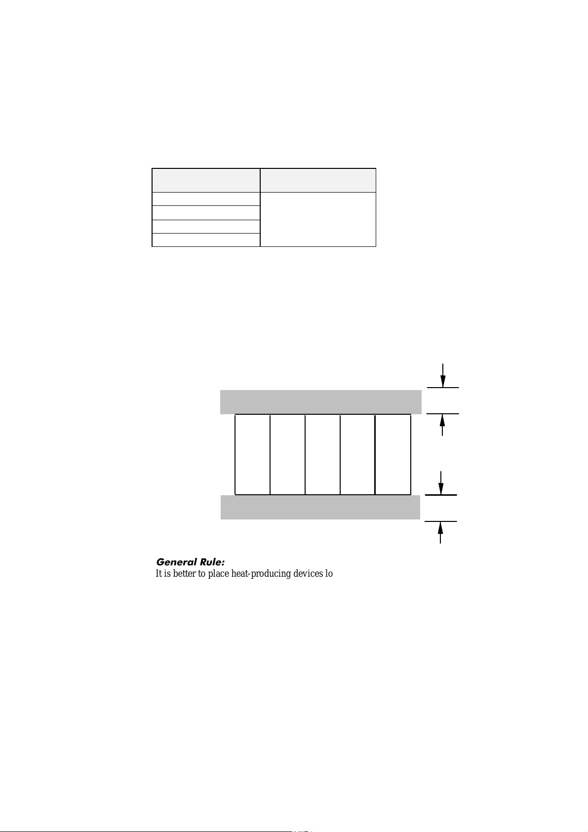
Ensure that the mounting surface is normally cool.
631
631
631
631
631
100mm / 4"
100mm / 4"
*HQHUDO#5XOH=
It is better to place heat-producing devices low down inside an enclosure to support internal
convection, which will spread the heat. If placing devices up high is unavoidable, you should
consider increasing the (upper) dimensions of the cubicle, or installing fans.
964#'LJLWDO#6HUYR#'ULYH
607##
,QVWDOOLQJ#WKH#6HUYR#'ULYH
(OHFWULFDO#,QVWDOODWLRQ
,03257$17=#
1RWH=#
,03257$17=#
3OHDVH#UHDG#WKH#6DIHW\#,QIRUPDWLRQ#RQ#SDJH#&RQW1#6#)#7#EHIRUH#SURFHHGLQJ1
:$51,1*$#
(QVXUH#WKDW#DOO#ZLULQJ#LV#HOHFWULFDOO\#LVRODWHG#DQG#FDQQRW#EH#PDGH#´OLYHµ
XQLQWHQWLRQDOO\#E\#RWKHU#SHUVRQQHO1
$OO#FRQWURO2UHVROYHU2PRWRU#WKHUPLVWRU#LQSXWV/
L1H#SURWHFWHG#E\#GRXEOH#LQVXODWLRQ#DUH#6(/91
'R#QRW#FRQQHFW#WR#QRQ06(/9#FLUFXLWV1
+5HIHU#WR#&KDSWHU#44=#´7HFKQLFDO#6SHFLILFDWLRQVµ#0#,QVXODWLRQ#&RQFHSW,1
5HIHU#WR#&KDSWHU#44=#´7HFKQLFDO#6SHFLILFDWLRQVµ#IRU#DGGLWLRQDO#&DEOLQJ#5HTXLUHPHQWV#DQG
7HUPLQDO#%ORFN#:LUH#6L]HV1
7KH#XVH#RI#YDULDEOH#VSHHG#GULYHV#RI#DOO#NLQGV#FDQ#LQYDOLGDWH#WKH#FHUWLILFDWLRQ#IRU#GDQJHURXV
DUHDV#+DSSDUDWXV#JURXS#DQG2RU#WHPSHUDWXUH#FODVV,#RI#H[SORVLRQ0SURWHFWHG#PRWRUV1
,QVSHFWLRQ#DQG#FHUWLILFDWLRQ#IRU#WKH#FRPSOHWH#LQVWDOODWLRQ#RI#VHUYR#PRWRUV#DQG#HOHFWURQLF
FRPSRQHQWV#PXVW#
PXVW#EH#REWDLQHG1
PXVW#PXVW#
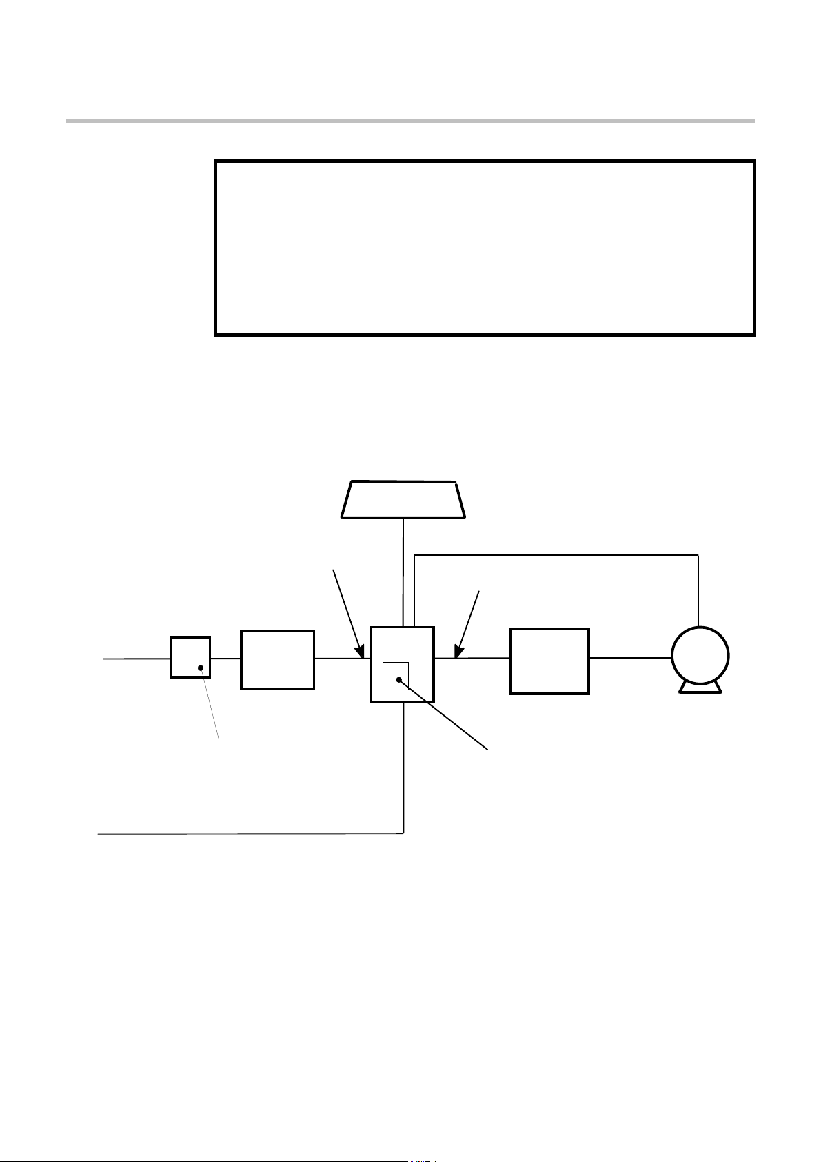
EUDNH#UHVLVWRU
+LI#UHTXLUHG,
+QRLV\,
+QRLV\,
UHVROYHU#FDEOH#+VHQVLWLYH,
+QRLV\,
SRZHU
VXSSO\
FDEOH
+FOHDQ,
IXVH#RU#VXLWDEOH
FLUFXLW#EUHDNHU
+5&'#QRW
VLJQDO2FRQWURO#FDEOH
+VHQVLWLYH,
OLQH
FKRNH
+RSWLRQDO,
UHFRPPHQGHG,
Figure 3-2 Cabling Requirements
Cables are considered to be electrically sensitive, clean or noisy. You should already have
planned your cable routes with respect to segregating these cables for EMC compliance.
If not, refer to Chapter 12: “Certification for the Servo Drive”.
964
PRWRU
FKRNH
+LI#UHTXLUHGO,
LQWHUQDO#DF#VXSSO\#(0&#ILOWHU
+DQ#H[WHUQDO#DF#VXSSO\#(0&#ILOWHU
PXVW#QRW#EH#XVHG#ZLWK#WKH
LQWHUQDO#ILOWHU,
PRWRU
FDEOH
+QRLV\,
PRWRU
964#'LJLWDO#6HUYR#'ULYH
,QVWDOOLQJ#WKH#6HUYR#'ULYH##
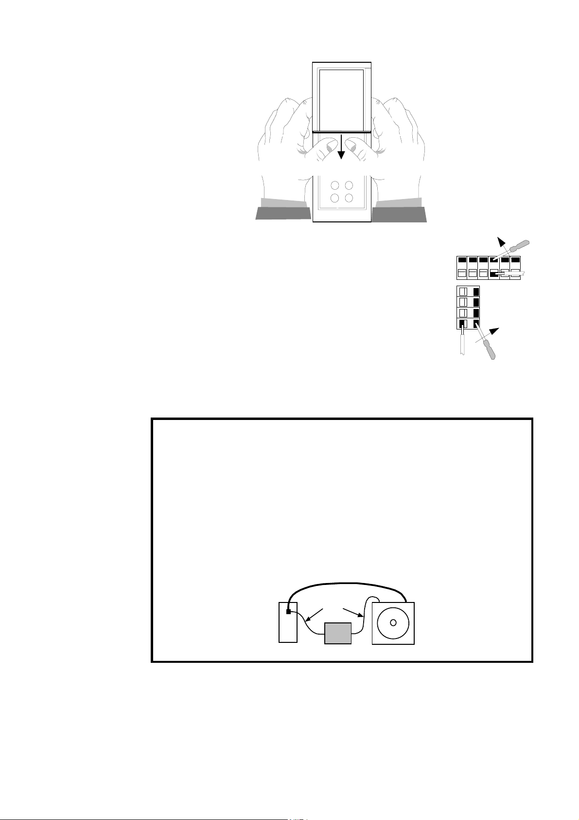
631
Remove Terminal Cover by pressing here and pulling down
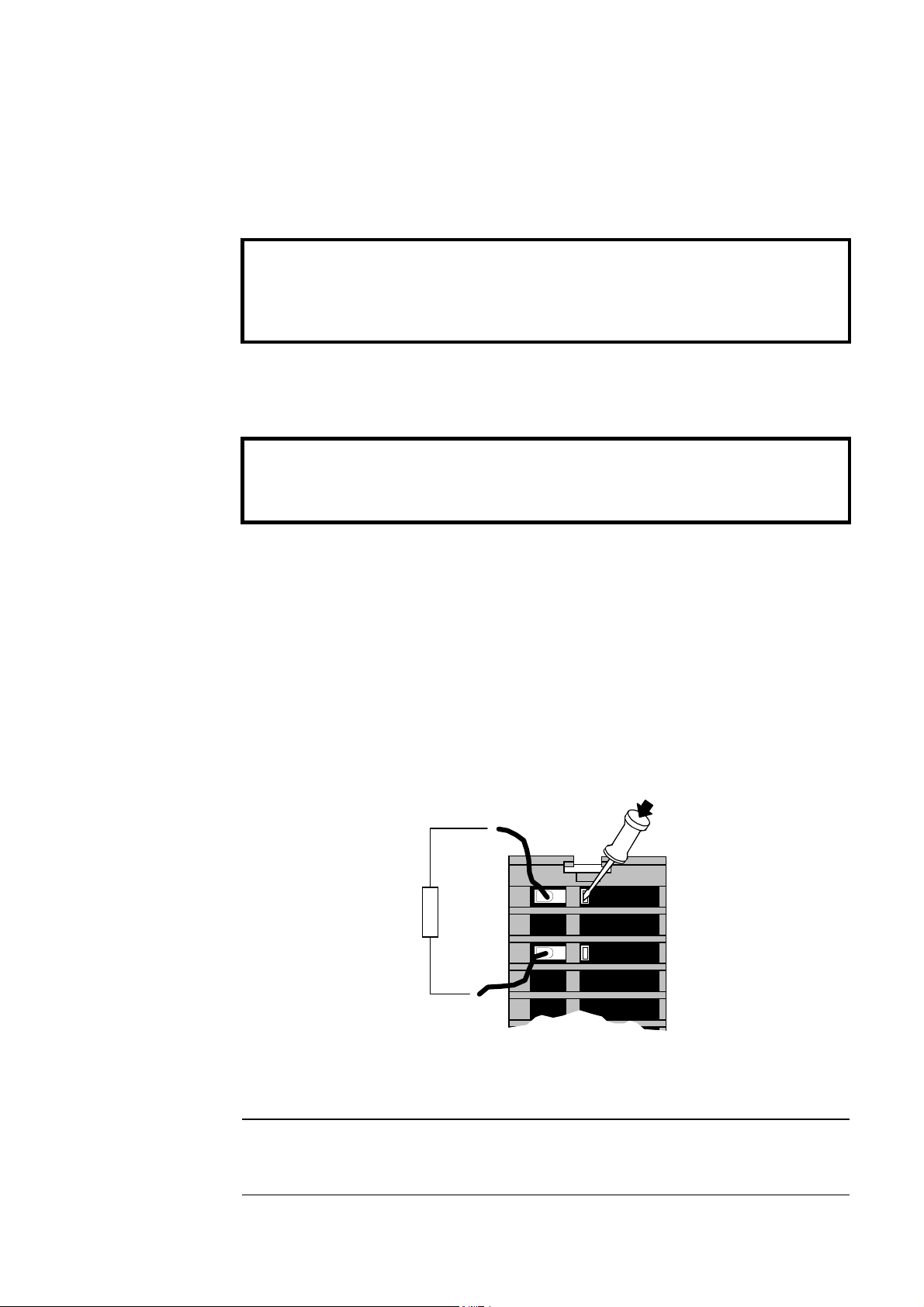
8VLQJ#&DJH#&ODPS#7HUPLQDOV
Remove the terminal cover as shown above.
Insert a flat-bladed screwdriver (size 3.5 mm max.) inside the smallest
hole. Lever the screwdriver, keeping it firmly pressed into the hole. The
cage will open.
Insert the stripped wire (5mm to 6mm/0.22in.) or wire crimp inside the
cage keeping the screwdriver in position.
608
Remove the screwdriver. Note the cage provides the correct force for a
secure
connection.
0RWRU#7KHUPLVWRU
The temperature sensor in the motor windings of the approved Eurotherm servo motors are
classed as SELV, (i.e. protected by double insulation). Refer to Chapter 12: “Certification for the
Servo Drive” - Solid State Motor Overload Protection.
:$51,1*$#
7KH#VHUYR#GULYH#WKHUPLVWRU#FRQQHFWLRQV#DUH#IRU#6(/9#RQO\1
(XURWKHUP#VHUYR#PRWRUV#VHULHV#$&0#5Q/#$&5#Q#DQG#$&*#DUH#6(/9/
RWKHU#PDQXIDFWXUHU·V#PRWRUV#PD\#QRW#EH1
,I#\RX#XVH#D#QRQ0(XURWKHUP#VHUYR#PRWRU/#PDNH#VXUH#WKDW#WKH#WKHUPLVWRU#LV#LQVXODWHG
WR#6(/9#IURP#OLYH#SDUWV#LQVLGH#WKH#PRWRU1#,I#QRW/#WKH#WKHUPLVWRU#VLJQDOV#KDYH#WR#EH#ZLUHG
VHSDUDWHO\#DQG#DQ#DGGLWLRQDO#LVRODWLRQ#FLUFXLW#PXVW#EH#SURYLGHG#EHIRUH#FRQQHFWLQJ#WR
;631
0DNH#VXUH#WKDW#SLQV#5#DQG#9#RI#;63#DUH#RQO\#VHUYHG#E\#6(/9#LQVXODWHG#FDEOH#OHDGV1
resolver cable (without thermistor connections)
thermistor wires
964#'LJLWDO#6HUYR#'ULYH
X30
SELV
631
Isolation
motor
(DUWK#)DXOW#0RQLWRULQJ#6\VWHPV
We do not recommend the use of circuit breakers (e.g. RCD, ELCB, GFCI), but where their use
is mandatory, they should:
• Operate correctly with dc and ac protective earth currents (i.e. type B RCDs as in
Amendment 2 of IEC755).
• Have adjustable trip amplitude and time characteristics to prevent nuisance tripping on
switch-on.
609##
,QVWDOOLQJ#WKH#6HUYR#'ULYH
When the ac supply is switched on, a pulse of current flows to earth to charge the
internal/external ac supply EMC filter’s internal capacitors which are connected between phase
and earth. This has been minimised in Eurotherm Drives’ filters, but may still trip out any circuit
breaker in the earth system. In addition, high frequency and dc components of earth leakage
currents will flow under normal operating conditions. Under certain fault conditions larger dc
protective earth currents may flow. The protective function of some circuit breakers cannot be
guaranteed under such operating conditions.
&LUFXLW#EUHDNHUV#XVHG#ZLWK#96'V#DQG#RWKHU#VLPLODU#HTXLSPHQW#DUH#QRW####VXLWDEOH#IRU
SHUVRQQHO#SURWHFWLRQ1#8VH#DQRWKHU#PHDQV#WR#SURYLGH#SHUVRQDO#VDIHW\1#5HIHU#WR
(1834:;#+4<<;,#2#9'(3493#+4<<7,#2#(19353704#+4<<7,
:LULQJ#WKH#6HUYR#'ULYH
(DUWK#&RQQHFWLRQV
'XH#WR#WKH#ZRUNLQJ#SULQFLSOH#RI#VHUYR#GULYHV#RU#ILOWHUV/#WKHUH#ZLOO#EH#DQ#HDUW#OHDNDJH
:$51,1*$#
:$51,1*$#
FXUUHQW#H[FHHGLQJ#43P$#GF/#618P$#DF1
,03257$17=#
5HIHU#WR#´(DUWK#)DXOW#0RQLWRULQJ#6\VWHPVµ1#SDJH#6081
The wiring terminals accept a maximum conductor size of 12 AWG (3.2mm²).
The servo drive, when fitted with an internal ac supply EMC filter, is only suitable for earth
referenced supplies (TN).
Refer to Chapter 12: “Certification for the Servo Drive” for information on earthing
requirements.
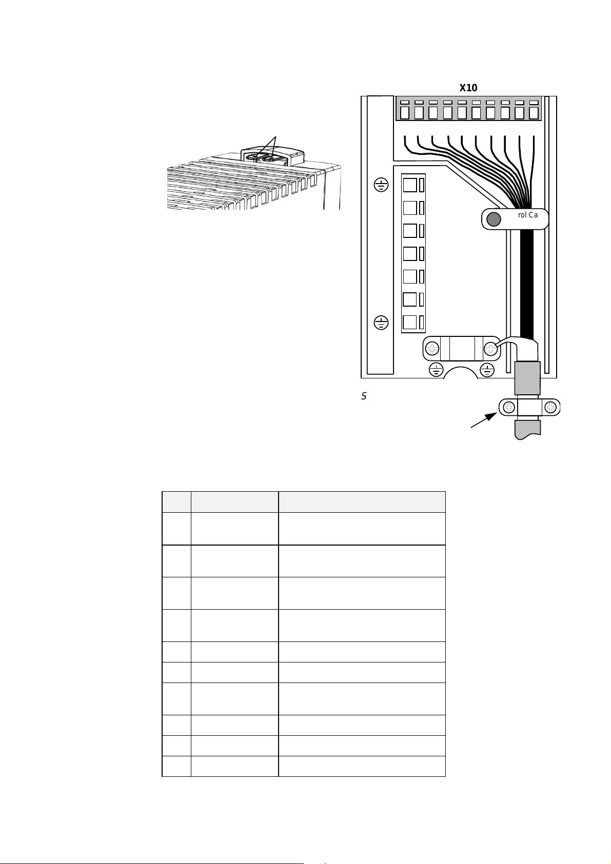
'%54#)#'%55#0#([WHUQDO#%UDNH#5HVLVWRU
Refer to Chapter 14: “Application Notes” - Dynamic Braking for selection details and Chapter
11: “Technical Specifications” - Power Details.
DBR1
DBR2
Top View of 631
Figure 3-3 External Brake Resistor Terminals
&DXWLRQ#
7KH#UHVLVWRU#VKRXOG#EH#PRXQWHG#RQ#D#KHDWVLQN#+EDFN#SDQHO,#DQG#FRYHUHG#WR#SUHYHQW#LQMXU\
IURP#EXUQLQJ1
964#'LJLWDO#6HUYR#'ULYH
,QVWDOOLQJ#WKH#6HUYR#'ULYH##
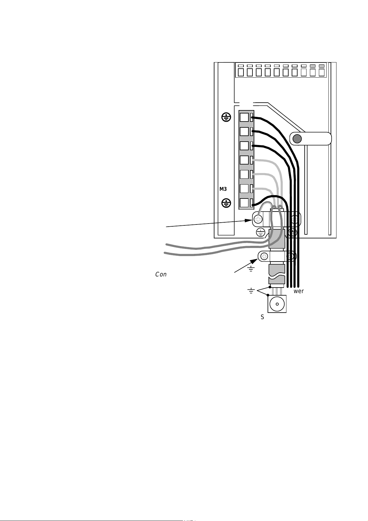
0RWRU#DQG#3RZHU#:LULQJ#&RQQHFWLRQV#+;4,
123456 78910
X1
protective earth
60:
Motor Cable Clamp
To Motor Brake
control circuitry
Screen Connections - ensure good
connection with conductive surface
on the cubicle, remove varnish.
230V ac 50/60Hz supply
230V ac 50/60Hz supply
motor supply
motor supply
motor supply
protective earth
red
blue
L1
L2/N
M1/U
M2/V
M3/W
Power
1RWH=#
Servo Motor
Figure 3-4 631 Power and Earth Wiring Connections
7KH#XQLW#PXVW#EH#SHUPDQHQWO\#HDUWKHG#XVLQJ#WZR#LQGHSHQGHQW#HDUWK#FRQGXFWRUV#XVLQJ#;41
3URWHFW#WKH#LQFRPLQJ#PDLQV#VXSSO\#XVLQJ#D#VXLWDEOH#IXVH#RU#FLUFXLW#EUHDNHU#DV#VKRZQ#LQ
&KDSWHU#44=#´7HFKQLFDO#6SHFLILFDWLRQVµ#0#3RZHU#'HWDLOV1
0RWRU#&DEOH#&ODPS
In order to conform with the specified generic EMC standards, the motor cable must be screened
and the screen connected to both the motor frame and the motor cable clamp. This clamp is
internally connected to power terminals PE (Protective Earth) and provides convenient 360°
connection. It is used for the motor protective earth, motor and control cable screen connections.
Refer to Chapter 12: “Certification for the Servo Drive” for information on meeting generic
EMC standards and minimising electrical interference.
964#'LJLWDO#6HUYR#'ULYH
60;##
,QVWDOOLQJ#WKH#6HUYR#'ULYH
&RQWURO#:LULQJ#&RQQHFWLRQV#+;43,
Functional Earth connected to
cubicle backplate providing clean earth
for electronic ground and screens
X10
123456 78910
Figure 3-5 631 Control Wiring Connections
Pin Type Function
L1
L2/N
M1/U
M2/V
M3/W
Screen Connections:
ensure good connection
with conductive surface
on the cubicle.
Remove varnish.
Control Cable
Retainer
Control
1
±10V, Ri - 10k
2
±10V, Ri - 10k
3 0V PLC External supply for digital i/o,
4 24V DC PLC External supply for digital i/o,
5 Opto-OUT Configurable ? (s. 3.1.1)
6 Opto-OUT Configurable ? (s. 3.1.1)
7 Opto-IN ACTIVE, non-configurable
8 Opto-IN Configurable ? (s. 3.1.1)
9 Opto-IN Configurable ? (s. 3.1.1)
10 Opto-IN Configurable ? (s. 3.1.1)
ANALOG IN, differential to pin 2
Ω
referenced to GND
ANALOG IN, differential to pin 1
Ω
referenced to GND
related to pin 4
related to pin 3
activates motor power when high
964#'LJLWDO#6HUYR#'ULYH
,QVWDOOLQJ#WKH#6HUYR#'ULYH##
60<
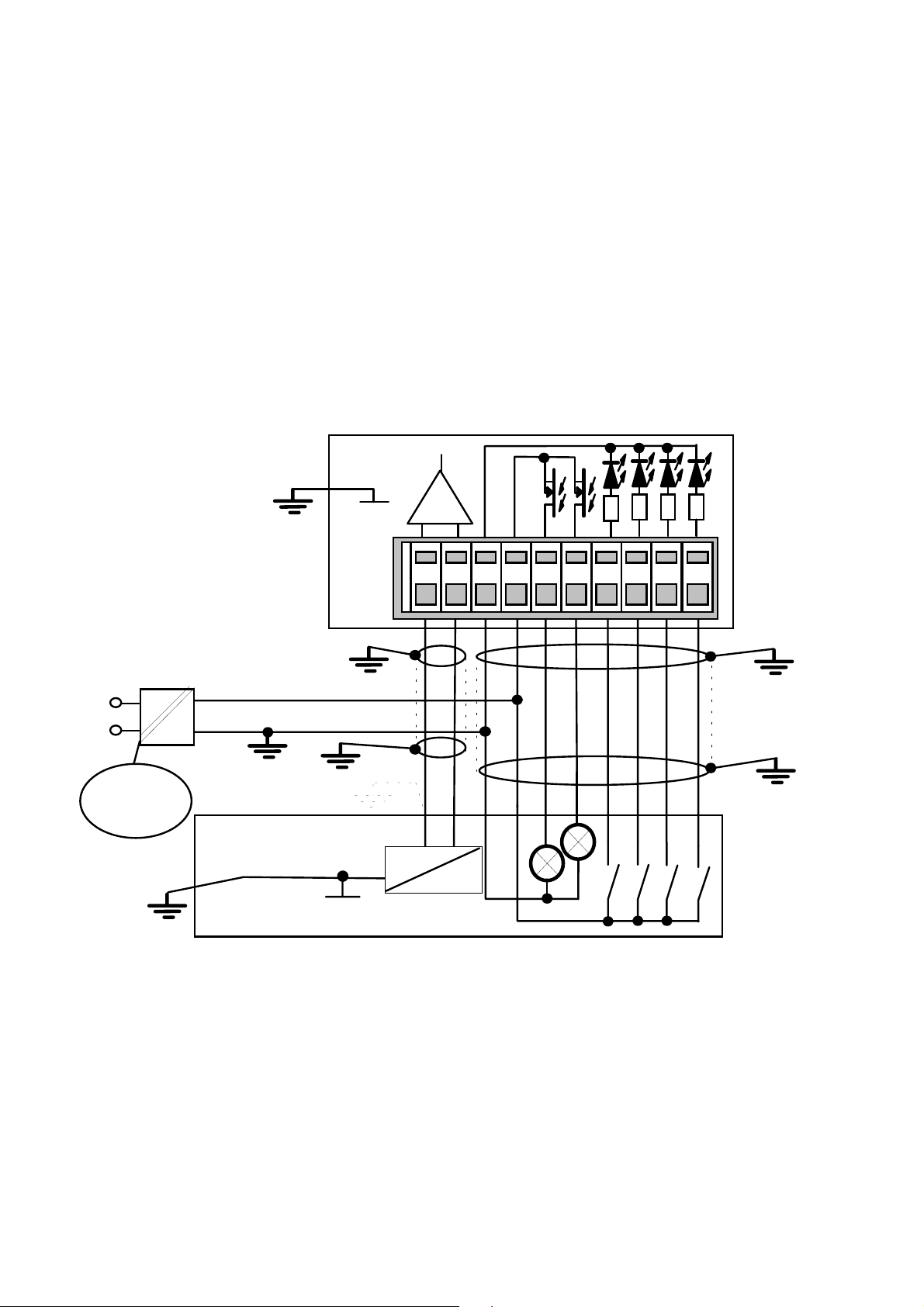
1RWH=#
8VH#VFUHHQHG#FRQWURO#FDEOHV#WR#FRPSO\#ZLWK#(0&#UHTXLUHPHQWV1
All control and signal terminals are SELV, i.e., protected by double/re-inforced insulation.
Ensure all wiring is rated for the highest system voltage. Control wiring of between 0.08 mm
(28 AWG) - 2.5 mm2 (14 AWG) can be used.
&RQWURO#&DEOH#5HWDLQHU
This clip is used to provide guaranteed segregation of the control and power cables. It may be
reotated in either direction to allow easy installation of the control cables.
Refer to Chapter 4: “Operating the Servo Drive” - Operating Modes.
Refer to Chapter 11: “Technical Specifications” for Control Terminal information.
Refer to Chapter 12: “Certification for the Servo Drive” for information on meeting generic
EMC standards and minimising electrical interference.
1
0V
23
I/O Functions
according to
set-up with
EASYRIDER
4
6
5
8
7
9
10
?
631
X10
2
I/O supply
to be installed by User
L1
N
SELV Isolation
~
=
DC +24V PLC
0V PLC
*
PLC
Analog
Digital
Functions according to user-software
Analog Output. Polarity according to requirement. Setpoint output and input are working related to earth.
*
It may be useful to connect one pole directly to earth, refer to PLC information.
Figure 3-6 Typical Connection to the Control Terminals (X10)
964#'LJLWDO#6HUYR#'ULYH
6043##
,03257$17=#
motor end controller end (X30)
,QVWDOOLQJ#WKH#6HUYR#'ULYH
5HVROYHU#&RQQHFWLRQ#+;63,
5HIHU#WR#WKH#:$51,1*#RQ#SDJH#6081
The resolver provides a digital value for the rotor position to within one revolution, evaluation:
12 or 14 bit. It is adjustable in the Configuration Menu in the EASYRIDER software.
• commutation according to pole pair number
• actual speed value
• incremental position output
• position value for position regulation
The supplied resolver cable is plugged in to the front of the 631 (socket X30), and into the
socket on the Eurotherm approved servo motor. This connection must be made for the 631 to
control the operation of the motor. The cable contains wiring for the resolver and the motor
thermistor.
front
front
891
7
12
6
54
1
2
10
3
4
11
11
2
10
8
9
12
5
solder side
3
7
6
1RWH=#
Pin No.
1
2
3
4
8
7
5
6
9
10
11
12
FunctionColour
white
brown
green
yellow
grey
pink
red
blue
sin +
sin cos +
cos -
carrier +
carrier PTC optional
PTC optional *
screen
screens can be connected to ground
with U-clip or gland using 360°connection
Pin No.
4
8
3
7
5
9
2
6
1
2
3
4
5
solder side
Figure 3-7 Resolver Connections (as supplied cable model KIR)
7KH#SOXJ#W\SH#VKRZQ#DERYH#LV#IRU#XVH#ZLWK#(XURWKHUP#PRWRU#W\SHV#$&0#5Q/#$&5#Q#DQG
$&*#RQO\1
1
6
2
7
3
8
4
9
5
1
6
7
8
9
964#'LJLWDO#6HUYR#'ULYH

,QVWDOOLQJ#WKH#6HUYR#'ULYH##
6044
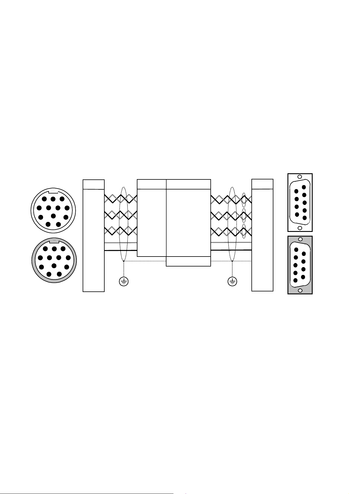
0XOWL0IXQFWLRQ#,QSXW22XWSXW#&RQQHFWLRQV#+;732;74,
This connection provides encoder emulation, encoder input and stepper motor interface.
1RWH=#
5HIHU#WR#&KDSWHU#44=#´7HFKQLFDO#6SHFLILFDWLRQVµ#0#;732;74#0#0XOWL0IXQFWLRQ#,QSXW22XWSXW1
GND
X40 X41
Incremental-Out
MASTER
631
mount units side-by-side if possible
keep cables as short as possible
X40/41 signals are referred to PE
Figure 3-8 Application Example
To synchronise several 631 servo drives, connect the X40/41 sockets as shown using the
specified cables. The 631 is configured using EASYRIDER software
GND
X40 X41 X40 X41
Incremental-IN
SLAVE 1
631 631
GND
Incremental-IN
SLAVE 2
.
?
The X40/X41 input/output functions are configurable using the EASYRIDER ?#software.
Functions:
Mode 0 Incremental Output
Mode 1 Incremental Input
Mode 2 Step Control Pulse/Direction
Mode 3 Step Control Pulse (+) ( -)
964#'LJLWDO#6HUYR#'ULYH
6045##
,QVWDOOLQJ#WKH#6HUYR#'ULYH
#0RGH#3#0#,QFUHPHQWDO#2XWSXW#+;732;74,
•
Incremental encoder simulation for processing in positioning modules
•
Standard: 1024 increments; other selectable pulse numbers are 512, 256, 128
GND
A
/A
B
/B
Z
/Z
Incremental Encoder inputs or outputs
;73
;73 3LQ
;73;73
3LQ )XQFWLRQ
3LQ3LQ
;0SROH#0RGXODU#-DFN/
VFUHHQHG
GND
1
8
/Z
Z
/B
B
/A
A
5VI
PLC
IN
X40
Encoder Emulation,
based on Resolver
conversion
)XQFWLRQ ;74
)XQFWLRQ)XQFWLRQ
Incremental OUT
;74
;74;74
($6<5,'(5#?#;73##PRGH# #3 ;0SROH#0RGXODU#-DFN/
VFUHHQHG
;73#DQG#;74#DUH#LGHQWLFDO#DQG#LQWHUQDOO\#VZLWFKHG
LQ#SDUDOOHO1
1
+;73# #;74,#WKHUHIRUH#ZLULQJ#LV#YHU\#HDV\1
8
LQWHUQDO#FRQQHFWLRQ#WR
&DVH=#6FUHHQHG
*1'
4444 *1'
5555 LQYHUWHG#30,QGH[ 287##2=
666630,QGH[ 287##=
7777 &KDQQHO#%#LQYHUWHG 287##2%
8888 &KDQQHO#% 287##%
9999 &KDQQHO#$#LQYHUWHG 287##2$
:::: &KDQQHO#$ 287##$
;;;; 2XWSXW#VXSSO\#YROWDJH
89,
8189#GF#PD[1#483P$
X41
631
GND
/Z
Z
/B
B
/A
A
5VI
'HVLJQ#5XOH
The capability of input frequency of any connected device must at least meet the selected value
of pulse outputs (increments) on X40.
n = maximum speed (rpm)
x = increments e.g. 1024
f = output frequency at X40/41 4,5,6,7
n * x
Formula:
f=
Example: n = 4000 rpm
50
=[Hz]
f=
4000 * 1024
50
= 81920 Hz
964#'LJLWDO#6HUYR#'ULYH
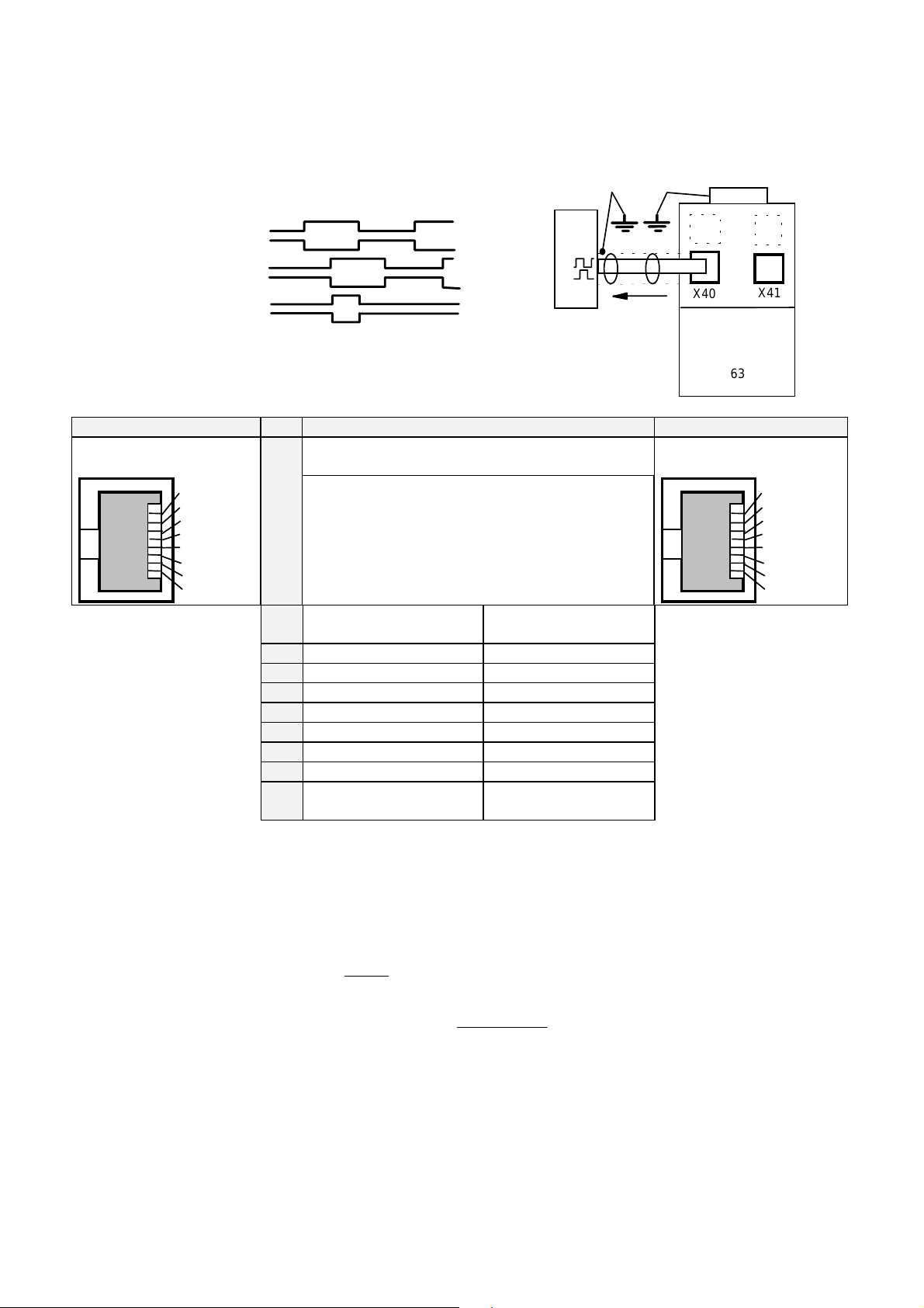
#0RGH#40#,QFUHPHQWDO#,QSXW#+;732;74,
Parameter area of the input signals is 10 - 1,000,000 increments
A
/A
B
/B
Z
/Z
Incremental Encoder inputs or outputs
;73
;73 3LQ
;73;73
;0SROH#0RGXODU#-DFN/
VFUHHQHG
3LQ )XQFWLRQ
3LQ3LQ
,QVWDOOLQJ#WKH#6HUYR#'ULYH##
Encoder IN
Encoder
)XQFWLRQ ;74
)XQFWLRQ)XQFWLRQ
;74
;74;74
X40 X41
Mode = 1
Incremental IN
6046
GND
631
($6<5,'(5#?#;73##PRGH# #4 ;0SROH#0RGXODU#-DFN/
VFUHHQHG
GND
1
8
/Z
Z
/B
B
/A
A
5VI
;73#DQG#;74#DUH#LGHQWLFDO#DQG#LQWHUQDOO\#VZLWFKHG
LQ#SDUDOOHO1
+;73# #;74,#WKHUHIRUH#ZLULQJ#LV#YHU\#HDV\1
LQWHUQDO#FRQQHFWLRQ#WR
&DVH=#6FUHHQHG
1
8
GND
/Z
Z
/B
B
/A
A
5VI
*1'
4444 *1'
5555 LQYHUWHG#30,QGH[ 287##2=
666630,QGH[ 287##=
7777 &KDQQHO#%#LQYHUWHG 287##2%
8888 &KDQQHO#% 287##%
9999 &KDQQHO#$#LQYHUWHG 287##2$
:::: &KDQQHO#$ 287##$
;;;; 2XWSXW#VXSSO\#YROWDJH
89,
8189#GF#PD[1#483P$
1RWH=#
7KH#RSHUDWLRQ#RI#LQFUHPHQWDO#HQFRGHUV#ZKHQ#XVLQJ#ORQJ#FDEOHV#PD\#FDXVH#D#YROWDJH#GURS
RI#WKH#HQFRGHU#SRZHU#VXSSO\1#:H#VXJJHVW#XVLQJ#DQ#H[WHUQDO#VXSSO\#LI#QHFHVVDU\1
964#'LJLWDO#6HUYR#'ULYH
6047##
Pulse
Direction
,QVWDOOLQJ#WKH#6HUYR#'ULYH
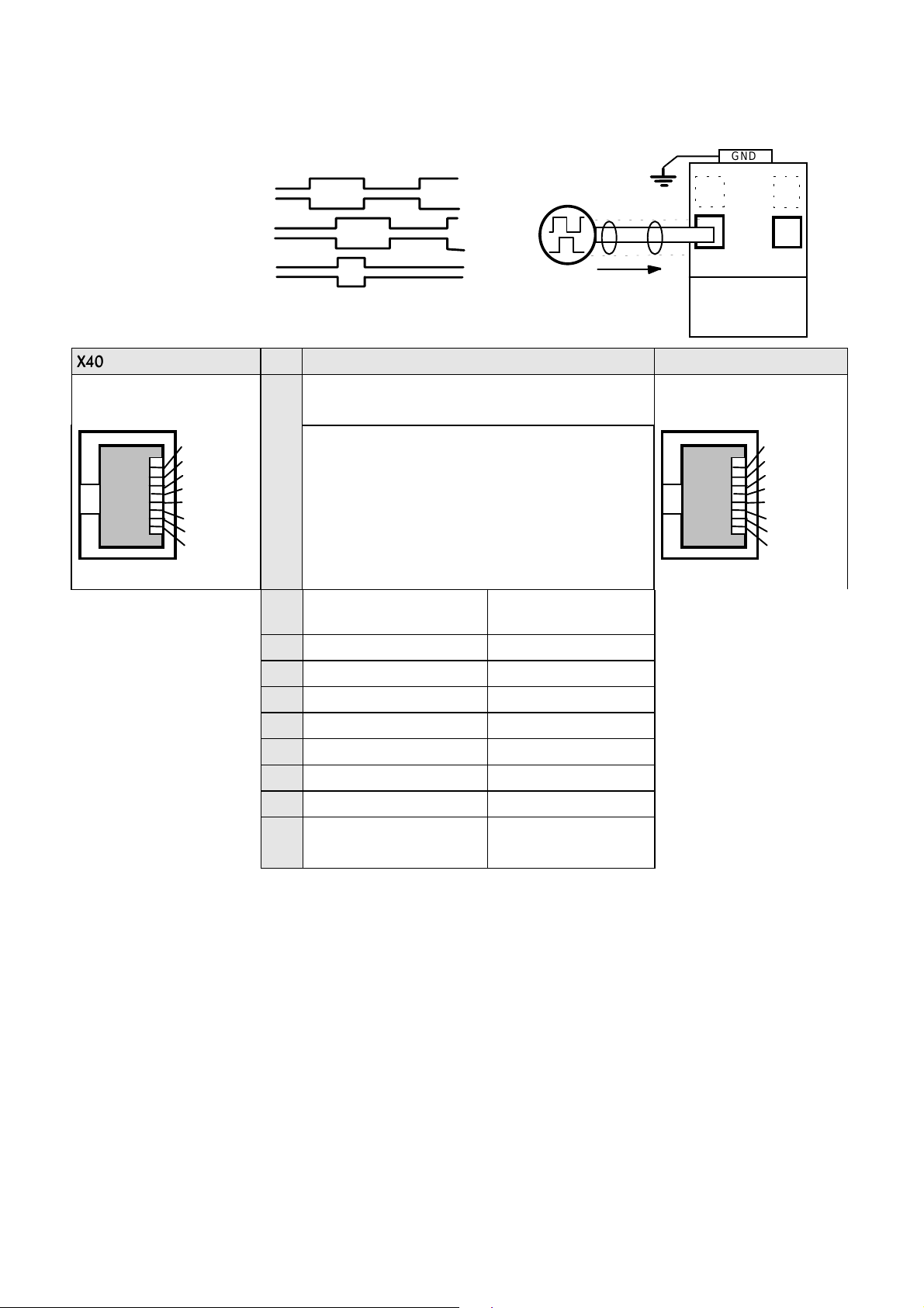
#0RGH#5#0#6WHS0&RQWURO#3XOVH2'LUHFWLRQ#+;732;74,
1
1
set-up time
turn direction (-)
2.5µs
2
2
hold time = 0
turn direction (+)
Stepper
Motor
Control
GND
631
X40
Steps in
Pulse/Direction
Mode = 2
X41
;73
;73 3LQ
;73;73
3LQ )XQFWLRQ
3LQ3LQ
;0SROH#0RGXODU#-DFN/
VFUHHQHG
GND
1
8
/Z
Z
/B
B
/A
A
5VI
)XQFWLRQ
)XQFWLRQ)XQFWLRQ
($6<5,'(5#?#;73##PRGH# #5
;73#DQG#;74#DUH#LGHQWLFDO#DQG#LQWHUQDOO\#VZLWFKHG
LQ#SDUDOOHO1
+;73# #;74,#WKHUHIRUH#ZLULQJ#LV#YHU\#HDV\1
LQWHUQDO#FRQQHFWLRQ#WR
&DVH=#6FUHHQHG
*1'
4444 *1'
5555 'LUHFWLRQ#LQYHUWHG ,1#25
6666 'LUHFWLRQ ,1#5
7777 'ULYH#$FWLYH 2XW#5HDG\
8888 'ULYH#$FWLYH#LQYHUWHG 2XW#25HDG\
9999 3XOVH 287##2$
:::: &KDQQHO#$,1#3
;;;; 2XWSXW#VXSSO\#YROWDJH
89,
8189#GF#PD[1#483P$
;74
;0SROH#0RGXODU#-DFN/
VFUHHQHG
GND
1
8
/Z
Z
/B
B
/A
A
5VI
964#'LJLWDO#6HUYR#'ULYH
pulse direction (+)
)
pulse direction (-
,QVWDOOLQJ#WKH#6HUYR#'ULYH##
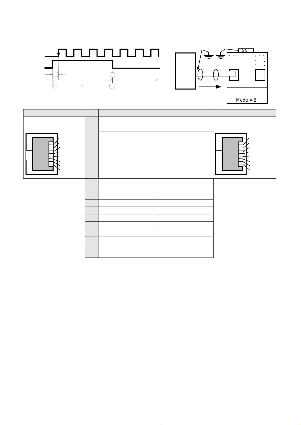
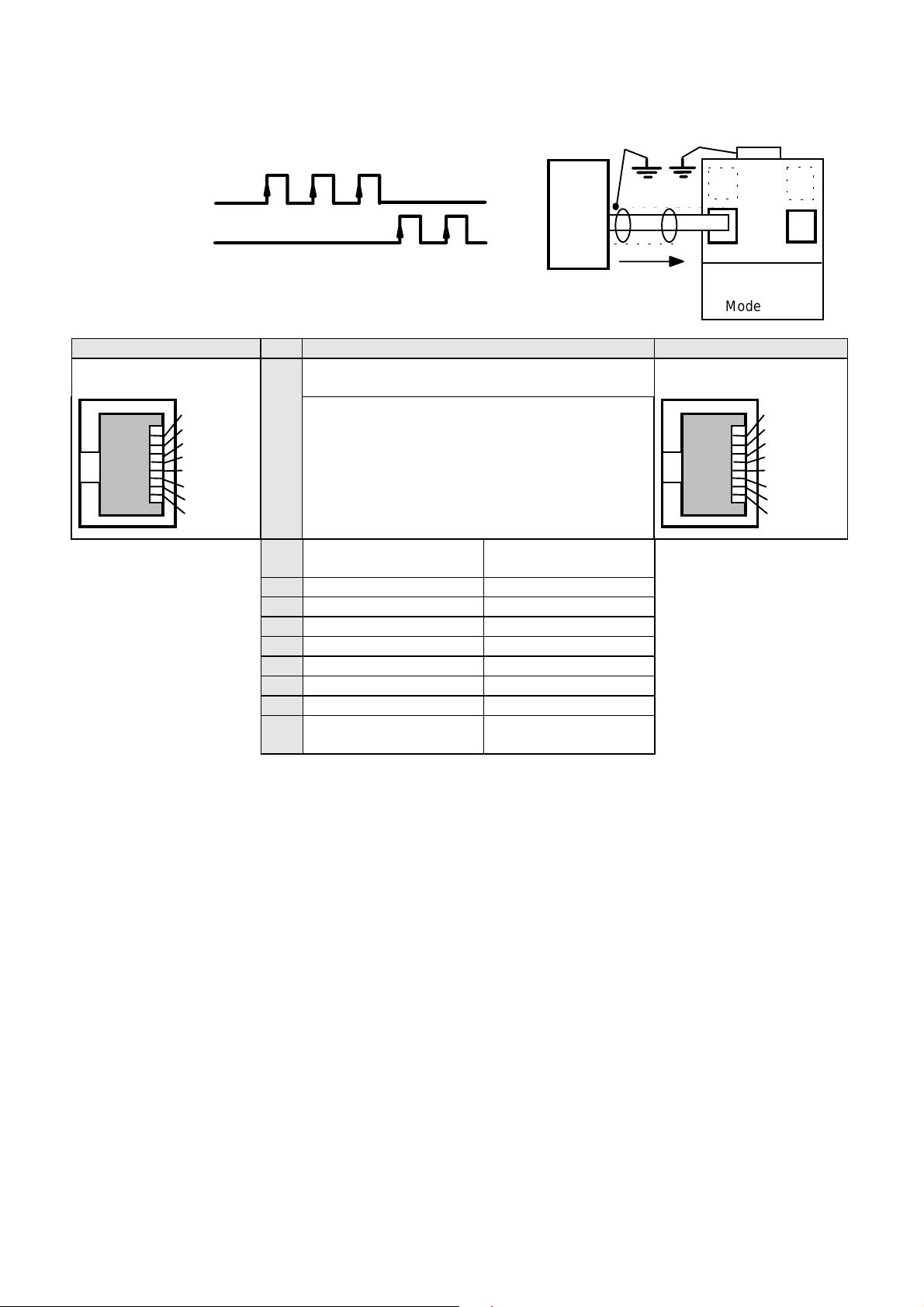
#0RGH#6#0#6WHS#&RQWURO#3XOVH#+.20,##+;732;74,
Stepper
Motor
Control
GND
631
X40
Steps In
Pulse (+) (-)
Mode = 3
6048
X41
;73
;0SROH#0RGXODU#-DFN/
VFUHHQHG
GND
1
8
/Z
Z
/B
B
/A
A
5VI
)XQFWLRQ ;74
3LQ
3LQ
3LQ3LQ
($6<5,'(5#?#;73##PRGH# #6 ;0SROH#0RGXODU#-DFN/
VFUHHQHG
;73#DQG#;74#DUH#LGHQWLFDO#DQG#LQWHUQDOO\#VZLWFKHG
LQ#SDUDOOHO1
+;73# #;74,#WKHUHIRUH#ZLULQJ#LV#YHU\#HDV\1
LQWHUQDO#FRQQHFWLRQ#WR
&DVH=#6FUHHQHG
*1'
1
*1'
2
3XOVH#+.,#,QYHUWHG ,1#23.
3
3XOVH#+., ,1#3
4
'ULYH#$FWLYH 2XW#5HDG\
5
'ULYH#$FWLYH#LQYHUWHG 2XW#25HDG\
6
3XOVH#+0, ,1#30
7
3XOVH#+0,#LQYHUWHG ,1#230
8
2XWSXW#VXSSO\#YROWDJH
89,
8189#GF#PD[1#483P$
GND
1
8
/Z
Z
/B
B
/A
A
5VI
964#'LJLWDO#6HUYR#'ULYH
 Loading...