

Page 1

WV418-2000
ULTRA SLIMPAK® II
WV418
DC Powered RTD Input
Isolating Signal Conditioner
High Accuracy Signal Conditioner with an
Isolated DC Voltage or Current Output
Lower Power Requirements with SmartPower
Improved Accuracy
Bussed Power with Plug-in Power Clips
Removable Terminals for Easy Service
Description
The Ultra SlimPak II is an exciting new line of isolating signal
conditioners from Action Instruments with greater accuracy and
better stability than virtually any other signal conditioners on the
market today. The Ultra SlimPak II features Smart Power, which
eliminates wasted power for low loop resistance loads in the
current output mode.
The WV418 supports 2-wire, 3-wire or 4-wire Pt100 RTDs with
alphas of either 0.00385 or 0.00392, as well as Cu10. Ranges are
DIP switch selectable or (optionally) PC programmable. Outputs
include 0-10V, 0-20mA and 4-20mA.
Smart Power
The Ultra SlimPak II uses Smart Power to control its output supply.
Smart Power automatically adjusts the the voltage to drive the
output loop to the required current. A low impedance current
loop will subsequently require less voltage than a loop with higher
impedance. Previous designs provided only a single supply at the
highest voltage required to drive the highest impedance load.
Using Smart Power results in power savings and reduces the
operating temperature of the signal conditioner.
RoHS Compliant
Touch Cal for Best Stability and Accuracy
DIP Switch Configuration
Supports 2, 3 or 4 Wire RTD's
Enhanced LED Diagnostics
Other than when executing the pushbutton calibration routine,
the LEDs blink under the following conditions:
GREEN:
Flashes at 2Hz when the input is under range.
Flashes at 8Hz when the input is over range.
RED:
Flashes at 2Hz when the output is under range.
Flashes at8Hz when the output is over range.
An Under Range condition exists when the signal is lower than the
operational low value minus 6.25% of the operational span. An
Over Range condition exists when the signal is higher than the
operational high value plus 6.25% of the operational span.
A voltage output short circuit may cause an under range condition
(RED blinking at 2Hz rate). A current output open circuit may cause
an over range condition (RED blinking at an 8Hz rate).
There could be two or more LEDs blinking at the same time, which
means the module has more than one error condition. Only when
all error conditions have been removed will the LEDs be back to
normal (Green ON, Red and Yellow Off).
Page 2
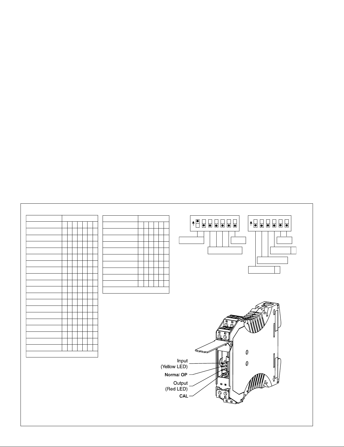
Configuring Modules
Unless otherwise specified, the factory presets the Model WV418
as follows:
Input: Pt100, 3-wire, alpha = 0.00385
Range: -200 to 600°C
Output: 4-20mA
Reverse Out: Off
Remote Cal: Off
1. For other ranges, refer to the SWITCH SETTINGS table.
Reconfigure switches S1 and S2 for the desired input type and range.
Calibration
See the calibration flowchart in Figure 3. The complete calibration
procedure is contained in the Installation & Calibration Instructions document, which is available on our website
(www.actionio.com). You can also obtain it by telephoning Action
technical support (
Note that Custom Calibration (option C620) is available from the
factory (settings MUST be within the units specifications). For a
C620, specify the following:
a) Input Type, Range and Units.
2. Set position 1 of S2 to ON if a WVC16 will be utilized and remote
calibration capability is desired.
3. Set position 2 and 3 of S2 for the desired output type and range.
4. Set position 4 of S2 to ON for reverse output operation.
5. Set positions 1-7 of S1 and positions 5 & 6 of S2 for the desirred
input range.
It is also possible to remotely select the setpoints using an Ethernet
connection and the optional WVC16 WebView Communications
Interface module.
ahplaDTR
:yeK a/n=-;desolCroNO=1=
noitcnuF1S
123 45 67
egnaRtupnI001tP
C006ot002--- -
C062ot002----
C001-ot002---
C001ot05----
C003ot81---
egnaRtupnI01uC
C062ot002----
C001ot002----
C001-ot002---
C001ot05----
C062ot81---
noitarugifnoCDTR
eriW4-----
eriW3
-----
eriW2
-----
58300.0tP------
29300.0tP------
-
-
-
-
:yeK a/n=-;desolCroNO=1=
noitcnuF2S
123 45 6
epyTDTR
001tP---
01uC---
tuptuOesreveR
laCetomeR
-----
egnaRtuptuO
V01ot0----
Am02ot0----
Am02ot4----
ON = Closed
1
RTD Config: 3-wire
(see Table)
b) Output Type, Range and Units.
c) Reverse Output (ON/OFF)
ON = Closed
3
2
Input: -200 to 600°C
45
(see Table)
6
RTD Alpha:
7
0.00385
1
2
Output Range: 4-20mA
Remote Cal Enable
Remote Cal DisableOnOff
Default Switch Settings
45
3
Reverse Output
Direct outputOnOff
(see Table)
RTD Type:
Pt100
6
Figure 1: Switch Settings
Page 3

53 Sense
(4-wire only)
41 RTD +
42 RTD -
43 RTD Return
niPnoitpircseD
11 )+(rewoPCD
21 )-(rewoPCD
31 noitcennoCoN
12 )+(rewoPCD
22 )-(rewoPCD
32 noitcennoCoN
14 )+(tupnIDTR
24 )-(tupnIDTR
34 nruteRDTR
15 )+(tuptuO
25 )-(tuptuO
35 )+(esneSDTR
Figure 2: Wiring Connections
Figure 3: Calibration Flowchart
Page 4

Specifications
r
Inputs:
Sensor Types:
Pt100, 0.00385 alpha & 0.00392 alpha
Cu10
Sensor Connection: 2-wire, 3-wire or 4-wire RTD
Ranges:
Pt100 RTDs:
Range
Number
°C °F alpha
-200 to 600 -328 to 1112 0.00385 1
-200 to 260 -328 to 500 0.00385 2
-200 to -100 -328 to -148 0.00385 3
-50 to 100 -58 to 212 0.00385 4
-18 to 300 0 to 572 0.00385 5
-200 to 600 -328 to 1112 0.00392 6
-200 to 260 -328 to 500 0.00392 7
-200 to -100 -328 to -148 0.00392 8
-50 to 100 -58 to 122 0.00392 9
-18 to 300 0 to 572 0.00392 10
Cu10 RTDs:
Range
°C °F Number
-200 to 260 -328 to 500 11
-200 to 100 -328 to 212 12
-200 to -100 -328 to -148 13
-50 to 100 -58 to 212 14
-18 to 260 0 to 500 15
RTD Excitation:
Pt100: 0.45mA, max
Cu10: 5.0mA, max
Lead Wire Resistance: 40% of the base sensor resistance maximum
or 100 ohms (whichever is less)
Ordering Information
Specify:
1. Model:
WV418-2000
2. Optional Custom Factory Calibration (specify C620, see required
settings under "Calibration, page 2).
3. Accessories.
Lead Wire Effect: Changing from 0 ohm lead resistance (each lead) to
maximum allowed lead resistance: Error <1% of largest span PT and Cu
ranges; -200 to 600°C for Pt and –200 to 260°C for Cu.
Pushbutton Adjustment (Inputs >10mV):
Effective zero offset:
Effective span turn down:
Local Range Selection: By DIP switch
Output:
Voltage: 0 to 10V
Source Impedance: <10 ohms
Drive: 10mA
Current: 0 to 20mA
Source Impedance: >100k ohms
Compliance: 20V
Output Accuracy: 0.05% of Full Scale
Response Time: 100mSec (10 to 90%)
Stability: ± 100ppm of full scale/°C (±0.01%/°C)
Common Mode Rejection: 120dB @ DC, >90dB @ 60Hz, or better
Isolation:
ESD Susceptibility: Capable of meeting IEC 801-2 level 3 (8kV)
Humidity (non-condensing):
Temperature:
Power: 9 to 30VDC; 1.0W typical, 2.0W max
Host Module Interface: IR link
Size: DIN rail case – refer to Dimensions drawing
Agency Approvals (EMC & Safety):
Note that detailed installation instructions are available on our website.
Dimensions
Dimensions are in millimeters (inches)
>1800VDC or peak AC between input, output & power.
Operating:15 to 95% RH @45°C
Soak: 90% RH for 24hrs @60°C
Operating: 0 to 60°C
Storage:-25 to +85°C
UL recognized per standard UL508
(File No.E99775)
CE Conformance per EMC directive 89/336/EEC and Low Voltage
73/23/EEC (Input < 75VDC, only).
RoHS Compliant
>95%
>95%
Accessories
All WV Series modules will mount on standard TS35 (model MD03)
DIN rail. In addition, the following accessories are available:
WVC16 Communications Interface
MD03 TS35 x 7.5 DIN Rail (2 meters)
WV905 24VDC Power Supply (0.5 Amp)
H910 24VDC Power Supply (1 Amp)
H915 24VDC Power Supply (2.3 Amp)
MB03 End Bracket for MD03
C650 Utility software for WVC16
Printed on recycled pape
Action Instruments
Barber-Colman
Chessell
Continental
Eurotherm
 Loading...