

Page 1

Q436-0000
ACTIONI/Q
®
Q436
AC Powered Potentiometer Input
Signal Conditioner
Provides a DC Output in Proportion
to a Potentiometer Input
Accepts Potentiometers from
100 Ohms to 100k Ohms
Wide Ranging Zero and Span
ASIC Technology
Description
The Q436 is a DIN rail mount, potentiometer input signal conditioner with 1800VDC isolation between AC power and the input/
output circuitry. The input provides a constant voltage and is
designed to accept any 3-wire potentiometer from 100 ohms to
100k ohms. The field configurable output is switch selectable
providing a 0-5V, 0-10V, 0-1mA, 0-20mA or 4-20mA DC signal. Wide
ranging, precision zero and span pots, used in conjunction with DIP
switches, allow 80% adjustablity of offset and gain to transmit a full
scale output from any 20% portion of the potentiometer input.
Application
The Q436 is useful in transmitting process control setpoints to remote
PID controllers or interfacing position or level sensors to data
acquisition and control systems. The high density DIN rail mounting
offers an extremely compact solution for saving valuable panel space.
Configuration
In a valve positioning application a potentiometer is sometimes used
as a feedback signal. Quite often a wide open valve is only a 25% turn
of the feedback potentiometer. The Q436 can easily be adjusted with
the zero and span to provide a fullscale output signal (e.g. 4-20mA)
representing 0-25% or even 50-75% of the potentiometer input.
Unless otherwise specified, the factory presets the Model Q436 as
follows:
Input Range:
Output: 4 to 20mA
For other output ranges, refer to Tables 1 and 2 to reconfigure
switches SW1 and SW2 for the desired input and output ranges.
0 to 100%
DIN Rail Mounting with IQRL
Universal AC Power 85 to 265 VAC
SnapLoc
Note: An I/Q Rail is required to power the modules. See Ordering
Information.
2. Connect the input to a potentiometer. Connect the output to
the actual device load (or a load approximately equivalent to the
actual device load value) and apply power.
Note: To maximize thermal stability, final calibration should be
performed in the operating installation, allowing approximately 1
to 2 hours for warm up and thermal equilibrium of the system.
3. Set the input to the desired minimum and adjust the zero
potentiometer for the desired minimum output.
4. Set the input to the desired maximum and adjust the span
potentiometer for the desired maximum output.
5. Repeat steps 3 and 4, if necessary.
TM
Plug-in Terminals
Table 1: Input Range Settings
napS
12 345 6
%001-02
%001-54
%001-58)tluafed(
tesffO 12 345 6
%02-0)tluafed(
%54-02
%56-54
%08-56
:yeKdesolCroNO=1=
2WSrotceleS
WARNING: Do not change switch settings with power applied.
Severe damage will result!
Calibration
Note: For best results, calibration should be performed with the intended
output load, in the operating environment, mounted on a DIN rail,
allowing at least one hour for thermal equilibrium of the system.
. With power disconnected, set the output and input switch
1
selectors (SW1 and SW2) to the desired ranges (see Tables 1 and 2).
Table 2: Output Range Settings
1WSrotceleS
:yeKdesolCroNO=1=
tuptuO
12345678
V5+ot0
V01+ot0
Am1ot0
Am02ot4)tluafed(
Am02ot0
Page 2
Specifications
r
Potentiometer Input:
End-to-end Resistance: 100 ohms up to 100k ohms
Input Impedance: >1M ohms
Input Excitation: 500mV, 5mA maximum drive.
Zero Turn-Up: 80% of full scale input
Span Turn-Down: 80% of full scale input
Common Mode Rejection: 1800VDC (input to power)
Output:
Voltage
Output: 0-5V, 0-10V
Source Impedance: <10 ohms
Drive: 10mA, max. (1k ohms min. @10V)
Current Output
Output: 0-1mA, 0-20mA, 4-20mA
Source Impedance: >100k ohms
Compliance:
0-1mA: 7.5V, max. (7.5k ohms, max.)
0-20mA: 12V, max. (600 ohms, max.)
4-20mA: 12V, max. (600 ohms, max.)
Accuracy (Including Linearity, Hysteresis):
±0.1% maximum at 25°C.
Stability:
Temperature: <±0.05%/°C maximum of full scale range.
Response Time (10 to 90%):
<200mSec., typical.
Common Mode Rejection:
120dB @ DC, >100dB @ 60Hz
Isolation:
800VDC between line power and input, output
LED Indication (green):
Active DC power
Humidity (Non-Condensing):
Operating: 15 to 95% @ 45°C
Soak: 90% for 24 hours @ 65°C
Temperature Range:
Operating: 0 to 55°C (32 to 131°F)
Storage: -25 to 70°C (-13 to 158°F)
Power:
Consumption: 1.5W typical, 2.5W max
Range: 100 to 240VAC, ±10%, 50 to 400Hz
Weight:
0.48 lbs
Agency Approvals:
UL recognized per standard UL508 (File No. E99775).
CSA certified per standard C22.2, No. 0-M91
and 142-M1987 (Cert. # 2500003630).
lanimreTnoitcennoClanimreTnoitcennoC
1A )+(tuptuOCD 3C dnuorGdleihS
2A )-(tuptuOCD 4C )WCCylluf(tupnI.toP
3A desUtoN 5C repiWtupnI.toP
4A desUtoN 6C )WCylluf(tupnI.toP
5A desUtoN 1P )toH(rewoPCA
6A desUtoN 2P desUtoN
1C desUtoN 3P desUtoN
2C desUtoN 4P )lartueN(rewoPCA
Ordering Information
Models and Accessories
Specify:
1.
Model: Q436-0000
2. Specify I/QRail type and quantity (required)
3. Optional Custom Factory Calibration; specify C620 with desired
input and output range
4. Accessories: (see Accessories)
Accessories
ActionI/Q modules will mount on standard TS32 (model MD02) or TS35
(model MD03) DIN Rail. In addition, the following accessories are available:
MD02 TS32 DIN rail
MD03 TS35 x 7.5 DIN rail
IQRL-2002 2 Position I/QRail & DIN rail
IQRL-2004 4 Position I/QRail & DIN rail
IQRL-2008 8 Position I/QRail & DIN rail
C620 Factory Calibration
Printed on recycled pape
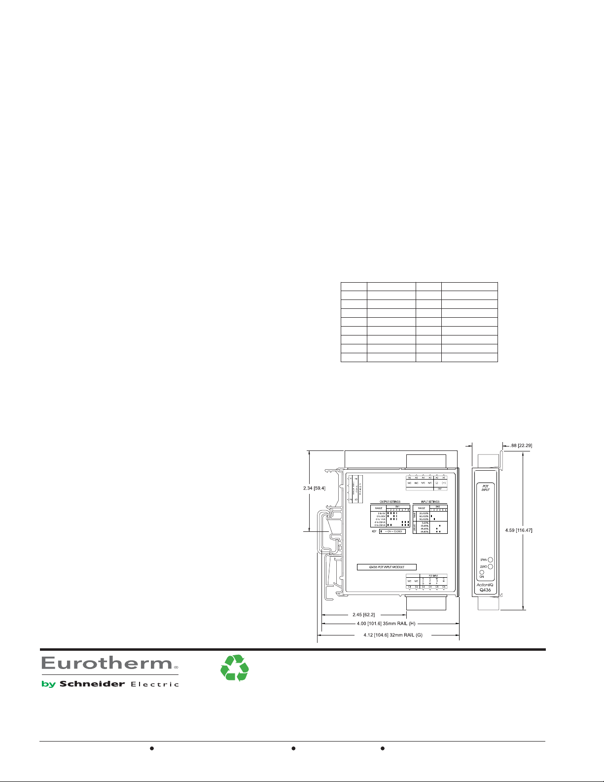
Dimensions
Action Instruments
Chessell
Eurotherm
 Loading...