

Page 1

ULTRA SLIMPAK
®
G408-0001 & G408-1001
DC Powered DC Input Field
Configurable Isolator
G408-0001 (standard outputs)
G408-1001 (bipolar outputs)
Eliminates Ground Loops
Field Configurable Input Ranges: 10mV to 100V,
1mA to 100mA
Field Configurable Output Ranges: 0-5V, 0-10V,
0-1mA, 0-20mA, 4-20mA, ±5v, ±10V
Description
The Ultra SlimPak G408 is a DIN rail mount, DC input signal
conditioner with 1800VDC isolation between input, output and
power. The field configurable input and output offers flexible,
wide ranging capability for DC current and voltage signals.
The input can be configured for any one of 12 voltage ranges from
10mV to 100V or 6 current ranges from 1mA to 100mA (see Table
1). The output is linear to the input and can be set for either 05V, 0-10V, 0-1mA, 0-20mA or 4-20mA (for models G408-0001)
and -5 to +5V or -10 to +10V (for model G408-1001).
Wide ranging, precision zero and span pots allow 50% adjustability
of offset and span turn-down within each of the 18 switch
selectable ranges. For example, the 0-2mA input range could be
turned down to 0-1mA and provide a full scale output signal (e.g.
4-20mA), or turned down and offset to achieve a 1-2mA/4-20mA
I/O combination.
Provides a Fully Isolated DC Output
in Proportion to a DC Input
Ultra Slim Housing for High Density Installations
Flexible Power Supply Accepts 9 to 30 VDC
ASIC Technology
RoHS Compliant
Configuration
The G408 has 18 input range settings. Trim potentiometers allow
50% input zero and span adjustability within each of the 18 full
scale input ranges.
Unless otherwise specified, the factory presets the Model G4080001 and G408-1001 as follows:
G408-0001
Input Range:
Output Range:
G408-1001
Input Range: 4-20mA
Output Range: -10 to +10V
The DC power input accepts any source between 9 and 30V;
typically a 12V or 24VDC source is used (see Accessories).
4-20mA
4-20mA
The G408 also accepts bipolar inputs (e.g. 10V range set to bipolar =
-10 to +10V) and offers selectable normal or reverse operation (e.g.
4-20mA/20-4mA). The ASIC based I/O channel is optically isolated
to 1800VDC and is transformer isolated from the power supply.
Application
The G408 is useful in eliminating ground loops, converting signal
levels, and providing signal drive. The field configurable, wide
ranging capability ensures maximum flexibility for most DC to DC
applications, minimizing spare part requirements.
Diagnostic LED
The G408 is equipped with a dual function LED signal monitor. The
green, front mounted LED indicates both DC power and input
signal status. Active DC power is indicated by an illuminated LED.
If the input signal is more than 110% of the full scale range, the LED
will flash at 8Hz. Below -10%, the flash rate is 4Hz.
To minumize interference from electrical and magnetic fields, the
use of shielded, twisted pair wires on the input and output is
recommended.
WARNING! Do not change switch settings with power applied.
Severe damage will result!
Refer to Tables 1 through 4 for the proper switch settings. Use the
switches on SW1 to select the input type (voltage or current) and
also to select the desired input range and function setting. Use
SW2 to select the desired output type.
Page 2

Figure 1: G408 Block Diagram
1001-804G
segnaRsegnaR
segnaR
segnaRsegnaR
1WSrotceleS
901
V5+otV5-
V01+otV01-
:yeK desolCroNO=1=
Calibration
1. After configuring the DIP switches, connect the input to a calibrated
DC source. Connect the output to the actual device load (or a load
approximately equivalent to the device load) and apply power.
Note: To maximize thermal stability, final calibration should be
performed in the operating installation, allowing approximately 1
to 2 hours for warm up and thermal equilibrium of the system.
2. Set the calibrator to the desired minimum input and adjust the
zero potentiometer for the desired minimum output.
3. Set the calibrator to the desired maximum input and adjust the
span potentiometer for the desired maximum output.
4. Repeat steps 2 and 3, as necessary, for best accuracy.
Table 1: G408 Input Range Settings
segnaR1WSrotceleS
egatloVtnerruC 12 34
Vm02Am2
Vm05Am5
Vm001Am01
Vm002Am02
Vm005Am05
V1Am001
V2
V5
V01
V52
V05
V001
:yeK desolCroNO=1=
Table 2: G408 Function Settings
1WSrotceleS
:yeK desolCroNO=1=
noitcnuF
tupnIralopinU
tuptuOesreveR
tupnItnerruC
tupnIegatloV
5678
Table 3: G408-0001 Output Settings
2WSrotceleS
:yeK desolCroNO=1=
1000-804G
segnaRsegnaR
segnaRsegnaR
segnaR
12 34 5 6 78
V5ot0
V01ot0
Am1ot0
m02ot4
Am02ot0
Table 4: G408-1001 Output Settings
Page 3
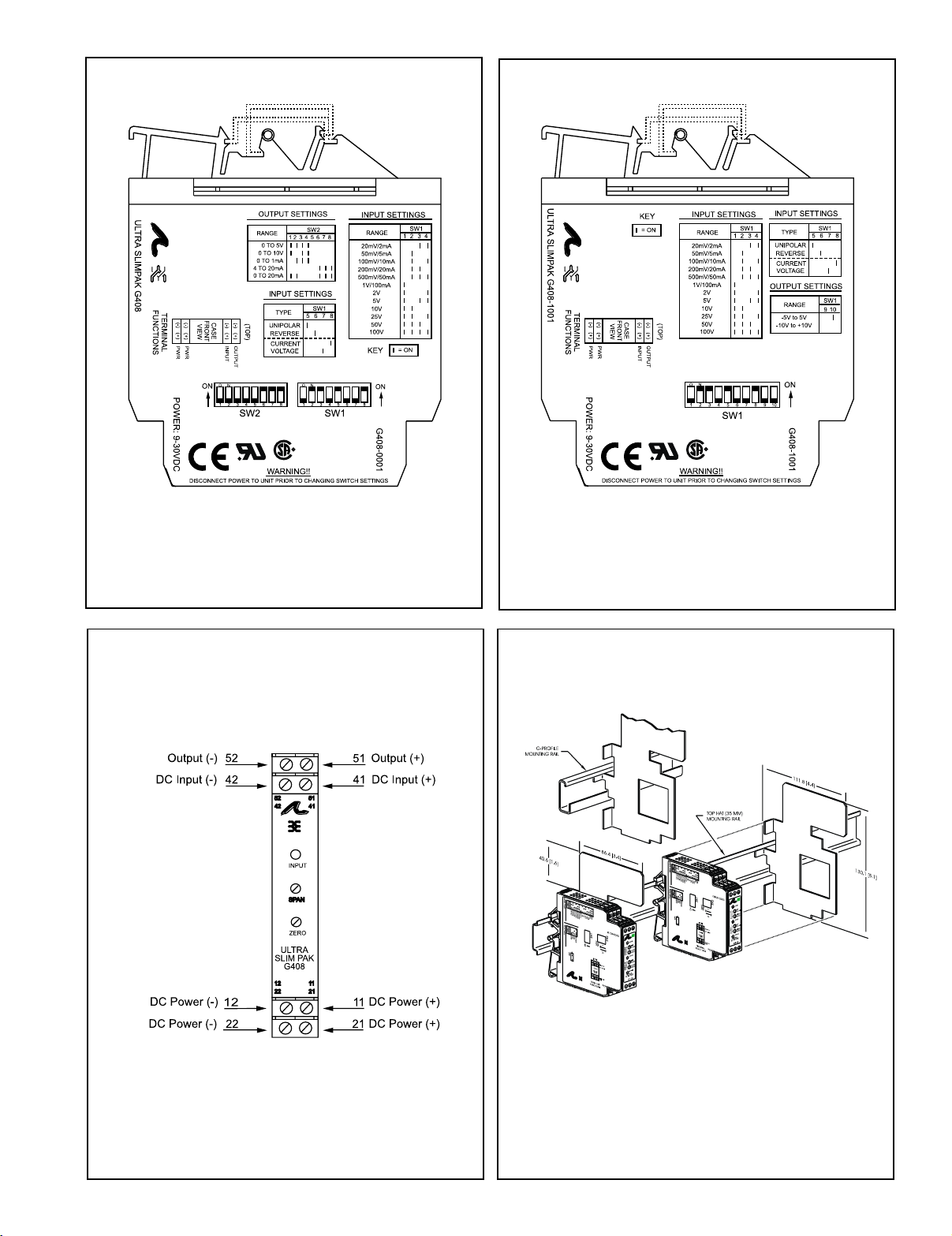
Figure 2: G408-0001 Factory Cal; 4-20mA,
Unipolar Input, Normal Operation, 4-20mA Output.
Figure 3: G408-1001 Factory Cal; 4-20mA,
Unipolar Input, Normal Operation -10 to 10V Output.
Figure 4: Wiring Diagram for G408-0001 and G408-1001
Note: All Ultra SlimPak modules are designed to operate in ambient
temperatures from 0 to 55°C when mounted on a horizontal DIN rail. If
five or more modules are mounted on a vertical rail, circulating air or
model HS01 Heat Sink is recommended. Refer to HS01 Technical
Bulletin (#721-0549-00) or contact the factory for assistance.
Figure 5: Mounting Multiple Modules
Page 4

Specifications
r
Input:
Voltage:
Range Limits: 10mV to 100V
Impedance: >100K Ohms
Overvoltage:
400 Vrms, max.(Intermittent);
264 Vrms,max. (Continous)
Current:
Range Limits: 1mA to 100mA
Impedance: 20 Ohms, typical
Overcurrent: 170mA RMS, max.
Overvoltage: 60VDC
Zero Turn-Up: 50% of full scale input
Span Turn-Down: 50% of full scale input
Common Mode (Input to Gnd): 1800 VDC, max.
Output (G408-0001):
Voltage:
Output: 0-5V, 0-10V
Source Impedance: <10 Ohms
Drive: 10mA, max.
Current:
Output: 0-1mA,4-20mA,0-20mA
Source Impedance: >100K Ohms
Compliance:
0-1mA: 7.5V, max (7.5K Ohms)
4-20mA: 12V, max (600 Ohms)
0-20mA: 12V, max (600 Ohms)
Output (G408-1001):
Voltage:
Output: -5V to +5V, -10 to +10V
Source Impedance: <10 Ohms
Drive: 10mA, max.
LED Indication (green):
Input Range
>110%(approx) input:8Hz flash
< -10%(approx) input: 4Hz flash
Accuracy (Including Linearity, Hysteresis):
<2mA/<20mV:± 0.35% of full scale,
typical; 0.5%,max.
>2mA/>20mV:± 0.1% of full scale,
typical; 0.2%, max.
Response Time (10-90%):
200mSec., typical
Stability (Temperature):
±0.025% of full scale/°C,typical; ±0.05%/°C, max.
Common Mode Rejection:
DC to 60Hz: 100dB
Isolation (Input to Output):
1800VDC between input, output & power
EMC Compliance (CE Mark):
EMC: EN61326-1:2013
Safety: EN61010-2:2013
Mean Time Between Failures:
60K Hours
Humidity (Non-Condensing):
Operating: 15 to 95% @ 45°C
Soak: 90% for 24 hours @ 65°C
Temperature Range:
Operating: 0 to 55°C (32 to 131°F)
Storage: -25 to 70°C (-13 to 158°F)
Wire Terminals:
Screw terminals for 12-22AWG
Power:
Consumption: 1.5W typical, 2.5W max.
Range: 9 to 30VDC
Weight:
0.5 lbs.
Agency Approvals:
CSA certified per standard C22.2, No. 0-M91
and 142-M1987 (File No. LR42272).
UL recognized per standard UL508
(File No.E99775).
CE Conformance per EMC directive 2004/
108/EC and Low Voltage directive 2006/
95/EC.
RoHS Compliant
Ordering Information
Models & Accessories
Specify:
1. Model: G408-0001 (standard outputs) or
G408-1001 (bipolar outputs)
2. Accessories: (see Accessories)
3. Optional Custom Factory Calibration; specify C620 with desired
input and output range.
Accessories
SlimPak "G" series modules will mount on standard TS32 (model MD02)
or TS35 (model MD03) DIN rail and include model HS01 heat sink. In
addition, the following accessories are available:
MD03 TS35x7.5 DIN rail
WV905 24VDCPower Supply (0.5 Amp)
H910 24VDC Power Supply (1 Amp)
H915 24VDC Power Supply (2.3 Amp)
MB03 End Bracket for MD03
C664 I/O Descriptive Tags
C006 0.1 Ohm, 5W, 1% shunt resistor
Printed on recycled pape
Dimensions
Action Instruments
Chessell
Eurotherm
 Loading...