

Page 1

G118-0002
ULTRA SLIMPAK
®
G118-0002
DC Powered RTD Input Limit Alarm
Provides Relay Contact Closures
at a Preset RTD/Resistance Input Level
Programmable HI or LO, Failsafe or Non-failsafe
Field Configurable Ranges for Platinum, Nickel
and Copper RTDs
Ultra Slim Housing for High Density Installations
Description
The Ultra SlimPak G118 is a DIN rail mount, RTD input limit alarm
with dual setpoints and two contact closure outputs. The field
configurable input and alarm functions offer flexible setpoint
capability. There are up to eight temperature ranges available for
each RTD type to ensure accuracy and maximize setpoint resolution.
The G118 is configurable as a single or dual setpoint alarm, with
HI or LO trips and failsafe or non-failsafe operation. Also included
are adjustable deadbands (0.25 to 5% of full scale input) for each
setpoint and a flexible DC power supply which accepts any voltage
between 9 and 30VDC.
Diagnostic LEDS
The G118 is equipped with three front panel LEDs. The dual
function green LED is labeled INPUT and indicates line power and
input signal status. Active DC power is indicated by an illuminated
LED. If this LED is off, check DC power and the wiring connection.
If the input signal is more than 110% of the full scale range, the LED
will flash at 8 Hz. Below 0%, it flashes at 4 Hz. Two red LEDs indicate
the relay state for each setpoint. An illuminated red LED indicates
the tripped condition.
LED Trip and Input Indicators
Flexible Power Supply Accepts 9 to 30 VDC
ASIC Technology for Enhanced Reliability
RoHS Compliant
Dynamic Deadband
Circuitry in the G118 prevents false trips by repeatedly sampling
the input. The input must remain beyond the setpoint for 100
milliseconds, uninterrupted, to qualify as a valid trip condition.
Likewise, the input must fall outside the deadband and remain
there for 100 milliseconds to return the alarm to an untripped
condition. This results in a “dynamic deadband” (based on time)
in addition to the normal deadband.
Configuration
Unless otherwise specified, the factory presets the Model G118 as
follows:
Input:
Range: 0 to 250°C
Output: Dual, SPDT
Failsafe: No
Deadband: A, B: 1.0%
The DC power input accepts any DC source between 9 and 30V;
typically a 12V or 24VDC source is used (see Accessories).
Platinum (100 Ohm)
Trip: A:HI, B:LO
Output
The G118 is equipped with two SPDT (form C) relays, rated at
120VAC or 28VDC at 5 Amperes. Each of these relays is independently controlled by the field configurable setpoint and
deadband.
Operation
The field configurable G118 limit alarm setpoints can be configured for HI or LO, failsafe or non-failsafe operation. Each of the
setpoints has a respective HI or LO deadband. In a tripped
condition, the setpoint is exceeded and the appropriate red LED
will illuminate. The trip will reset only when the process falls below
the HI deadband or rises above the LO deadband (see Figure 1).
For proper deadband operation the HI setpoint must always be set
above the LO setpoint. In failsafe operation, the relay is energized
when the process is below the HI setpoint or above the LO setpoint
(opposite for non-failsafe). In the failsafe mode, a power failure
results in an alarm state output.
For other I/O ranges, refer to Tables 1 through 3 and reconfigure
switches SW1 and SW2 for the desired input type, range and function.
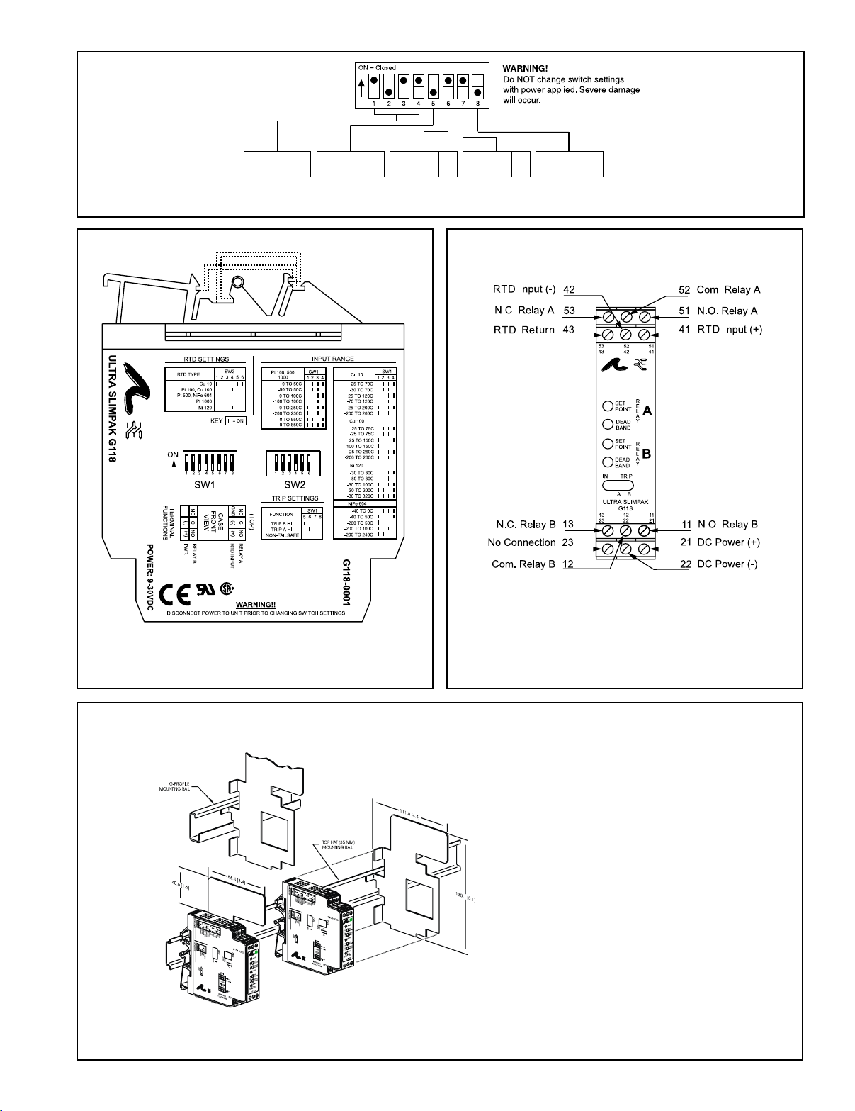
WARNING: Do not change switch settings with power applied.
Severe damage will result!
1. With DC power off, position input switches 1 through 6 on
“SW2” for RTD type (Table 1).
2. Set position 1 through 4 of input range switch “SW1” for the
desired RTD type and input temperature range (Table 3).
3. Set position 5 and 6 of input range switch “SW1” to ON for a HI
trip setpoint or OFF for a LO trip setpoint (Figure 4).
4. Set position 7 of input range switch “SW1” to ON for non-failsafe
operation or OFF for failsafe operation (e.g. alarm trips upon
power failure).
Page 2
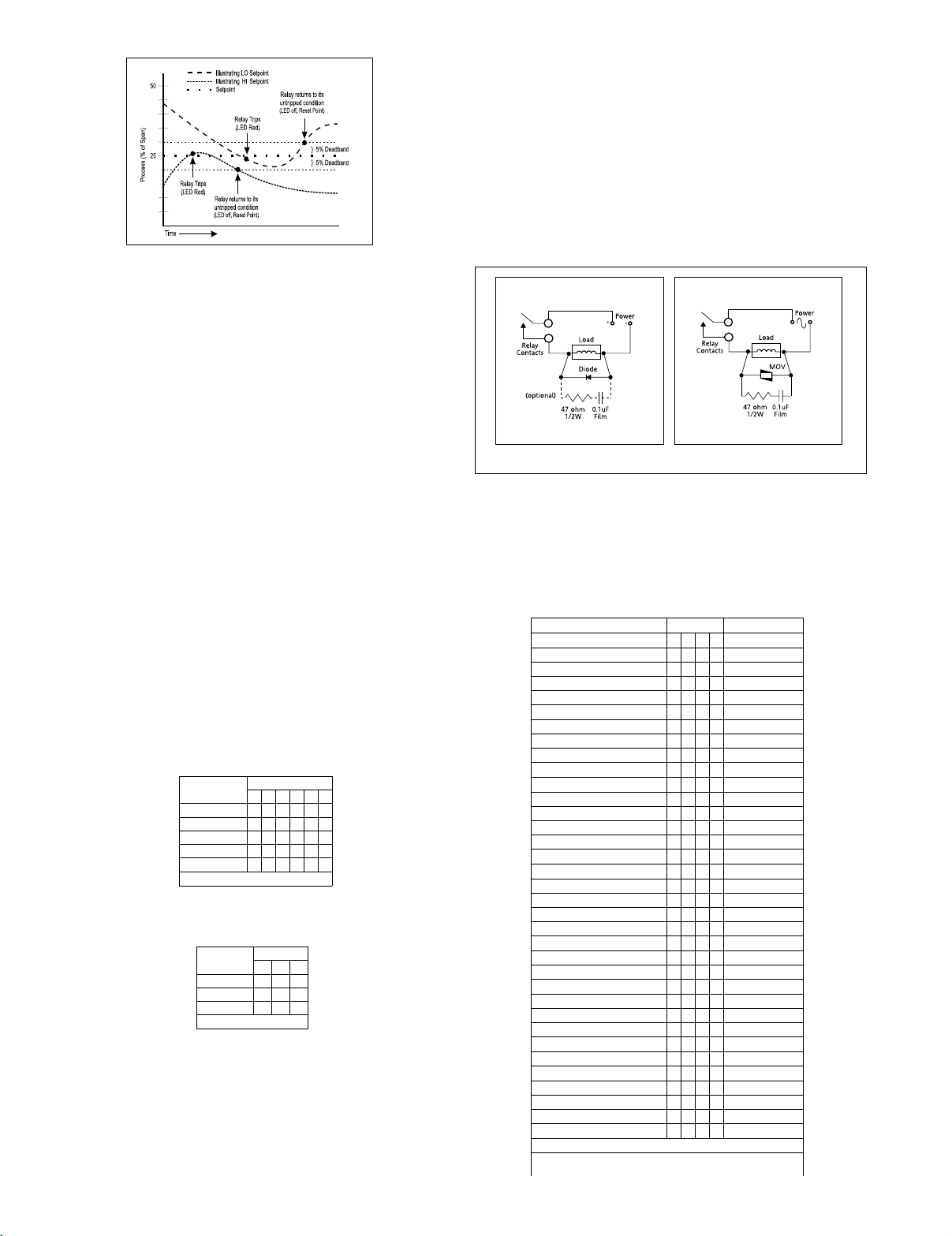
Figure 1: Limit alarm operation and effect of deadband.
Calibration
1. After configuring the DIP switches, connect the input to a
calibrated RTD source or a resistance decade box and apply power.
Note: To maximize thermal stability, final calibration should be
performed in the operating installation, allowing approximately 1
to 2 hours for warm up and thermal equilibrium of the system.
2. Setpoint Calibration: Before adjusting the setpoint, adjust the
deadband pot to its minimum (fully counterclockwise). With the
desired trip RTD resistance input applied, adjust the setpoint pot
until the relay trips. For HI trip calibration, start with the setpoint
pot above the desired trip (fully clockwise). For LO trip
calibration, start with the setpoint pot below the desired trip (fully
counterclockwise).
Relay Protection & EMI Suppression
When switching inductive loads, maximum relay life and transient
EMI suppression is achieved using external protection (see Figures
2 and 3). Place all protection devices directly across the load and
minimize all lead lengths. For AC inductive loads, place a properly
rated MOV across the load in parallel with a series RC snubber. Use
a 0.01 to 0.1uF pulse film capacitor (foil polypropylene recommended) of sufficient voltage, and a 47 ohm, 1/2W carbon
resistor. For DC inductive loads, place a diode across the load (PRV
> DC supply, 1N4006 recommended) with (+) to cathode and (-) to
anode (the RC snubber is an optional enhancement).
Figure 2: DC Inductive Loads
Figure 3: AC Inductive Loads
3. Deadband Calibration: Set the deadband pot to its minimum
(fully counterclockwise). Adjust the setpoint pot to the desired
trip. Adjust the RTD resistance input until the relay trips. Readjust
the deadband pots to 5% (fully clockwise). Set th RTD resistance
input to the desired deadband position. Slowly adjust deadband
(counterclockwise) until the relay untrips.
Table 1: G118 RTD Type Settings
2WSrotceleS
:yeK desolCroNO=1=
epyTDTR
123 45 6
01uC
001uC,001tP
406eFiN,005tP
0001tP
021iN
Table 2: G118 Trip Settings
noitcnuF
IHBpirT
IHApirT
efasliaF-noN
:yeK desolCroNO=1=
1WSrotceleS
567
Table 3: G118 Range Settings
egnaRtupnIDTR1WSrotceleS)smhO(ecnatsiseR
)58300.0=ahpla(0001,005,001tP 123 4 001tP*
)F¡221ot23(C¡05ot0
)F¡221ot85-(C¡05ot05-
)F¡212ot23(C¡001ot0
)F¡212ot841-(C¡001ot001-
)F¡284ot23(C¡052ot0
)F¡284ot823-(C¡052ot002-
)F¡2201ot23(C¡055ot0
01uC 123 4 01uC
001uC 123 4 001uC
021iN 12 34 021iN
406eFiN 123 4 406eFiN
:yeK desolCroNO=1=
)F¡2651ot23(C¡058ot0
)F¡851ot77(C¡07ot52
)F¡851ot22-(C¡07ot03-
)F¡842ot77(C¡021ot52
)F¡842ot49-(C¡021ot07-
)F¡005ot77(C¡062ot52
)F¡005ot823-(C¡062ot002-
)F¡761ot77(C¡57ot52
)F¡761ot31-(C¡57ot52-
)F¡203ot77(C¡051ot52
)F¡203ot841-(C¡051ot001-
)F¡005ot77(C¡062ot52
)F¡005ot823-(C¡062ot002-
)F¡68ot22-(C¡03ot03-
)F¡68ot211-(C¡03ot08-
)F¡212ot22-(C¡001ot03-
)F¡293ot22-(C¡002ot03-
)F¡806ot22-(C¡023ot03-
)F¡23ot04-(C¡0ot04-
)F¡221ot04-(C¡05ot04-
)F¡221ot823-(C¡05ot002-
)F¡212ot823-(C¡001ot002-
)F¡464ot823-(C¡042ot002-
4.911ot001
5.831ot001
5.831ot2.06
1.491ot001
1.491ot5.81
4.792ot001
3.093ot001
47.11ot0.01
47.11ot678.7
76.31ot0.01
76.31ot813.6
611.91ot0.01
611.91ot850.1
5.511ot001
5.511ot7.08
3.841ot001
3.841ot3.15
2.191ot001
2.191ot6.01
1.241ot4.99
1.241ot6.66
6.002ot4.99
5.303ot4.99
2.174ot4.99
0.406ot1.994
8.157ot1.994
8.157ot3.542
3.719ot3.542
6.5741ot3.542
ecnatsiserehtsemit01dna5era0001tPdna005tProfseulavecnatsiseR*
Page 3
Input Range
See T able 3
"B" LO Trip
"B" HI Trip
Off
On
"A" LO Trip
"A" HI Trip
Off
On
Failsafe
Non-failsafe
Off
On
Not Used
Figure 4: G118 Input Range/Function Selection (SW1) Factory Default Settings
Figure 5: G118 Factory Cal; 0-250°C (Pt 100),
A-HI/B-LO, Non-Failsafe
Figure 7: Mounting Multiple Modules
Figure 6: Terminal Wiring Diagram for G118
Note: All Ultra SlimPak modules are designed to operate in ambient
temperatures from 0 to 55°C when mounted on a horizontal DIN rail. If
five or more modules are mounted on a vertical rail, circulating air or
model HS01 Heat Sink is recommended. Refer to HS01 Technical
Bulletin (#721-0549-00) or contact the factory for assistance.
Page 4

Specifications
Inputs
Sensors:
Pt100, Pt500, Pt1000 (0.00385Ohms/Ohm/°C);
Cu10, Cu100; Ni120, NiFe604
Sensor Connection: 3-wire.
Input Ranges: See table 1.
Excitation Current (Max)
<2mA for Pt100, Pt500, Pt1000, Ni120,
Cu100 or NiFe604
<10mA for Cu10
Leadwire Resistance
40% of base sensor resistance or 100 Ohms
(whichever is less), maximum per lead.
Leadwire Effect
Less than 1% of selected span over entire
leadwire resistance range.
Input Protection
Normal Mode: Withstands ±5VDC.
Common Mode (Input to Gnd): 1800VDC, max.
LED Indicators
Input Range (Green):
>110% input: 8Hz flash;
>-10% input: 4Hz flash
Setpoint (Red):
Tripped: Solid red;
Safe: Off
Limit Differentials (Deadbands)
0.25% to 5% of span
Response Time
Dynamic Deadband:
Relay status will change when proper
setpoint/ process condition exists for
100msec.
Normal Mode (analog filtering):
<250mSec, (10-90%)
Setpoints
Effectivity:
Setpoints are adjustable over 100% of
the selected input span
Repeatability (constant temp.):
±0.2% of full scale
Stability
Line Voltage: ±0.01%/%, max.
Temperature: ±0.05% of full scale/°C, max.
Common Mode Rejection
DC to 60Hz: 120dB
>60Hz: 100dB
Isolation
1800VDC between contacts, input & power
EMC Compliance (CE Mark)
EMC: EN61326-1:2013
Safety: EN61010-2:2013
Humidity (Non-Condensing)
Operating: 15 to 95% @45°C
Soak: 90% for 24 hours @65°C
Temperature Range
Operating: -15 to 55°C (5 to 131°F)
Storage: -25 to 75°C (-13 to 158°F)
Power
Consumption: 1.5W typical, 2.5W max.
Supply Range: 9 to 30VDC, inverter isolated
Relay Contacts
2 SPDT (2 form C) Relays, 1 Relay per
setpoint
Current Rating (resistive)
120VAC: 5A; 240VAC: 2A; 28VDC: 5A
Material: Gold flash over silver alloy
Electrical Life:10
Note: External relay protection is required
for use with inductive loads (see Figures 2 & 3).
Mechanical Life: 10
Weight
0.56lbs.
Agency Approvals
CSA certified per standard C22.2, No. 0-M91
and 142-M1987 (File No. LR42272)
UL recognized per standard UL508
(File No.E99775)
CE Conformance per EMC directive 2004/
108/EC and Low Voltage directive 2006/
95/EC.
RoHS Compliant
5
operations at rated load
7
operations
Ordering Information
Models & Accessories
Specify:
1. Model: G118-0002
2. Accessories: (see Accessories)
3. Optional Custom Factory Calibration; specify C620 with desired
input and output range.
Accessories
SlimPak “G” series modules will mount on standard TS32 (model MD02) or TS35
(model MD03) DIN rail . In addition, the following accessories are available:
HS01 Heat Sink
MD03 TS35 x 7.5 DIN Rail
WV905 24VDC Power Supply (0.5 Amp)
H910 24VDC Power Supply (1Amp)
H915 24VDC Power Supply (2.3 Amp)
MB03 End Bracket for MD03
C664 I/O Descriptive Tags
Schneider Electric Systems USA, Inc.
44621 Guilford Drive, Suite 100
Ashburn, VA 20147
703-724-7300
info@eurotherm.com or www.eurotherm.com/actionio
Action Instruments
Dimensions
Factory Assistance
For additional information on calibration, operation and installation
contact our Technical Services Group:
703-724-7314
actionsupport@eurotherm.com
721-0651-00-H 09/06 Copyright© Eurotherm, Inc 2006
Chessell
Eurotherm
 Loading...