

Page 1
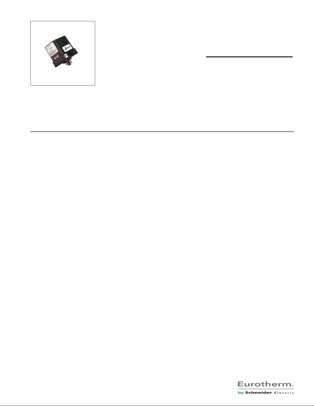
AP7500-5012 (0-20mA in; square wave output)
AP7500-5016 (4-20mA in; square wave output)
AP7500-5065 (0-1Vdc in; square wave output)
AP7500-5068 (0-5Vdc in; square wave output)
AP7500-5070 (0-10Vdc in; square wave output)
AP7500-5085 (1-5Vdc in; square wave output)
AP7501-6007 (0-1mA in; relay contact output)
AP7501-6012 (0-20mA in; relay contact output)
AP7501-6016 (4-20mA in; relay contact output)
AP7501-6065 (0-1Vdc in; relay contact output)
AP7501-6068 (0-5Vdc in; relay contact output)
AP7501-6070 (0-10Vdc in; relay contact output)
AP7501-6085 (1-5Vdc in; relay contact output)
Action PAK
®
AP7500 & AP7501
DC to Frequency Converters
Provides a Field Selectable Frequency Output
in Proportion to a DC Input
Switch Selectable Output Range
Adjustable Low End Cutout (0-10%)
Totalization/Integration Applications
Application
The AP7500 and AP7501 are useful in totalizing applications, where
the total number of pulses counted in a given time period
represents the time integral of the DC input. If, for example, the
input represents a flow in gallons per hour, then the time integral
of this flow signal (total count) will represent total gallons. The
AP7500’s 6V square wave output can be used to drive electronic
counters (DTL, TTL, CMOS). The AP7501 can be used to drive
electromechanical counters when connected to an external AC or
DC power source. In the AP7501, the DPDT relay contacts are
pulsed (closed) for only a short duration (100 milliseconds) for
compatibility with standard electromechanical counters. The
AP7500 can also be used in telemetry systems, where the dc signal
is converted to a frequency, transmitted over long lines, and then
decoded at the receiving end by means of a frequency to DC
converter, such as the AP7380.
Options
CS Canadian Standards Association Certification.
U Urethane coating of internal circuitry for protection from
corrosive atmospheres.
C Open collector output instead of the standard 6V output,
sinks up to 50mA, up to 30V (AP7500 only).
Output Ranges
The output frequency range is selectable via the 16-position rotary
switch accessible through the top cover. See tables 1 and 2 for
output selection. Since ranging is accomplished through digital
circuitry, the accuracy of the unit is unaffected by the switch
position; each successive position exactly halves (clockwise) or
doubles (counterclockwise) the previous output frequency (see
“Calibration”).
Plug-In Installation
Square Wave (AP7500) or Relay Contact (AP7501) Output
Selectable 120/240VAC Input Power
Input Ranges
Standard input ranges and limits are included in Tables 3 and 4.
Cutout
The top accessed Cutout adjustment determines the input (level)
at which the AP7500 or AP7501 no longer responds (i.e., the unit
is effectively “off”) and is adjustable from 0-10% of the input span.
This feature is especially useful with low frequency spans, where
the time between output pulses is excessively long at low input
levels. A light-emitting diode (LED) visible through the top-cover
aids in adjusting cutout. This LED lights when the unit is no longer
responding to the input. With the input at the desired cutout level,
adjust Cutout slowly clockwise until the LED lights. Then turn the
adjustment counterclockwise until the LED just goes out. Cutout
is now set for the input level present.
Calibration
Zero, Span and Low-End Cutout adjustments are screwdriver
adjustable, accessible through the top cover.
Zero and Span: Monitor the unit’s output using an accurate
frequency counter. Apply an input equal to 5% of the specified
input span. If the cutout LED (visible through the top cover) is lit,
adjust Cutout counterclockwise until it turns off. Adjust Zero for
5% of the desired full scale output frequency. Apply full scale input
and adjust Span for the desired maximum output frequency.
Repeat these adjustments for best accuracy.
Note: For faster calibration of low frequency spans, use the range
selector switch to multiply the output frequency. Each position
counterclockwise exactly doubles the output frequency. After
calibration, return the selector switch to the proper range position.
Page 2
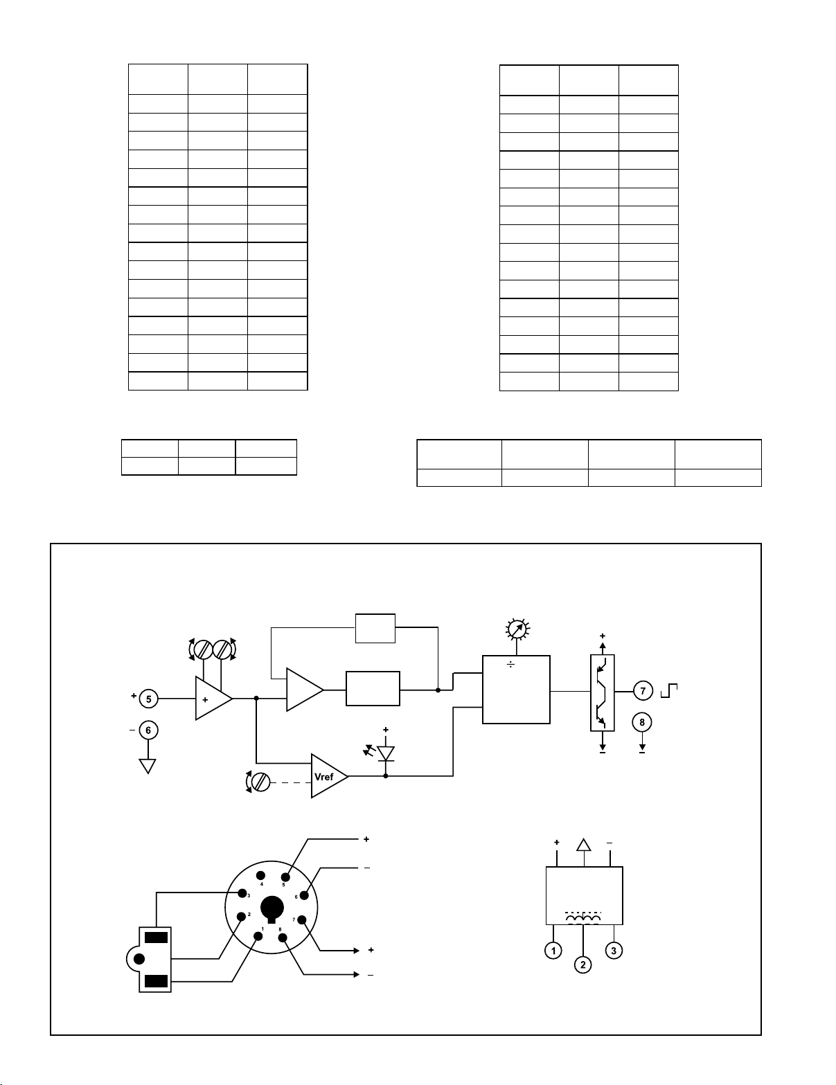
Table 1: AP7500 Output Ranges
y
hctiwS
noitisoPnoitisoP
noitisoPnoitisoP
noitisoP
0zHk5-0zHk01-0
1zHk5.2-0zHk5-0
2zHk52.1-0zHk5.2-0
3zH526-0zHk52.1-0
4zH213-0zH526-0
5zH651-0zH213-0
6zH87-0zH651-0
7zH93-0zH87-0
8zH02-0zH93-0
9zH01-0zH02-0
AzH5-0zH01-0
BzH5.2-0zH5-0
CzH52.1-0zH5.2-0
Dmpp63-0zH52.1-0
Empp81-0mpp63-0
Fmpp9-0mpp81-0
muminiM
egnaRegnaR
egnaRegnaR
egnaR
mumixaM
egnaRegnaR
egnaRegnaR
egnaR
Table 2: AP7501 Output Ranges
hctiwS
noitisoPnoitisoP
noitisoPnoitisoP
noitisoP
0mpp56-0mpp031-0
1mpp23-0mpp56-0
2mpp61-0mpp23-0
3mpp8-0mpp61-0
4mpp4-0mpp8-0
5mpp2-0mpp4-0
6mpp1-0mpp2-0
7mpp5.0-0mpp1-0
8mpp52.0-0mpp5.0-0
9hpp8-0hpp61-0
Ahpp4-0hpp8-0
Bhpp2-0hpp4-0
Chpp1-0hpp2-0
Dhpp5.0-0hpp1-0
Ehpp42.0-0hpp5.0-0
Fhpp21.0-0hpp42.0-0
muminiM
egnaRegnaR
egnaRegnaR
egnaR
mumixaM
egnaRegnaR
egnaRegnaR
egnaR
Table 3: AP7500/AP7501 Standard Inputs
V1ot0V5ot1Am02ot4
V5ot0V01ot0Am05ot01
AP7500 Functional Diagram/Pin Connections
Zero
Span
DC
Input
Input
Amplifier
Cutout
Differential
Amplifier
Comparator
Averaging
Circuit
Voltage-Controlled
Oscillator
Cutout
Calibration
LED
Table 4: AP7500/AP7501 Input Limits
napSmuminiM
)egatloV()egatloV(
)egatloV()egatloV(
)egatloV(
Vm002Am1V002Am001
Range
Selector
n
2
Input
Output
Inhibit
Programmable
Divider
napSmuminiM
)tnerruC()tnerruC(
)tnerruC()tnerruC(
)tnerruC(
Push-Pull
Output Stage
tupnImumixaM
)egatloV()egatloV(
)egatloV()egatloV(
)egatloV(
Frequenc
Output
tupnImumixaM
)tnerruC()tnerruC(
)tnerruC()tnerruC(
)tnerruC(
AC (Neu)
(Shield)
GND
AC (Hot)
DC Input
NOTE: Input and Output are
referenced to different levels.
DO NOT Ground both.
Frequency
Output
Transformer
Isolated
Power Supply
AC AC
Shield
Page 3
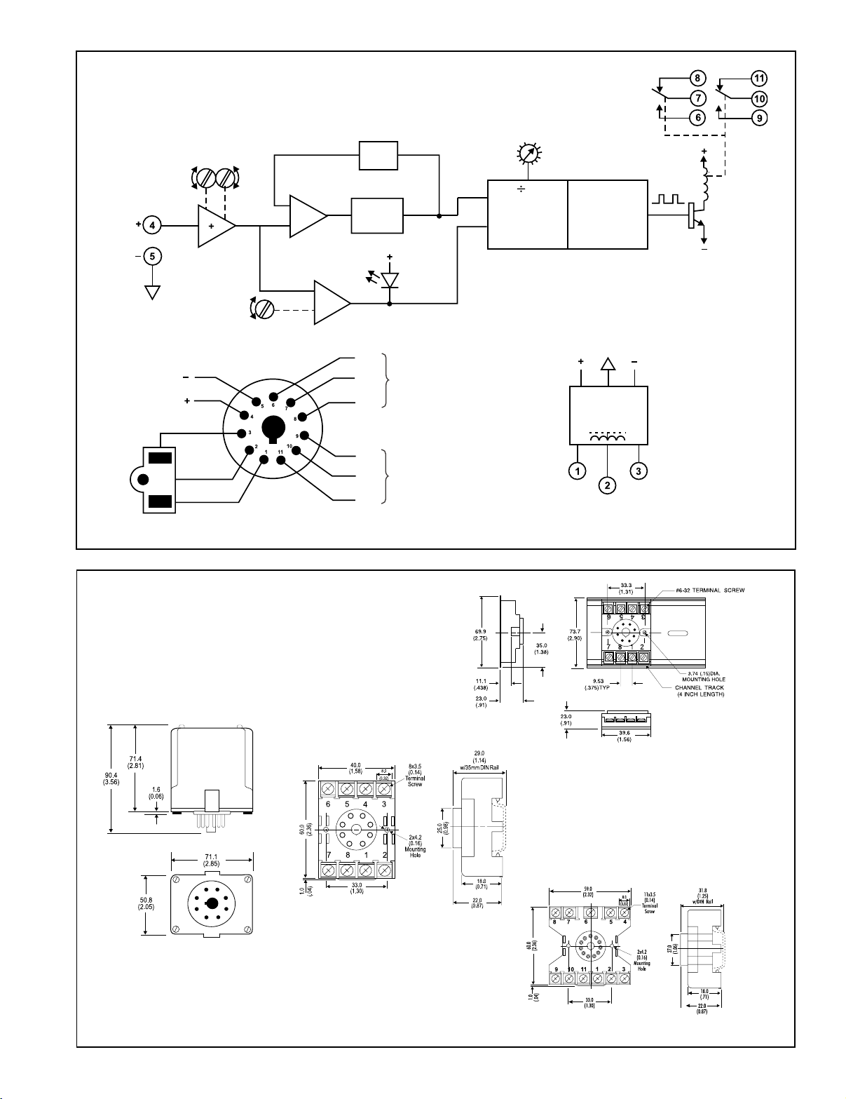
AP7501 Functional Diagram/Pin Connections
Zero
Span
DC
Input
Input
Amplifier
Differential
Amplifier
Comparator
Averaging
Circuit
Voltage-Controlled
Oscillator
Range
Selector
n
2
Input
Inhibit
Programmable
Divider
Output
Monostable
Multivibrator
(One-Shot)
CC
NO NO
Relay
Relay
Driver
Cutout
Cutout
Calibration
LED
NO
Relay Contact
C
DC Input
Set 1
NC
AC (Neu)
(Shield)
GND
NO
C
Relay Contact
Set 2
NC
AC (Hot)
Mounting
All Action Paks feature plug-in installation. The Action Pak AP7500
uses an 8-pin base and AP7501 uses an 11-pin base and either molded
socket M008/M011, or DIN-Rail MD08/MD11 mounting sockets.
Dimensions
Dimensions are in millimeters (inches)
Transformer
Isolated
Power Supply
AC AC
Shield
Mark II
M008 (8 pin) shown, and
M011 (11 pin) (Track/Surface)
MD08 (DIN/Surface)
MD11 (DIN-Rail)
Page 4

Specifications
r
Input Impedance:
Voltage Input: Greater than 100KW
Current Input: Less than 500mV shunt @
full scale (e.g. 20W for 20mA)
Input Protection: Withstands 200% of span
Linearity (Best Straight Line & Linear Input):
0.25% of span, typical
Low Input Cutout:
Adjustable, 0-10% of span (factory set at 1%),
LED cutout indication
Output:
AP7500: Square-wave, 0/6V, 1:1 mark/
space ratio, source 10mA, sink 50mA.
Option C 50mA sink, 30V.
AP7501: Isolated DPDT relay contacts,
rated 120VAC @5A or 28VDC @ 5A
(100mSec min. on time).
Contact Material: Silver Cadmium Oxide
5
Life: 10
operations at rated load
Response Time:
100 milliseconds typical, 200 milliseconds max
AP7500-5012 (0-20mA in; square wave output)
AP7500-5016 (4-20mA in; square wave output)
AP7500-5065 (0-1Vdc in; square wave output)
AP7500-5068 (0-5Vdc in; square wave output)
AP7500-5070 (0-10Vdc in; square wave output)
AP7500-5085 (1-5Vdc in; square wave output)
AP7501-6007 (0-1mA in; relay contact output)
AP7501-6012 (0-20mA in; relay contact output)
AP7501-6016 (4-20mA in; relay contact output)
AP7501-6065 (0-1Vdc in; relay contact output)
AP7501-6068 (0-5Vdc in; relay contact output)
AP7501-6070 (0-10Vdc in; relay contact output)
AP7501-6085 (1-5Vdc in; relay contact output)
Overrange Capability:
Output is linear to 120% of input
Stability:
Better than 0.05% of span per degree C
Common Mode Rejection:
DC: > 100dB
60 Hz: > 80dB
Maximum Common Mode Voltage:
50V
Temperature Range:
Operating: 0 to 60°C (32 to 140°F)
Storage: -20 to 85°C (-4 to 185°F)
Power:
Consumption: 3W typical, 5W max
Standard: 120 VAC (±10%, 50-400Hz)
Available: 240VAC (±10%, 50-400Hz)
Weight:
0.62lbs
Agency Approvals:
CSA certified per standard C22.2, No. 0-M1982
(File No. LR42272-8, 9)
Ordering Information
Specify:
1. Model: AP7500 or AP7501 (see above)
2. Options: CS, U, C (see text)
3. Input Range (see Tables 3, 4)
4. Line Power (see specs)
5. C620 Factory Calibration of input, setpoints and output relays.
Accessories:
M801-0000 Retaining Spring
M008-A 8 pin Track Mount Socket
M011-A 11 pin Track Mount Socket
M004-0000 4 ft Long Channel Track
MD08-0000 8 pin DIN Mount Socket
MD11-0000 11 pin DIN Mount Socket
Printed on recycled pape
Action Instruments
Chessell
Pin Connections
AP7500
1 AC Power (Hot)
2 Shield (Gnd)
3 AC Power (Neu)
4 No Connection
5 Input (+)
6 Input (-)
7 Output (+)
8 Output (-)
721-0148-00-W 05/08 Copyright© Eurotherm, Inc 2008
AP7501
10 C Set 2
11 N.C.
Eurotherm
1 AC Power (Hot)
2 Shield (Gnd)
3 AC Power (Neu)
4 Input (+)
5 Input (-)
6 N.O.
7 C Set 1
8 N.C.
9 N.O.
 Loading...