

Page 1
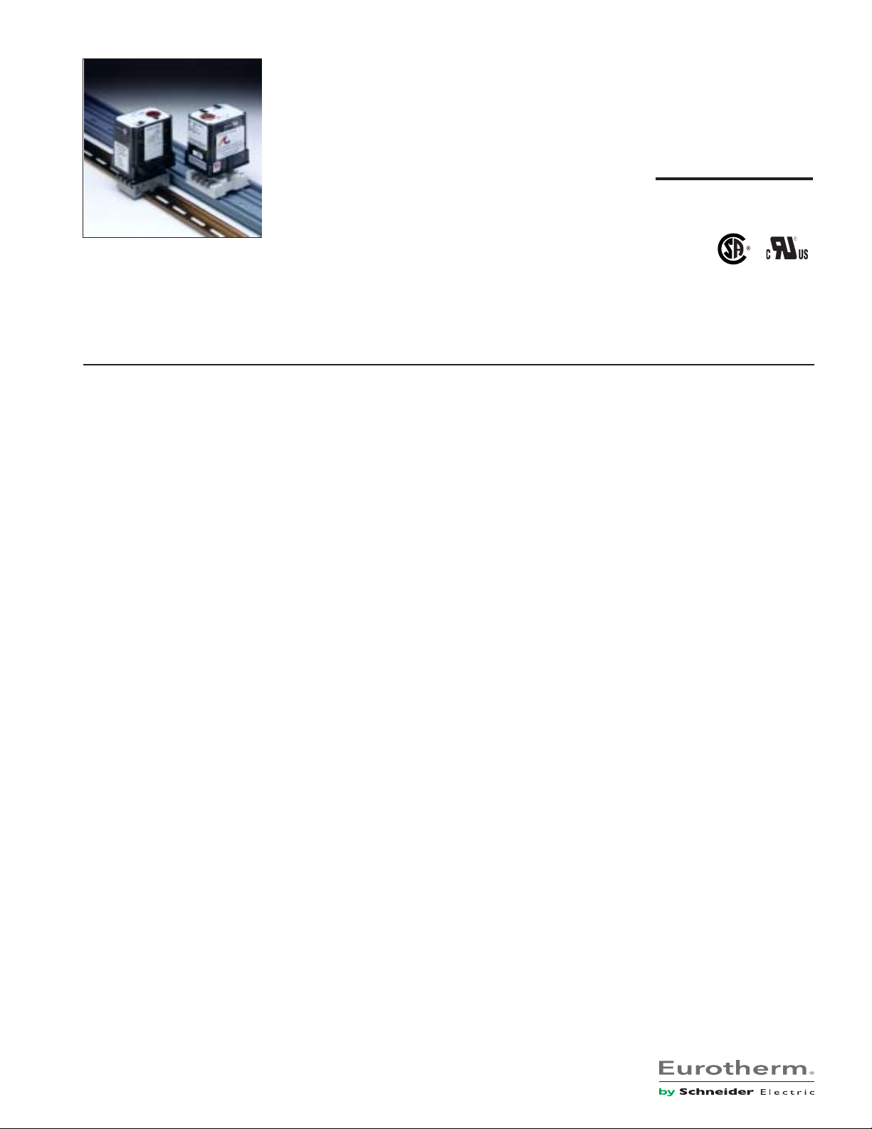
AP7380-0000
Action PAK
®
AP7380
Frequency Input, Field Configurable
Signal Conditioner
Provides an Isolated DC Output
in Proportion to Frequency Input
Field Configurable Input Rangesfrom 2Hz to 10,000Hz
Four Field Configurable Output Ranges 0-5V, 0-10V,
0-1mA, 4-20mA
Eliminates Ground Loops
Description
The Action Pak Model AP7380 is a frequency input signal conditioner with 1500VDC isolation between input, output and power.
The field configurability of the input and output offers flexible,
wide ranging capability for magnetic pick-ups, turbine flow
meters, and other pulse or frequency output transducers.
The input of the AP7380 can be configured for any frequency span
from 2Hz (e.g., 59-61Hz) to 10,000Hz. The input amplitude
threshold (SENS POT) can be adjusted from 150mVp to 10Vp to
ensure accurate frequency measurement and minimize transient
noise related errors. The maximum input amplitude is 150 Vrms.
The output can be set for either 0-5V, 0-10V,0-1mA or 4-20mA.
Advanced digital technology allows the AP7380 to be field configured to convert virtually any frequency input to a DC signal output
within the ranges specified. Calibration utilizes ‘Touch-Sample’
technology by which the user simply applies the desired input
frequency, and touches a recessed button to configure the
corresponding input range.
The convenient Action Pak is very easy to install using surface
mount, DIN rail mount or snap track mounting sockets. Trouble
shooting is very easy since no wires need to be removed when
swapping units. The wide ranging power supply can be configured
for either 120 or 240VAC power.
Plug-in Installation
Selectable 120/240VAC Input Power
ASIC Technology for Enhanced Reliability
'Touch Sample' Technology
The AP7380 utilizes Action Instruments’ ‘Touch-Sample’ technology which greatly simplifies configuration. To set the input
frequency range, the user simply applies the high input frequency
and pushes the CAL button while the INPUT LED is on. The low
input frequency is then applied and pushing the CAL button again
stores the low frequency input.
The high and low ranges are stored in non-volatile memory and
correspond to the high and low output ranges which have been
selected via DIP switches.
To precisely adjust the output, the user adjusts the input frequency while the OUTPUT LED is on until the desired output level
is achieved. The output levels are locked in by pushing the CAL
button. Status LEDs show the operational mode of the device.
Status LEDs
The AP7380 utilizes three status LEDs. The green LEVEL LED
changes in intensity with input level. Its intensity varies with the
frequency of the input signal during normal operation. If the input
signal is 10% more than full scale range, the LED will flash at 8Hz.
Below 0%, the flash rate is 4Hz.
The yellow INPUT LED, when on, denotes input programming
modes.
Application
The AP7380 field configurable, frequency input signal conditioner
is useful in eliminating ground loops and interfacing pulse output
transducers, such as turbine flow meters and magnetic pick-ups,
to data acquisition and control systems.
Advanced digital technology, combined with Action’s ASIC technology, provides a stable output at low frequencies for higher
accuracy, and three-way isolation completely eliminates ground
loops from any source.
Option
U Urethane coating of internal circuitry for protection from
corrosive atmospheres
The red OUTPUT LED, when on, denotes output programming
modes (see Configuration, Calibration and Figure 1 for details).
Configuration
A major advantage of the AP7380 is its wide ranging capabilities
and ease of configuration. The AP7380 enables virtually 99% zero
and span adjustability. Any 2Hz range from 0 to 10,000Hz can be
converted to a full scale output signal (e.g. 0-2Hz/4-20mA or 999810,000Hz/4-20mA).
Page 2
Unless otherwise specified, the factory presets are as follows:
Input Range: 0 to 1000Hz
Sensitivity: 1V peak (LO)
Output Range: 4 to 20mA
Power: 120VAC
9. Check the minimum and maximum input-to-output calibration.
Repeat steps 1 through 8 if calibration is not within desired
specifications.
Note 1: To skip Steps 6 and 7 (output adjustment), press CAL
button two times after Step 5.
Note: "Sensitivity" refers to the noise rejection level or the trigger
threshold of the input.
For other I/O ranges, refer to Table 1 for output range (SW1)
switch settings and to Figure 4 for sensitivity jumper setting (P3).
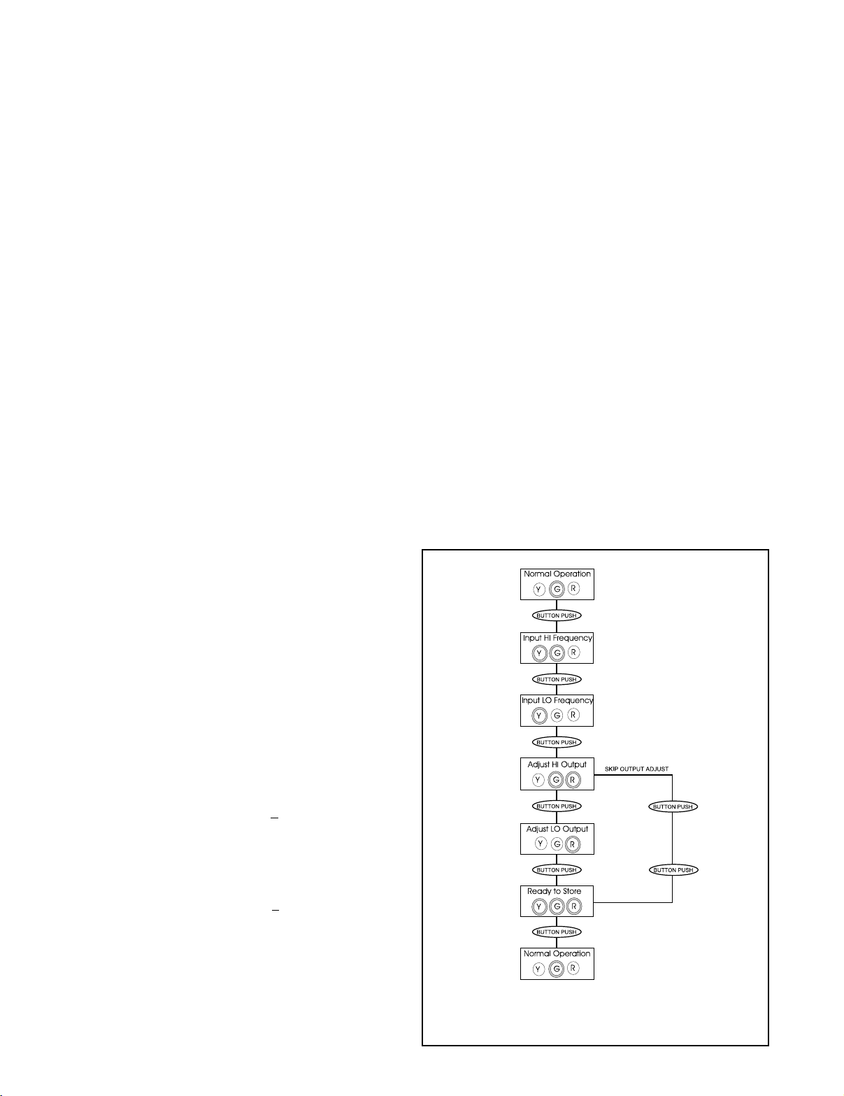
For quick and easy calibration mode reference, see the step-bystep flow chart in Figure 1.
1. With DC power off, choose the desired output voltage/current
range from Table 1 and set position 1 through 6 of the output
switch selector (SW1).
2. Set the Input sensitivity jumper (P3) to LO for input amplitudes
between 150mVp and 50Vrms, with noise rejection to 1Vp. Set P3
to HI for input amplitudes between 500mVp and 150Vrms, with
noise rejection up to 10Vp.
Calibration
1. Connect the input to a calibrated frequency source and apply
power. Wait 1 hour for thermal stability before monitoring the
voltage or current output.
2. Adjust the input frequency to the desired maximum and
observe that the output has increased and is sensing the input. If
this is not observed, turn the sensitivity potentiometer in a
counter-clockwise direction until the output changes proportionally to the input.
Note 2: Removing power to the unit at any time before Step 8 will
restore previous settings
Optimal Sensitivity
If the amplitudes of the input frequency is within the sensitivity
parameters (i.e. 150mVp - 1Vp for LO and 0.5Vp - 10Vp for HI),
then the sensitivity parameters can be set for optimum noise
rejection.
1. Set the input near midrange (50% input) or to a frequency that
exhibits the minimum pulse amplitude.
2. Turn the sensitivity pot (SENS) clockwise (CW) until the output
drops to minimum.
3. Turn the sensitivity pot counter- clockwise(CCW) until the
output returns to the previous level. A couple more CCW turns will
provide optimal noise rejection.
4. Run the input through the full frequency range to make sure
that the pulses are sensed at both the low and high input
frequencies. If the output drops out during this test, when the
input freq. >0% then turn the sensitivity pot counter -clockwise
another turn or two until the output picks up. Repeat to validate
sensitivity settings.
3. With the green LED on press the CAL button once to enter the
calibration mode. The yellow and green LEDs should now be on.
4. Input the maximum desired frequency (if not done already) and
press the CAL button to store. The yellow LED should now be the
only LED on.
5. Input the minimum desired frequency and press the CAL button
to store. The green and red LEDs should now be on.
Note: The most reliable way to input 0Hz is to short circuit the input
pins (5&6).
6. To precisely adjust the maximum output, adjust the input
frequency until the output reads within +0.1% of the maximum
selected output range. This typically occurs near 90% of the HI
input frequency. Press the CAL button to store the value. The red
LED should now be on.
7. To precisely adjust the minimum output, lower the input
frequency until the output reads within
selected ouput. This typically occurs less than 10% of the HI input
frequency. Press the CAL button to store the value. The Yellow,
Red and Green LEDs should be on (see Figure 1).
8. Press the CAL button one final time to exit the calibration mode.
The green LED should now be on. (With only 5-10% of input, the
green LED is off.)
+0.1% of the minimum
* Green LED may be very dim and appear off.
Figure 1: Calibration Flow Chart
Page 3
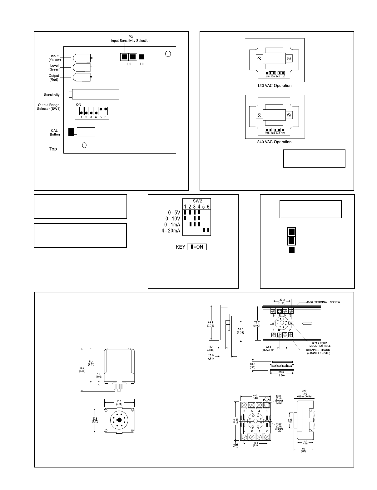
I/O Card Configuration
Top View Diagram
*
Warning: Do not change
with power connected!
Figure 2: I/O Card Factory Calibration: 0 to 1000Hz,
1V peak, 4-20mA (Shown sideways to view switches)
Warning: Do not configure I/O switch
ranges with power on. Damage will result!
Warning: Applying voltage to the
input with W1 in current (I) position
will result in damage to the unit.
Table 1: Output Switch Settings
Accessories
All Action Paks feature plug-in installation. Model AP7380 uses an
8-pin base and either molded socket M008 or DIN socket MD08.
Dimensions
Dimensions are in millimeters (inches)
(SW1, 1 through 6)
Figure 3: 120/240 VAC Selection
Warning: Do not change
with power connected!
LO
HI
150mVp -1Vp,
0.5Vp-10Vp,
P3
Figure 4: Input Sensitivity Settings (P3)
(can reject voltage up to those shown)
Mark II
M008 (Track/Surface)
MD08 (DIN Rail)
Page 4

Specifications
r
Input Ranges (selectable):
Frequency Input:
Full Scale Range: 2 Hz to 10,000Hz
Amplitude Range:
150mVp to 10Vp,150Vrms max
Impedance: >10K Ohms
Over-voltage: 180Vrms, max
Over-range: 20KHz, max.
Common Mode (Input to Ground):
1500VDC, max
Zero Turn-Up:
99% of full scale range (9998Hz)
Span Turn-Down:
99% of full scale range (2Hz)
Output:
Voltage Output:
Output: 0-5V, 0-10V
Impedance: <10 Ohms
Drive: 10mA, max. (1K Ohms, min @10V)
Current Output:
Output: 0-1mA, 4-20mA
Impedance: >100K Ohms
Compliance:
0-1mA; 10V, max.(10K Ohms, max)
4-20mA; 20V, max.(1K Ohms, max)
Accuracy (including Linearity & Hysterisis):
+0.1% of selected range at 25°C.
Stability:
+0.025%/°C maximum of selected range.
Response Time (10-90%):
3 input cycles plus 250mSec
Common Mode Rejection:
DC: 100dB
>60Hz: 80dB
Isolation:
1500VDC between input, output and power.
ESD & Transient Susceptibility:
Meets IEC 801-2, Level 2 (4KV)
LED Indication:
LEVEL (green): lit when power is on
(Intensity varies with input signal);
input > 107% then 8Hz flash
input < -7% then 4Hz flash
INPUT (yellow): input range programming
status
OUTPUT (red): output range programming
status
Humidity (Non-Condensing):
Operating: 15 to 95% (@ 45°C)
Soak: 90% for 24 hours (@ 65°C)
Temperature Range:
Operating: -15 to 60°C (5 to140°F)
Storage: -25 to 70°C (-13 to158°F)
Power:
Consumption:
2W typical, 3W max
Standard:
selectable 120/240VAC, ±10%, 50-60Hz
Weight:
.60lbs
Agency Approvals:
CSA certified per standard C22.2 No. 0-M91
and 142-M1987 (File No. LR42272 - 64).
UL recognized per standard UL508
(File No. E99775)
Ordering Information
Specify:
1. Model: AP7380-0000
2. Option: U, see text
3. Line Power: 120/240VAC
4. C620: Factory Calibration of input range, setpoints and output relays.
(All power supplies are transformer-isolated from the internal circuitry.)
Note: For UL applications above 100V (unrestricted), the signal must be
transient limited (e.g. 150V MOV). For CSA applications above 100V
(unrestricted), the signal must be isolated from the primary by a 150VA
transformer and no fire result from a short circuit at the input.
Accessories:
M801-0000 Retaining Spring
M008-A 8 pin Track Mount Socket
M004-0000 4 ft Long Channel Track
MD08-0000 8 pin DIN Mount Socket
Printed on recycled pape
Action Instruments
Pin Connections
Chessell
1 Power (Hot)
2 Shield (Gnd)
3 Power (Neu)
4 Spare Termination
5 Frequency Input (+)
6 Frequency Input (-)
7 Output (+)
8 Output (-)
721-0543-00-M 09/06 Copyright© Eurotherm, Inc 2006
Eurotherm
 Loading...