

Page 1
AP6380-0000
Action PAK
®
AP6380
Input Isolated, Field Configurable Isolator
Provides a Fully Isolated DC Output
in Proportion to an AC Input
Field Configurable Input Ranges: 50mV to 200V AC,
5mA to 100mA AC
Four Field Configurable Output Ranges: 0-5V, 0-10V,
0-1mA, 4-20mA
Description
The field configurable AP6380 signal conditioner offers wide
ranging input capability for scaling, converting or isolating AC
inputs ranging from 5mA AC to 100mA AC or 50mV AC to 200V
AC. The DC output of the AP6380 is proportional to the average
of the fully-rectified AC input signal, and is calibrated for sine
waves from DC to 1KHz.
For current inputs above 100mA AC, it is recommended that an
input shunt resistor be used and the AP6380 be configured for the
proper input voltage range. For example, for a 5A AC current
transformer output, use the Action model C006 resistor (0.1W,
5W, 1%) and set the input for 0-500mV AC.
Application
The Action Pak AP6380 is useful in applications requiring a
conditioned DC output from an AC source. Typical applications
include energy management, load shedding, motor current/load
monitoring, locked rotor detection, isolation and data acquisition.
The output of the AP6380 can drive a digital meter for direct
display or can interface with alarming or control devices including
PLCs and computers.
Diagnostic LED
Input power and signal status are indicated with a dual-function
LED on the AP6380. The green LED will illuminate when line power
is applied, and will pulse quickly (8 Hz) if the input rises 10% above
the set input full scale range. If this continues to occur, you may
wish to change your full scale input range setting.
Eliminates Ground Loops
Plug-In Installation
Selectable 120/240VAC Input Power
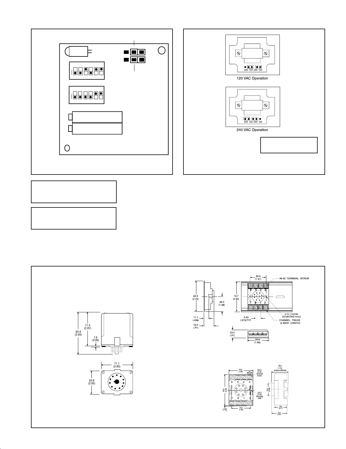
The line power is preset at the factory for 120V AC. This may be
reconfigured by referring to figure 2.
Warning: Do not change switch settings with power applied.
Severe damage may occur!
Calibration
1. Before applying power to the Action Pak, set the DIP switches
inside the Action Pak for your full scale input and full scale output
ranges. Refer to Tables 1, 2 & 3 showing switch configuration
settings.
2. Connect the AC input terminals (5 & 6) to a calibrated AC
voltage or AC current source. Connect a meter to measure the
output (terminals 7 & 8).
3. Connect power to terminals (1 & 3) on the Action Pak and turn
on the power.
4. Wait approximately 1 hour to ensure thermal stability before
calibrating.
5. Set the calibrator to the desired minimum AC input on the
Action Pak. Adjust the “Zero” potentiometer until the DC output
coincides with the desired minimum output.
6. Set the calibrator input to the desired full scale AC input. Adjust
the “Span” potentiometer until the DC output coincides with the
desired full scale output.
Configuration
The AP6380 can be set for a wide variety of full scale input ranges.
The factory pre-sets the AP6380 with an input range of 0-500mV
AC (SW1 & W2) and an output range of 4-20mA DC (SW2) as shown
in Figure 1. For other I/O ranges, remove the four base screws to
access the I/O range configuration selectors.
7. Repeat steps 5 and 6, as necessary, for best accuracy.
Page 2
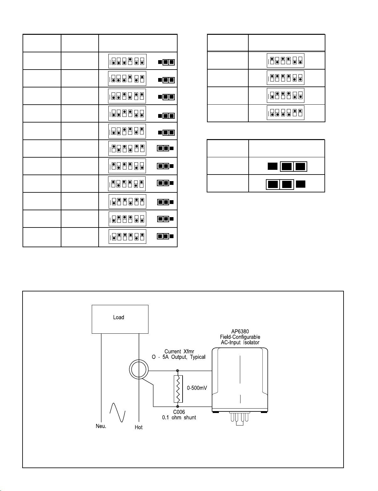
Table 1: Input Range Selector Switch Settings
Table 2: Output Range Selector Switch Settings
Voltage
Span*
Current
Span*
100mV 10mA
200mV 20mA
500mV 50mA
1V 100mA
2V
5V
10V
20V
50V
100V
200V
Input Range Selector
(SW1 & W2)
ON
>
SW1
12 3
4
5
ON
>
123
45
ON
>
23
1
45
ON
>
>
ON
12 3
45
ON
>
ON
>
12 3
4
5
ON
>
23
1
4
5
ON
>
23
1
45
ON
>
23
1
4
5
ON
>
12 3
4
5
Range
W2
6
6
6
0 to 10V
0 to 5V
0 to 1mA
4 to 20mA
6
Table 3: AP6380 Input Jumper Settings
Input
6
6
6
6
6
Voltage
Current
Output Range Selector
(SW2)
ON
>
123
ON
>
1
ON
>
12 3
ON
>
1
5
4
2356
4
5
4
2356
4
6
6
Input Jumper Selector
(W1)
I
V
I
V
*Use jumper (W1) to configure either voltage or current input.
All unipolar ranges are zero based.
Typical Application
Page 3
I/O Card Configuration
Top View Diagram
Current(I)/Voltage(V) Input Selection
Diagnostic
LED
Input Range
Selector
(SW1)
Output Range
Selector
(SW2)
ON
ON
>
>
23
1
123
6
5
4
6
5
4
Span
Zero
Top
Figure 1: I/O card factory settings shown:
0-500mV AC input, 4-20mA output
Warning: Do not configure I/O switch
ranges with power on. Damage will result!
W1
V
I
W2
Input Range Selection
(see table 1)
Warning: Do not change
with power connected!
Figure 2: 120/240 VAC Selection
Warning: Applying voltage to the
input with W1 in current (I) position
will result in damage to the unit.
Mounting
All Action Paks feature plug-in installation. Model AP6380 uses an 8-pin
base, either molded socket (M008) or DIN rail socket (MD08).
Dimensions
Dimensions are in millimeters (inches)
M008 (Track/Surface)
Mark II
MD08 (DIN Rail)
Page 4

Specifications
r
Input Ranges (selectable):
Voltage: 50mV AC to 200V AC
Current: 5mA AC to 100mA AC
Input Frequency:
DC-1KHz, factory calibrated at 60Hz
Input Impedance:
Voltage: >100K Ohms
Current: 20 Ohms typical
Input Overload (without damage):
Voltage: 300V AC
Current: 200mA AC, 60V peak
Common Mode Voltage:
1500V DC, input to ground
Output Ranges (selectable):
Voltage: 0-5V DC, 0-10V DC
Current: 4-20mA DC, 0-1mA DC
Output Source Impedance:
Voltage: <10 Ohms
Current: >100K Ohms
Output Drive:
Voltage: 10mA, max (1K Ohms min. @ 10V)
Current: 20VDC compliance
(1K Ohms max @ 20mA)
Span Turn Down:
50% of full scale range
Zero Turn Up:
50% of full scale range
LED Indication:
8Hz flash when input is 10% above full
scale configuration
Accuracy (including hysteresis and linearity):
±0.1% of span, typical
±0.5% of span, maximum
Response Time:
250mSec, typical
Stability:
±0.025% of full scale per °C, typical
Common Mode Rejection:
120dB, DC to 60Hz
Isolation (input to output to power):
1500V DC or peak AC
Temperature Range:
Operating: 0 to 60°C (32 to 140°F)
Storage: -15 to 70°C (5 to 158°F)
Humidity (Non-Condensing):
10 to 95% RH, at 45°C
Power:
Consumption: 3W typical, 5W max
Standard: Selectable 120/240V AC
(±10%, 50-60Hz)
Weight:
0.60lbs
Agency Approvals:
CSA certified per standard C22.2, No. M1982
(File No. LR42272-38).
UL recognized per standard UL508
(File No. E150323).
Ordering Information
Specify:
1. Model: AP6380-0000.
2. Option U (see text).
3. Line Power (see specs).
4. Optional Factory Calibration (C620):
Specify input range, output range and power.
5. C006 (0.1 Ohm shunt for 1 to 5 Amp current inputs).
Accessories:
M801-0000 Retaining Spring
M008-A 8 pin Track Mount Socket
M004-0000 4 ft Long Channel Track
MD08-0000 8 pin DIN Mount Socket
Printed on recycled pape
Action Instruments
Pin Connections
Chessell
1 AC Power (Hot)
2 Shield (GND)
3 AC Power (Neu)
4 Spare Termination
5 Input
6 Input
7 Output (+)
8 Output (-)
721-0482-00-R 09/06 Copyright© Eurotherm, Inc 2006
Eurotherm
 Loading...