

Page 1
Protecting the
Integrity of
LVDT-Input Signal
Conditioner
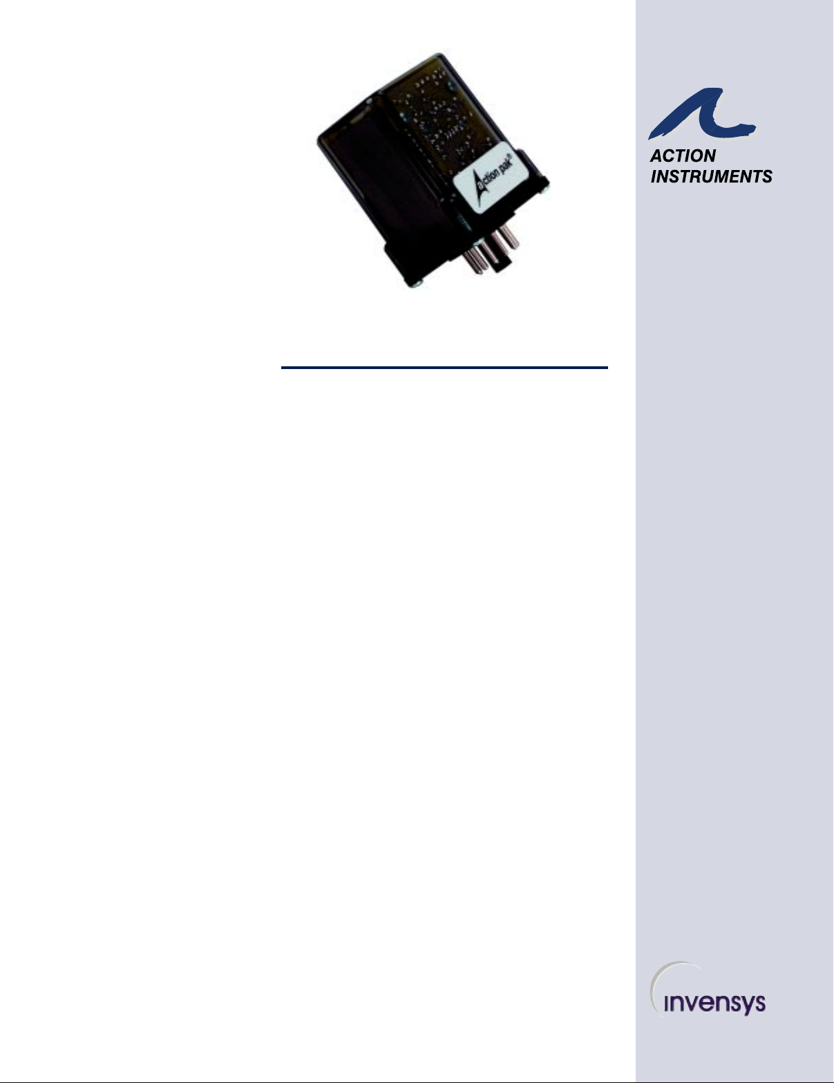
ACTION PAK®AP6050
MODEL
Benefits
! Displacement and Position-
Sensing Applications
! Provides LVDT Excitation
Adjustable from 6-10V p-p
! Easy Plug-In Installation/
Low Mean-Time-to Repair
! AC Line Powered
! Three Year Warranty
Provides a DC Output in Proportion
to an L VDT (Linear V ariable
Differential T ransformer) Input
DESCRIPTION
The AP6050 LVDT Conditioning Module provides synchronous
demodulation and conditioning for Linear Variable Differential
Transformer (LVDT) transducers used in the control, display, and
recording of motion.
The AP6050 LVDT Transmitter provides the AC sine wave
excitation (adjustable from 6-10V p-p nominally 4kHz) for LVDT
operation. The module transmits a DC voltage or current output
proportional to the motion applied to the input transducer.
ZERO AND SPAN
ADJUSTMENTS
Zero and span are factory set, but may be field adjusted (the LVDT
is assumed to be previously calibrated). Zero is adjusted for a zero
output with the LVDT at its mechanical null, or zero displacement
position. Span is adjusted for a full scale output with the LVDT at
its appropriate mechanical extreme, or full displacement position.
Zero and span are each screwdriver adjustable and accessible
through the top cover of the module.
Industrial
Process Signals
EXCITATION ADJUSTMENT
If zero and span adjustments cannot calibrate the output span
appropriate to the LVDT travel input signal, roughly center zero
and span adjustments and set EXC as needed to boost or decrease
the LVDT's full travel signal for zero and span calibration.
OPTION
U Urethane coating of internal circuitry for protection from
corrosive atmospheres
An Invensys Company
Page 2
SPECIFICATIONS
Input (AC p-p) 20mV/V to 1V/V
Input Impedance= >100KΩ
Excitation Adjustable 6-10V p-p (4KHz)
Drives 250Ω @8V p-p
Output Ripple <0.2% of span p-p
Output Impedance Voltage: <10Ω
Current: >100KΩ
Output Drive Voltage Output: 10mA, max (1K Ω, max)
Voltage Output (bipolar): 2mA, max
Current Output: 12V compliance @ 20mA (600 Ω, max)
Adjustments (Zero, Span) Factory-set at zero and full scale, to within 0.5% of
span, typical (adjustment range to 10 % of span to
either side of factory-setting, typical).
Table 1: Standard Inputs
0-20mV/V
0-50mV/V
Table 2: Input Limits
Minimum Span Maximum Input
0-100mV/V
±400mV/V
20mV/V 1V/V
±420mV/V
±500 mV/V
±800mV/V
Table 3: Standard
Outputs
0 to 10V
0 to 1V
0 to 5V
1 to 5V
±5V
Linearity
(Best Straight Line) 0.25% of span, typical
Reponse Time 150mSec, typical
Stability Within 0.05% of span/°C
Common Mode Rejection 60Hz: >80dB
DC: >100dB
Common Mode Voltage 500V DC or peak AC, max
Temperature Range Operating: 0 to 60°C (32 to 140°F)
Storage: -20 to 85°C (-4 to 185°F)
Power Consumption: 3W typical, 5W max
Standard: 120 VAC ( ±10%, 50 - 400Hz)
Available: 240 VAC (±10%, 50 - 400Hz)
Weight 0.60lbs
Table 4: Output Limits
4 to 20 mA
Voltage
Current
Minimum
Span
100mV
1mA
Maximum
Output
10V
50mA
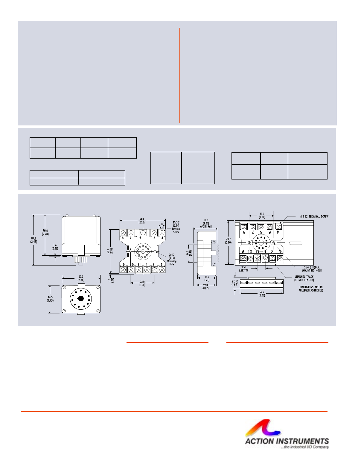
DIMENSIONS
Dimensions are in mm (inches)
MODELS & ACCESSORIES
Mounting
All Action Paks feature plug-in installation. Model
AP6050 uses an 11-pin base using either molded
socket M011 or DIN rail MD11, mounting sockets.
MD11 (DIN/Surface)
Ordering Information
1. Model: AP6050
2. Input Range (see Table 1, 2)
3. Output Range (see Table 3, 4)
4. Option: U (see text)
5. Line Power (see specs)
(All power supplies are transformerisolated from the internal circuitry.)
M011 (Track/Surface)
Pin Connections
1. AC Power (Hot)
2. Shield (Gnd)
3. AC Power (Neu)
4. Input (+)
5. Input (-)
6. Not used
7. Excitation (+)
8. Excitation (-)
9. Output (+)
10. Output (-)
11. Not used
721-0476-00-H 1/08
 Loading...