

EuroTel ETL0W474G Operating And Technical Manual
Rev. 004 ETL0W474G
Operating and Technical Manual
Operating and Technical ManualOperating and Technical Manual
Operating and Technical Manual
ETL0W474G
ETL0W474GETL0W474G
ETL0W474G
750 W (RMS) DTV / 1800 W ATV
750 W (RMS) DTV / 1800 W ATV750 W (RMS) DTV / 1800 W ATV
750 W (RMS) DTV / 1800 W ATV
UHF B IV-V RF LIQUID-COOLED POWER AMPLIFIER
UHF B IV-V RF LIQUID-COOLED POWER AMPLIFIER UHF B IV-V RF LIQUID-COOLED POWER AMPLIFIER
UHF B IV-V RF LIQUID-COOLED POWER AMPLIFIER
EuroTel S.p.A.
Via Martiri della Libertà, 4
20035 Lissone (MI), Italy
Tel. +39 039 24361 – Fax +39 039 2436222
E-Mail sales@eurotel.it – Web http://www.eurotel.it
Oct 2013 CMAN0W474G Page 1111

ETL0W474G Rev. 004
Page 2 CMAN0W474G Oct 2013

Rev. 004 ETL0W474G
Operating and Technical Manual
Operating and Technical ManualOperating and Technical Manual
Operating and Technical Manual
750 W (RMS) DTV / 1800 W ATV
750 W (RMS) DTV / 1800 W ATV750 W (RMS) DTV / 1800 W ATV
750 W (RMS) DTV / 1800 W ATV
UHF B IV-V RF LIQUID-COOLED POWER AMPLIFIER ETL0W474G
UHF B IV-V RF LIQUID-COOLED POWER AMPLIFIER ETL0W474GUHF B IV-V RF LIQUID-COOLED POWER AMPLIFIER ETL0W474G
UHF B IV-V RF LIQUID-COOLED POWER AMPLIFIER ETL0W474G
TABLE OF CONTENTS
TABLE OF CONTENTSTABLE OF CONTENTS
TABLE OF CONTENTS
Section A- GENERAL INFORMATION..............................................................................................5
I - AMENDMENT RECORD SHEET............................................................................................5
II - APPROVAL RECORD SHEET................................................................................................5
Section B- SAFETY INSTRUCTIONS...............................................................................................6
1 ) GENERAL INSTRUCTIONS...........................................................................................6
2 ) A.C. LINE HAZARDS....................................................................................................6
3 ) R.F. HAZARDS.............................................................................................................7
4 ) FIRE RISK....................................................................................................................7
5 ) HANDLING BERYLLIUM OXIDE CERAMICS..................................................................7
6 ) FIRST AID PROCEDURES IN CASE OF ELECTRIC SHOCK..............................................7
7 ) EMERGENCY RESUSCITATION: EXPIRED AIR METHOD................................................8
8 ) TREATMENT FOR BURNS.............................................................................................8
Section C- SYSTEM DESCRIPTION AND TECHNICAL SPECIFICATIONS...................................9
I - INTRODUCTION................................................................................................................9
II - COMPOSITION OF RF AMPLIFIER SERIES ETL0W474G.......................................................9
III - TECHNICAL SPECIFICATIONS...........................................................................................10
1 ) General......................................................................................................................10
2 ) Input Parameters.........................................................................................................10
3 ) Output Parameters......................................................................................................10
4 ) Dimensions and Weight..............................................................................................10
IV - FUNCTIONAL DESCRIPTION.............................................................................................11
1 ) Theory of operation of UHF RF Amplifier ETL0W474G series.........................................11
Section D- INSTALLATION AND OPERATING INFORMATION.....................................................13
I - INSTALLATION...................................................................................................................13
1 ) Series ETL0W474G R. F. Amplifier: mounting procedure...............................................13
2 ) Other connections.......................................................................................................13
3 ) Series ETL0W474G: front panel controls, displays & connectors ...................................14
4 ) Series ETL0W474G: rear panel connectors...................................................................16
5 ) Enable IN/OUT DIN socket..........................................................................................18
6 ) ALARMS OUT socket...................................................................................................18
7 ) SERIAL DATA RS-485 socket........................................................................................19
8 ) SERIAL PORT RS-232 socket.........................................................................................19
9 ) E-LINK SERIAL NETWORK socket..................................................................................19
10 ) Data Communication................................................................................................20
Oct 2013 CMAN0W474G Page 3333

ETL0W474G Rev. 004
II - OPERATING PROCEDURES.................................................................................................21
1 ) First time operation of series ETL0W474G....................................................................21
2 ) ETL0W474G: changing the M.L.C. Nominal value........................................................22
3 ) RF Amplifier series ETL0W474G: in case of difficulty.....................................................23
III - SERIES ETL0W474G - MULTI-FUNCTION METERING DISPLAY............................................24
1 ) Alphanumeric LCD display description.........................................................................24
2 ) First level menu description..........................................................................................25
3 ) Second level menu description.....................................................................................28
4 ) Alarm and Warning Events..........................................................................................32
5 ) Warning LED..............................................................................................................33
Section E- LAYOUT ASSEMBLY AND CIRCUIT DIAGRAMS.........................................................35
I - MAINFRAME.......................................................................................................................35
1 ) ETL0W474G Layout of R.F. parts of Amplifier...............................................................35
TABLE OF ILLUSTRATIONS
TABLE OF ILLUSTRATIONSTABLE OF ILLUSTRATIONS
TABLE OF ILLUSTRATIONS
Figure 1: UHF TV RF Power Amplifier series ETL0W474G, blocks diagram...............................12
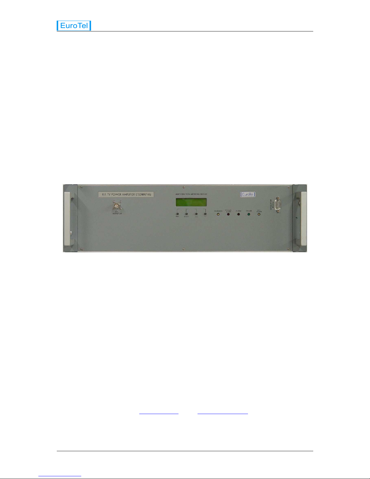
Figure 2: Front panel of series ETLW0474G TV RF Amplifier......................................................15
Figure 3: Rear panel of series ETL0W474G TV RF Amplifier........................................................17
Figure 4: Enable socket and connector..........................................................................................18
Figure 5: ALARMS OUT socket........................................................................................................18
Figure 6: Serial DataRS485 in-out socket......................................................................................19
Figure 7: Serial Data Com in-out socket.........................................................................................19
Figure 8: E-LINK SERIAL NETWORK in-out socket.......................................................................19
Figure 9: Example of PC's display for RS-232 connection...........................................................32
Page 4 CMAN0W474G Oct 2013
Rev. 004 ETL0W474G
Section A-
Section A-Section A-
Section A-GENERAL INFORMATION
GENERAL INFORMATIONGENERAL INFORMATION
GENERAL INFORMATION
I -
I - I -
I - AMENDMENT RECORD SHEET
AMENDMENT RECORD SHEETAMENDMENT RECORD SHEET
AMENDMENT RECORD SHEET
When an amendment to this publication is incorporated, the record below is to be completed and
initialed.
Release
ReleaseRelease
Release
Language
LanguageLanguage
Language
DESCRIPTION
DESCRIPTIONDESCRIPTION
DESCRIPTION
AUTHORITY
AUTHORITYAUTHORITY
AUTHORITY
DATE
DATEDATE
DATE
II -
II - II -
II - APPROVAL RECORD SHEET
APPROVAL RECORD SHEETAPPROVAL RECORD SHEET
APPROVAL RECORD SHEET
When an approval to this publication is incorporated, the record below is to be completed.
Release
ReleaseRelease
Release Signature
SignatureSignature
Signature AUTHORITY
AUTHORITYAUTHORITY
AUTHORITY DATE
DATEDATE
DATE
© EUROTEL S.p.A.
© EUROTEL S.p.A.© EUROTEL S.p.A.
© EUROTEL S.p.A.
The information contained herein is the property of EUROTEL S.p.A. and is supplied without liability
The information contained herein is the property of EUROTEL S.p.A. and is supplied without liability The information contained herein is the property of EUROTEL S.p.A. and is supplied without liability
The information contained herein is the property of EUROTEL S.p.A. and is supplied without liability
for errors or omissions and no part may be reproduced, used or disclosed, except as authorized by
for errors or omissions and no part may be reproduced, used or disclosed, except as authorized by for errors or omissions and no part may be reproduced, used or disclosed, except as authorized by
for errors or omissions and no part may be reproduced, used or disclosed, except as authorized by
contract or other written permission. The copyright and the foregoing restriction on reproduction, use
contract or other written permission. The copyright and the foregoing restriction on reproduction, use contract or other written permission. The copyright and the foregoing restriction on reproduction, use
contract or other written permission. The copyright and the foregoing restriction on reproduction, use
and disclosure extends to all media in which this information may be embodied, including magnetic
and disclosure extends to all media in which this information may be embodied, including magnetic and disclosure extends to all media in which this information may be embodied, including magnetic
and disclosure extends to all media in which this information may be embodied, including magnetic
or electronic storage, etc.
or electronic storage, etc.or electronic storage, etc.
or electronic storage, etc.
Oct 2013 CMAN0W474G Page 5555

ETL0W474G Rev. 004
Section B-
Section B-Section B-
Section B-SAFETY INSTRUCTIONS
SAFETY INSTRUCTIONSSAFETY INSTRUCTIONS
SAFETY INSTRUCTIONS
1 )
1 ) 1 )
1 ) GENERAL INSTRUCTIONS
GENERAL INSTRUCTIONSGENERAL INSTRUCTIONS
GENERAL INSTRUCTIONS
Observe the following safety precautions when handling this unit. This equipment operates with
dangerous voltages and currents.
• All electrical installations and connections are to be carried out only by skilled personnel.
• When outfitting operating rooms as well as setting up and operating electrical equipment follow the
relevant national and international safety instructions and regulation.
• When setting up the rack observe the relevant safety precautions for the prevention of accidents.
These precautions especially relate to: danger of getting crushed when working with loads, danger
of falling off ladders while working, danger of getting hurt or injured when lifting heavy loads.
• Always disconnect power before opening covers or removing any part or module of this amplifier
unit.
• Prior to checking out or working on the switch mode supply, disconnect all the R.F. power
amplifiers.
• Some of the R.F. power amplifier transistors are encased in Beryllium Oxide (BeO). This substance
is harmless as is, but becomes very dangerous if ground to a powder. These devices, once failed,
cannot be disposed of by normal means and special procedures of disposal must be observed.
• In any case, but especially when the R.F. Power Amplifier is operating,
In any case, but especially when the R.F. Power Amplifier is operating, In any case, but especially when the R.F. Power Amplifier is operating,
In any case, but especially when the R.F. Power Amplifier is operating, do not attempt
do not attemptdo not attempt
do not attempt to remove
to remove to remove
to remove
and then re-insert the rear panel coaxial interconnecting cables of the EXCITER. Although
and then re-insert the rear panel coaxial interconnecting cables of the EXCITER. Although and then re-insert the rear panel coaxial interconnecting cables of the EXCITER. Although
and then re-insert the rear panel coaxial interconnecting cables of the EXCITER. Although
suitable protection circuitry is in place, sudden loss and re-application of R.F. drive causes
suitable protection circuitry is in place, sudden loss and re-application of R.F. drive causes suitable protection circuitry is in place, sudden loss and re-application of R.F. drive causes
suitable protection circuitry is in place, sudden loss and re-application of R.F. drive causes
transients that may damage one or more R.F. amplification stages.
transients that may damage one or more R.F. amplification stages.transients that may damage one or more R.F. amplification stages.
transients that may damage one or more R.F. amplification stages.
2 )
2 ) 2 )
2 ) A.C. LINE HAZARDS
A.C. LINE HAZARDSA.C. LINE HAZARDS
A.C. LINE HAZARDS
Voltage values Vrms > 30V A.C. or V > 60V D.C. are potential hazard. Take appropriate measures to
avoid any danger when working with hazardous voltages.
Never work on live parts. It is only permissible to work on live parts under exceptional circumstance and
if special safety precautions have been taken.
Power Supply
Power SupplyPower Supply
Power Supply
Prior to connecting power supply ensure that the A.C. line data on the product matches the data of the
available supply. Fuses or other devices in the supply circuit must guarantee overload and short-circuit
protection.
The user is responsible for correct fuse protection.
Page 6 CMAN0W474G Oct 2013

Rev. 004 ETL0W474G
3 )
3 ) 3 )
3 ) R.F. HAZARDS
R.F. HAZARDSR.F. HAZARDS
R.F. HAZARDS
In the amplifier, high-energy R.F. circuits are fed through common R.F. connectors (eg N). Depending
on the output power, the amplifier outputs are fitted with screw-in R.F. lines or waveguides.
CAUTION!
CAUTION!CAUTION!
CAUTION!
1. Never unscrew R.F. lines when the amplifier is in operation.
2. Never open the module when the amplifier is in operation.
If R.F. lines which are in operation are disconnected, electric arcs may be generated and cause burns
and eye injuries.
3. Never put the amplifier into operation when R.F. lines are open-circuited.
4 )
4 ) 4 )
4 ) FIRE RISK
FIRE RISKFIRE RISK
FIRE RISK
There is a risk of fire presented by any live electrical if there is sufficient energy conversion which is the
case with radio transmitters.
Preventive measures on-site can reduce fire hazards to a large extent and effectively reduce the fire
spreading.
CAUTION!
CAUTION!CAUTION!
CAUTION!
• On installing the transmitter, the user shall ensure that no combustible materials are store ro fitted
beneath or above the cable entry.
Firefighting must be performed only with special equipment (eg breathing apparatus with air bottle) in
order to avoid inhalation of harmful fumes, gases and dust produced by combustion.
5 )
5 ) 5 )
5 ) HANDLING BERYLLIUM OXIDE CERAMICS
HANDLING BERYLLIUM OXIDE CERAMICSHANDLING BERYLLIUM OXIDE CERAMICS
HANDLING BERYLLIUM OXIDE CERAMICS
Parts containing BeO ceramics are not a health hazard provided that safety regulations are followed.
CAUTION!
CAUTION!CAUTION!
CAUTION!
Parts made from BeO ceramics shall not be machined, scored, crushed, broken, heated nor
sandblasted. BeO dust passes through all common filtering system including conventional apparatus
filters.
Parts made from BeO ceramics shall not be opened nor destroyed.
6 )
6 ) 6 )
6 ) FIRST AID PROCEDURES IN CASE OF ELECTRIC SHOCK
FIRST AID PROCEDURES IN CASE OF ELECTRIC SHOCKFIRST AID PROCEDURES IN CASE OF ELECTRIC SHOCK
FIRST AID PROCEDURES IN CASE OF ELECTRIC SHOCK
DO NOT TOUCH THE VICTIM WITH YOUR BARE HANDS UNTIL THE ELECTRICAL CIRCUIT IS BROKEN.
SWITCH OFF. If this is not possible, PROTECT YOURSELF with DRY insulating material and pull the
victim clear of the conductor. If breathing has stopped indicated by UNCONSCIOUSNESS, LACK OF
RESPIRATORY MOVEMENTS and a “BLUE “ LOOK to CHEEKS, LIPS, EARS and NAILS, START
RESUSCITATION AT ONCE, as directed below.
Oct 2013 CMAN0W474G Page 7777
ETL0W474G Rev. 004
7 )
7 ) 7 )
7 ) EMERGENCY RESUSCITATION: EXPIRED AIR METHOD
EMERGENCY RESUSCITATION: EXPIRED AIR METHODEMERGENCY RESUSCITATION: EXPIRED AIR METHOD
EMERGENCY RESUSCITATION: EXPIRED AIR METHOD
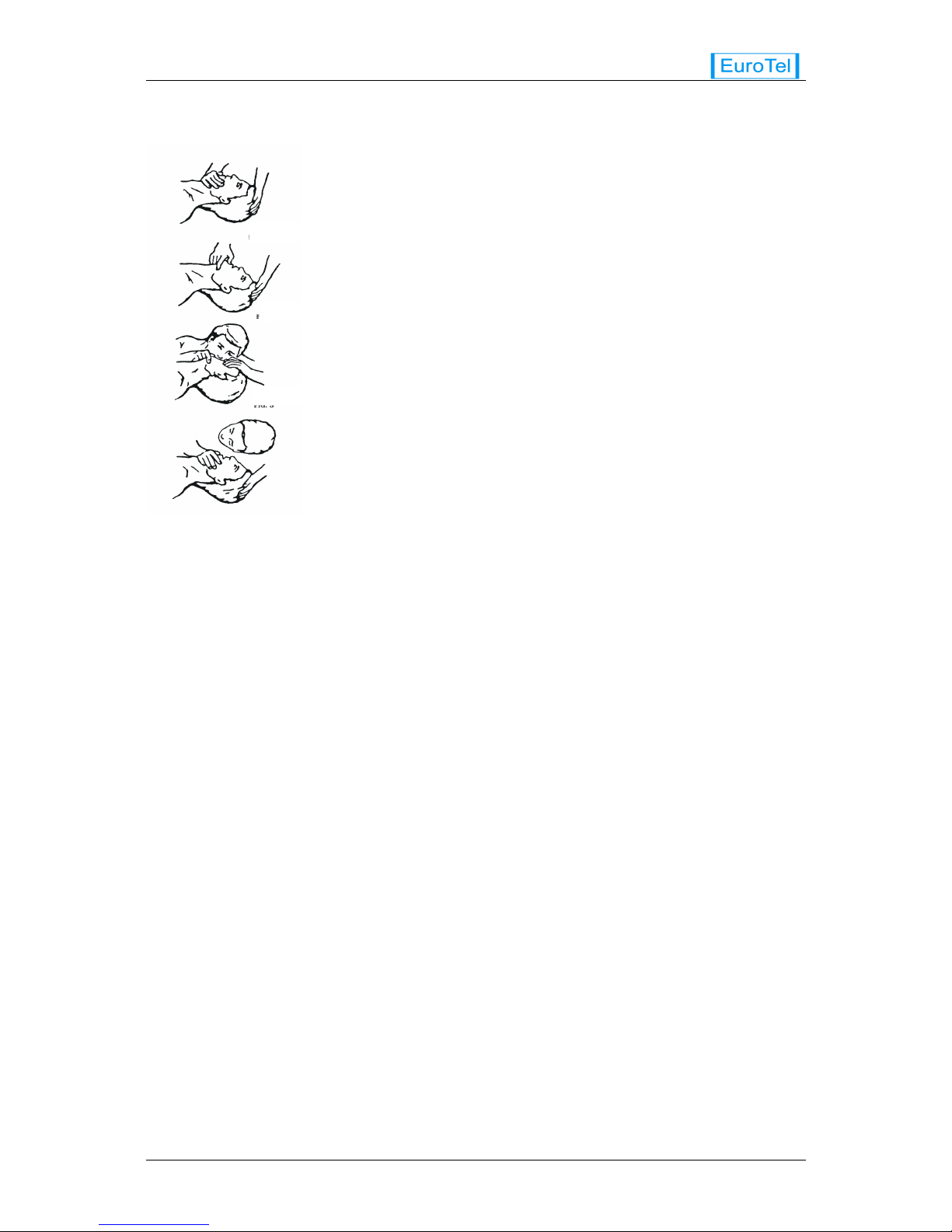
If possible, lie the victim on his back, with his head slightly higher than
his feet. Clear the mouth and the throat of any obvious obstruction.
Kneel on one side of the victim, level with his head. LIFT THE JAW AND
TILT THE HEAD BACK AS FAR AS POSSIBLE. Figures 1 and 2.
One of the following may now happen:
One of the following may now happen:One of the following may now happen:
One of the following may now happen:
• Breathing may begin and consciousness return.
• Breathing may begin, but consciousness may NOT RETURN. Turn
the victim on his side and ensure that the airways are kept clear.
• Breathing may begin, but be NOISY, which means that the airways
are not fully clear. Try to clear the airways.
If there is no sign of breathing:
If there is no sign of breathing:If there is no sign of breathing:
If there is no sign of breathing:
• Check that the head is still tilted back.
• Take a deep breath.
• Pinch the victim’s nose and (Figure. 3) blow firmly into his mouth.
As you do, his chest will RISE.
• Turn your head away and take another breath, watching for his
chest to FALL (Figure. 4).
• Start with four quick deep breaths and then continue with one breath every five seconds (i.e. 12
times a minute). This should be continued until the victim revives or a doctor certifies death.
• As consciousness returns, the victim will start to breathe on his own and a “PINK” colour will
replace the “BLUE” look. This is the time to stop resuscitation. Continue to hold his chin up so to
keep the airways clear.In the case of injuries to the mouth
injuries to the mouth injuries to the mouth
injuries to the mouth, it may be necessary to use mouth-to
mouth-to mouth-to
mouth-to
nose
nose nose
nose resuscitation. Seal the victim’s mouth with your cheek and blow firmly into his nose,
proceeding as above. In any case IT IS ESSENTIAL TO COMMENCE RESUSCITATION WITHOUT
DELAY and TO SEND FOR MEDICAL ASSISTANCE IMMEDIATELY.
8 )
8 ) 8 )
8 ) TREATMENT FOR BURNS
TREATMENT FOR BURNSTREATMENT FOR BURNS
TREATMENT FOR BURNS
If the victim is also suffering from burns, then, without hindrance to resuscitation, observe the following:
• DO NOT ATTEMPT TO REMOVE CLOTHING ADHERING TO THE BURNS.
• If possible, alleviate the pain from the burnt part by immersing in cold water.
• If help is available, or as soon as resuscitation is no longer required, the wounds should be covered
with a DRY clean dressing.
• Oil and/or grease, in any form, SHOULD NOT be applied. If severely burnt, get the victim to
hospital immediately.
Page 8 CMAN0W474G Oct 2013
Figure 3
Figure 4
Figure 2
Figure 1

Rev. 004 ETL0W474G
Section C-
Section C-Section C-
Section C-SYSTEM DESCRIPTION AND TECHNICAL
SYSTEM DESCRIPTION AND TECHNICAL SYSTEM DESCRIPTION AND TECHNICAL
SYSTEM DESCRIPTION AND TECHNICAL
SPECIFICATIONS
SPECIFICATIONSSPECIFICATIONS
SPECIFICATIONS
I -
I - I -
I - INTRODUCTION
INTRODUCTIONINTRODUCTION
INTRODUCTION
• The series ETL0W474G TV RF Amplifier provides linear, class “AB” amplification of RF TV signal in
the standard UHF bands IV & V (470 to 860 MHz).
• ETL0W474G is designed to work both in DTV mode and ATV mode.
• Rated RF output power is set to 750 W (rms) for DTV mode and 1800 W peak sync for ATV mode.
• The use of high efficiency, high power gain LDMOS power transistors allows to obtain highly
efficient amplifier modules as ETL0W474G.
• The ETL0W474G Amplifier is liquid-cooled. A cooling serpentine routed through the heat-sink
optimally cools the power transistors and the switching power supply unit greatly reducing the
temperature of active elements. This involves an efficiently use and a longer lifetime of the system.
• An additional fan is included in the case of ETL0W474G to create an airflow within the case to
dissipate any residual heat.
• ETL0W474G connection to the cooling system is made through quick couplers at the coolant inlet
and outlet.
II -
II - II -
II - COMPOSITION OF RF AMPLIFIER SERIES ETL0W474G
COMPOSITION OF RF AMPLIFIER SERIES ETL0W474G COMPOSITION OF RF AMPLIFIER SERIES ETL0W474G
COMPOSITION OF RF AMPLIFIER SERIES ETL0W474G
• The series ETL0W474G TV R.F. Amplifier consists of one class “AB” driver stage, that feeds four
class “AB” final RF amplifiers combined. Other parts of this Amplifier are: four identical switching
power supply modules for final amplifiers, two identical switching power supply modules for driver
amplifier, a microprocessor controlled metering, alarm and protection module, a directional
coupler. All these parts are assembled into a standard 3 unit 19 inch rack chassis.
• The four R.F. amplifier modules of the output stage are coupled together by means of three
suspended substrate hybrid couplers.
• The R.F. amplifier modules and the switching power supply of the driver are mounted on a heat sink
in the upper part of the cabinet whereas the other switching power supplies are mounted at the
bottom of the cabinet.
• The modules are:
PARTS SUPPLIED IN THE STANDARD CONFIGURATION
PARTS SUPPLIED IN THE STANDARD CONFIGURATIONPARTS SUPPLIED IN THE STANDARD CONFIGURATION
PARTS SUPPLIED IN THE STANDARD CONFIGURATION QTY
QTYQTY
QTY MODEL
MODELMODEL
MODEL
Class “AB” UHF RF driver Amplifier module 1 MOE267
Class “AB” UHF RF final Amplifier module (4 final Amplifiers) 4 MOE272
Switch Mode Power Supply Unit for driver Amplifiers 2 MOE143-3
Switch Mode Power Supply Unit for final Amplifiers 4 MOE104
Metering, alarm and protection module 1 MOE183-7
Oct 2013 CMAN0W474G Page 9999

ETL0W474G Rev. 004
III -
III - III -
III - TECHNICAL SPECIFICATIONS
TECHNICAL SPECIFICATIONSTECHNICAL SPECIFICATIONS
TECHNICAL SPECIFICATIONS
1 )
1 ) 1 )
1 ) General
GeneralGeneral
General
Primary power 57 V Tri-phase ±15%. Frequency: 47 to 60 Hz
Consumption (channel frequency 800 MHz):
ATV 3800 W @ 50% A.P.L. at 1800 W sync peak power.
DTV 3700 W @ 820 W power out.
Cooling Liquid
Operating temperature range -5°C to +45°C
Storage temperature range -10 to +70°C
Coolant inlet temperature < 55 °C
2 )
2 ) 2 )
2 ) Input Parameters
Input ParametersInput Parameters
Input Parameters
Input R.F. nominal level DTV 0,3 W (rms)
ATV 1 W peak sync
Input impedance
50 Ω, unbalanced
Input return loss < 18 dB
3 )
3 ) 3 )
3 ) Output Parameters
Output ParametersOutput Parameters
Output Parameters
Output frequency range BANDS IV-V: 470-860 MHz
Power gain > 35 dB
Output impedance
50 Ω, unbalanced
Permissible VSWR <1.5
Nominal Output power DTV 750 W (rms)
ATV 1800 W peak sync
4 )
4 ) 4 )
4 ) Dimensions and Weight
Dimensions and WeightDimensions and Weight
Dimensions and Weight
Dimensions Standard 19” frame, 435W x 505D x 135H mm
Weight 23 kg
Page 10 CMAN0W474G Oct 2013

Rev. 004 ETL0W474G
IV -
IV - IV -
IV - FUNCTIONAL DESCRIPTION
FUNCTIONAL DESCRIPTIONFUNCTIONAL DESCRIPTION
FUNCTIONAL DESCRIPTION
1 )
1 ) 1 )
1 ) Theory of operation of UHF RF Amplifier ETL0W474G series
Theory of operation of UHF RF Amplifier ETL0W474G seriesTheory of operation of UHF RF Amplifier ETL0W474G series
Theory of operation of UHF RF Amplifier ETL0W474G series
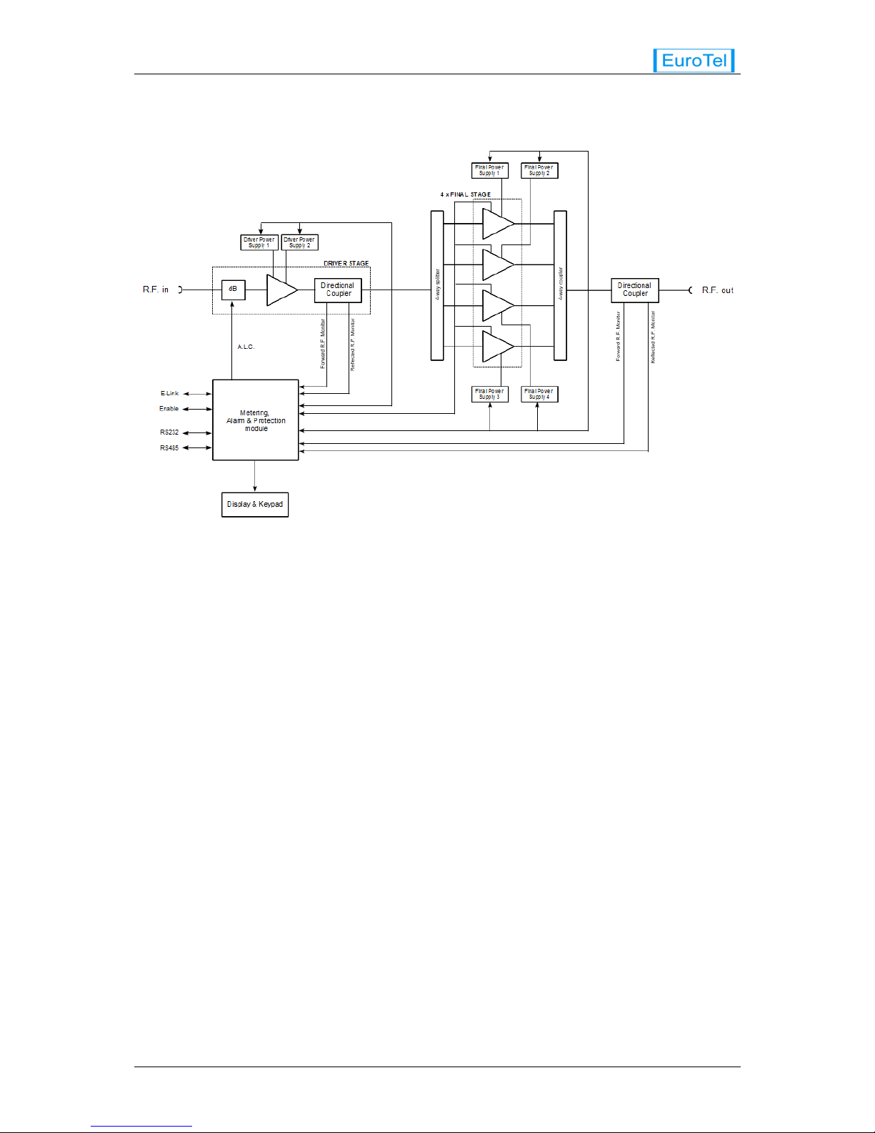
• The series ETL0W474G UHF TV RF Amplifier blocks diagram is shown in Figure 1.
• The nominal RF input coming from the external Exciter is pre-amplified by the driver module
MOE267. An electronic attenuator is mounted at the input of the driver amplifier. The MLC signal
coming from Logic & Microprocessor board controls the attenuator, in order to equalize the gain of
the modular amplifiers of the system.
• On module ETL0W474G an ALC control signal manages the output power of the amplifier in order
to keep constant its value. This ALC reference level is set directly on the module via the control
button on the front panel. When the transmitter system has more than one ETL0W474G Amplifier,
the ALC reference is provided by the Supervisor.
• A directional coupler monitors forward input power sent to the final stage. D.C. samples of these
quantities are sent to the metering, alarm and protection module.
A four way hybrid divider splits the drive power into four components, which feed four modules
MOE272. RF output from each module is combined by a four way hybrid combiner.
The output directional coupler, which is equipped with built-in high sensitivity detectors for forward
and reflected RF power, provides D.C. samples to the Metering and Protection module.
• The metering outputs of the metering, alarm and protection module feed an alphanumeric display,
located on the front panel. This display provides all the significant electrical parameters: RF power,
temperature, supply voltages and currents and other important information.
• The D.C. supply is distributed in such a way that, if one of the power supplies fails, the driver
Amplifier and 3 of the output stages are still supplied. In this condition, the surviving supplies will
sustain an output current increase of several Amperes and the amplifier output will drop to
approximately 50% rated power, but service will not be disrupted. In this situation a warning event is
also generated. If two of the power supplies fail, an alarm event is generated. (See also chapter:
Alarm and warning events).
• Should a transistor of the RF driver stage fail in short circuit, one of the fuses of the D.C. combiner-
splitter circuit will open, and the amplifier output will drop to approximately 25% rated power.
• The yellow LINE LED, when lit, shows presence of A.C. power mains.
• The green ON AIR LED is on when the Amplifier is operating under normal conditions. When the RF
power output drops below approximately half power (- 3 dB threshold), this LED is extinguished. This
led blinks if the amplifier is enable and ready.
• The red ALARM LED is normally dark. It turns on to indicate that one alarm has occurred. In this
condition the Metering, alarm and Protection module immediately disables the amplifier.
• The red V.S.W.R. ALARM LED is normally dark. It turns on to indicate that the reflected output power
has risen above a pre-set, critical threshold. In this condition the Metering and Protection module
immediately disables the amplifier.
• The yellow WARNING LED is normally dark. It turns on to indicate that one or more operating
parameters have risen above the normal limiting values. This LED blinks if some past warnings and
alarms are stored in the EEPROM non volatile memory of the microprocessor. This LED turns off only
if the memory has been cleared.
Oct 2013 CMAN0W474G Page 11
1111
11
ETL0W474G Rev. 004
Figure 1: UHF TV RF Power Amplifier series ETL0W474G, blocks diagram
Page 12 CMAN0W474G Oct 2013
 Loading...