

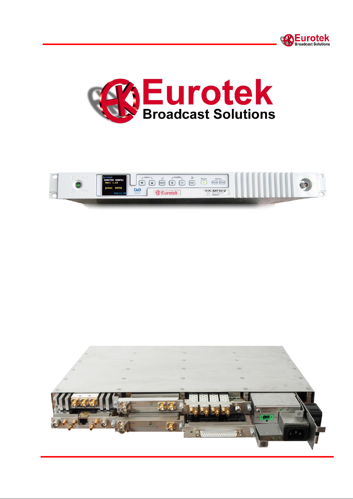
Eurotek EK-MFR/2 User Manual
1
601-000147 Rev. Y
Arch. 5105
25/02/2016
User Manual
System ALL4DIGIT
EK-MFR/2

2
EK-MFR/2
25/02/2016
Arch.5105
601-000147/MN Rev. Y
The present design is property of Eurotek s.r.l. and is protected by Copyright.
Its reproduction, distribution and disclosure to third-parties without written authorisation is forbidden
Every reproduction, re-distribution or disclosure without prior written authorisation
is expressly forbidden by the law and can lead to serious civil and penal sanctions.

3
601-000147 Rev. Y
Arch. 5105
25/02/2016
Warning!
The socket utilized for the unit supply must have the appropriate ground conductor.
The connection of the unit , to a socket without the ground conductor, will make the whole
equipment dangerous for people safety.
About the repairing of the units please refer to specialized personnel only .
Inside the devices there are voltages which could be dangerous to people.
Before opening the cover switch off the unit, disconnect the connection and
the supply cables.
In case of electrical shock please follow the instructions
of first aid listed on page 4
Substitute the fuses interrupted with others of the same type and voltage.
The waste disposal of the devices must be executed in the respect of the enforced laws in
the country uses.
Eurotek not assumed responsibility for waste disposal in contrast with enforced laws.
LIFE SUPPORT APPLICATIONS.
Eurotek’s products are not designed for use as critical components in life support devices or system
without the express written approval of the Eurotek S.r.l. As used herein.
- Life support devices or system are devices or system which, (a) are intended for surgical
implant into the body, or (b) support or sustain life, and whose failure to perform, when
properly used in accordance with instructions for use provided in the labeling, can be
reasonably expected to result in a significant injury to the user.
- A critical component is any component of a life support device or system whose failure to
perform can be reasonably expected to cause the failure of the life support device or system,
or to affect its safety or effectiveness.
The information given in this documentation could have variations without forewarning.
The firm Eurotek S.r.l. does not give any guaranty about this documentation.
The firm Eurotek S.r.l. does not consider itself responsible for possible mistakes which could be
found in this documentation.
4
EK-MFR/2
25/02/2016
Arch.5105
601-000147/MN Rev. Y
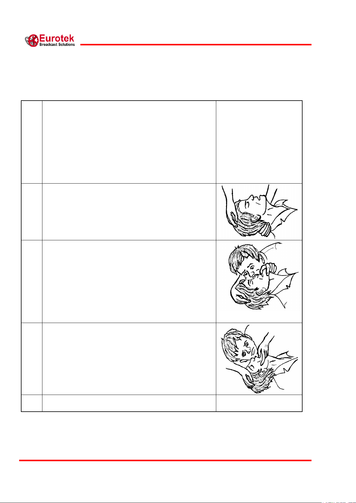
1
In case of electric shock you have to ensure the first aids to
the patient, but to do this you have to consider two very
important things:
- interrupt immediately the electric circuit;
- if the circuit has not been interrupted, do not touch
the patient with bare hands;
After doing this, without delay contact the nearest mobile
unit of first aid and practice to the patient, in case of loss of
consciousness, the breathing mouth to mouth as described
below.
2
Put the patient lying on his back with the arms parallel to
the body, ensure that he does not have the breathing tracts
obstructed (chewing-gum, dental prosthesis, etc.),
otherwise set him free from foreign bodies.
Kneel near the patient‟s head and putting a hand under his
neck, incline as possible his/her head backwards.
3
Going on with keeping the patient‟s head inclined with one
hand, use the other one to occlude the nostrils, if you are
going to practise the breathing through the oral cavity, or
occlude the mouth if you want to do it through the nasal
cavity.
While doing this begin the auto-oxygenation, with deep
breathing.
Then practice the artificial breathing blowing in the chosen
cavity beginning with ten expirations each minute to go on
them with twelve and fifteen.
4
During the breathing procedure you have to control that the
patient‟s chest dilates, otherwise change cavity where to
blow the air because the previous one could be obstructed.
5
Do not ever stop the artificial breathing until the patient
has recovered or the first aid unit has come.
First aid: artificial breathing(mouth to mouth)

5
601-000147 Rev. Y
Arch. 5105
25/02/2016
INDEX
INDEX ..................................................................................................................................................... 5
ABBREVIATIONS .............................................................................................................................. 7
1. GENERAL DESCRIPTION ....................................................................................................... 8
1.1 EK-MFR/2 BLOCK SCHEME .................................................................................................... 9
2. FRONT PANEL ......................................................................................................................... 10
2.1 FRONT PANEL VIEW .............................................................................................................. 10
2.2 FRONT PANEL DESCRIPTION ................................................................................................. 10
3. REAR PANEL ............................................................................................................................ 11
3.1 REAR PANEL VIEW ................................................................................................................ 11
3.2 REAR PANEL DESCRIPTION .................................................................................................... 11
4. DISPLAY AND KEYBOARD .................................................................................................. 12
4.1 DISPLAY AND KEYBOARD DESCRIPTION ................................................................................ 12
5. EK-MFR/2 MENU ..................................................................................................................... 14
5.1 MENU REPRESENTATION ....................................................................................................... 14
5.2 MENU DESCRIPTION AND KEYBOARD GUIDE ......................................................................... 15
5.3 TEMPERATURE CONTROL ...................................................................................................... 33
6. LEDS AND ALARMS ............................................................................................................... 33
6.1 LED DESCRIPTION ................................................................................................................. 33
6.2 ALARMS DESCRIPTION .......................................................................................................... 34
7. OPERATING SYSTEM ............................................................................................................ 35
7.1 OPERATING SYSTEM CONNECTION ........................................................................................ 35
7.2 OPERATING SYSTEM COMMAND ............................................................................................ 35
7.2.1 Read_log ...................................................................................................................... 35
7.2.2 Erase_log ..................................................................................................................... 36
7.2.3 Passwd ......................................................................................................................... 36
7.2.4 Exit ............................................................................................................................... 37
8. AIR FLOW CONSIDERATION .............................................................................................. 38
9. WEB INTERFACE .................................................................................................................... 38
APPENDIX A ..................................................................................................................................... 40
EK-MFR/2 ELECTRICAL INTERFACE ................................................................................................. 40
APPENDIX B ..................................................................................................................................... 41
APPENDIX C ..................................................................................................................................... 42
RS-232 SETTINGS.............................................................................................................................. 41
IF CONNECTION ................................................................................................................................. 42

6
EK-MFR/2
25/02/2016
Arch.5105
601-000147/MN Rev. Y
APPENDIX D ..................................................................................................................................... 43
SNMP – VIRTUAL SLOT .................................................................................................................... 43
APPENDIX E ..................................................................................................................................... 46
EK-MFR/2 POWER SUPPLY SOLUTIONS ............................................................................................. 46
EXAMPLE OF MODULE EXTRACTION .................................................................................................. 47
APPENDIX F ...................................................................................................................................... 49
EK-PWS/A, EK-PWS/C E EK-PWS/D POWER SUPPLY INTERFACE (EK-PSI/1). ............................. 49
15 POLES EXPANSION CONNECTOR .................................................................................................... 51
RJ-45 CONNECTOR ............................................................................................................................ 53
EK-PSI/1 INSERTION/DE-INSERTION PROCEDURE ............................................................................. 54
APPENDIX G ..................................................................................................................................... 55
FANS TECHNICAL SPECIFICATION ...................................................................................................... 56
REPLACEMENT FAN PROCEDURE ....................................................................................................... 57
APPENDIX H ..................................................................................................................................... 58
HSB MASTER/SLAVE WIRING CONNECTIONS ....................................................................................... 58

7
601-000147 Rev. Y
Arch. 5105
25/02/2016
EK-PWS/A
Alimentatore AC ridondabile
EK-PWS/C
Alimentatore DC 9-18 V ridondabile
EK-PWS/D
Alimentatore DC 18-75 V ridondabile
EK-PWS/x
Serie di alimentatori AC/DC non ridondabili
EK-MFR/2
Mainframe
EK-PSI/1
Interfaccia di alimentazione
ABBREVIATIONS
For the purposes of the present document, the following abbreviations apply:

8
EK-MFR/2
25/02/2016
Arch.5105
601-000147/MN Rev. Y
1. GENERAL DESCRIPTION
EK-MFR/2 works as a new flexible and modular platform that allows the simultaneous use of
different kind of boards inserted in its inner part in completely reconfiguration way.
The EK-MFR/2 unit is composed by three main sectioni:
1. A CPU (central processor unit) based on Linux operating system that manage all the EK-
MFR/2 functionality.
2. A slot for the power supply section and fan section.
3. six slots that can be loaded with different type of boards (modem, uo/down converter,
amplifier module, codec, multiplexer) and that can connected thanks to the internal
connection matrix lines.
The main features of the EK-MFR/2 system are:
Different type of system configuration by the boards inserted in the six slots of the unit:
o bidirectional digital radio link (modem DVB-S, up/down converter, amplifier) to transfer
ASI or Ethernet signals.
o exciter DVB-T, DVB-T2, ISDB-T with gateway for SFN system
o DVB-S2 receiver
o Encoder/decoder head-end, ASI multiplexer with TABLES management
o Transparent multiplexer/demultiplexer to transmit, on single link, more indipendent ASI
mux with SFN consistency maintained.
o A mixed of previous options
AC and DC redundant power supply hot-swappable
Cooling fan hot-swappable
Management of every functionality of the system by frontal keyboard and/or by network
interface using proprietary software based on SNMP protocol.
Remote link by GSM modem
Stored alarm revealed
SMS sending (by GSM) and alarm TRAP
Internal matrix connection between the boards loaded in the slots
EK-MFR/2 boards software upgrade by network interface
Save and Get Configurations by network interface

9
601-000147 Rev. Y
Arch. 5105
25/02/2016
1.1 EK-MFR/2 BLOCK SCHEME
10
EK-MFR/2
25/02/2016
Arch.5105
601-000147/MN Rev. Y
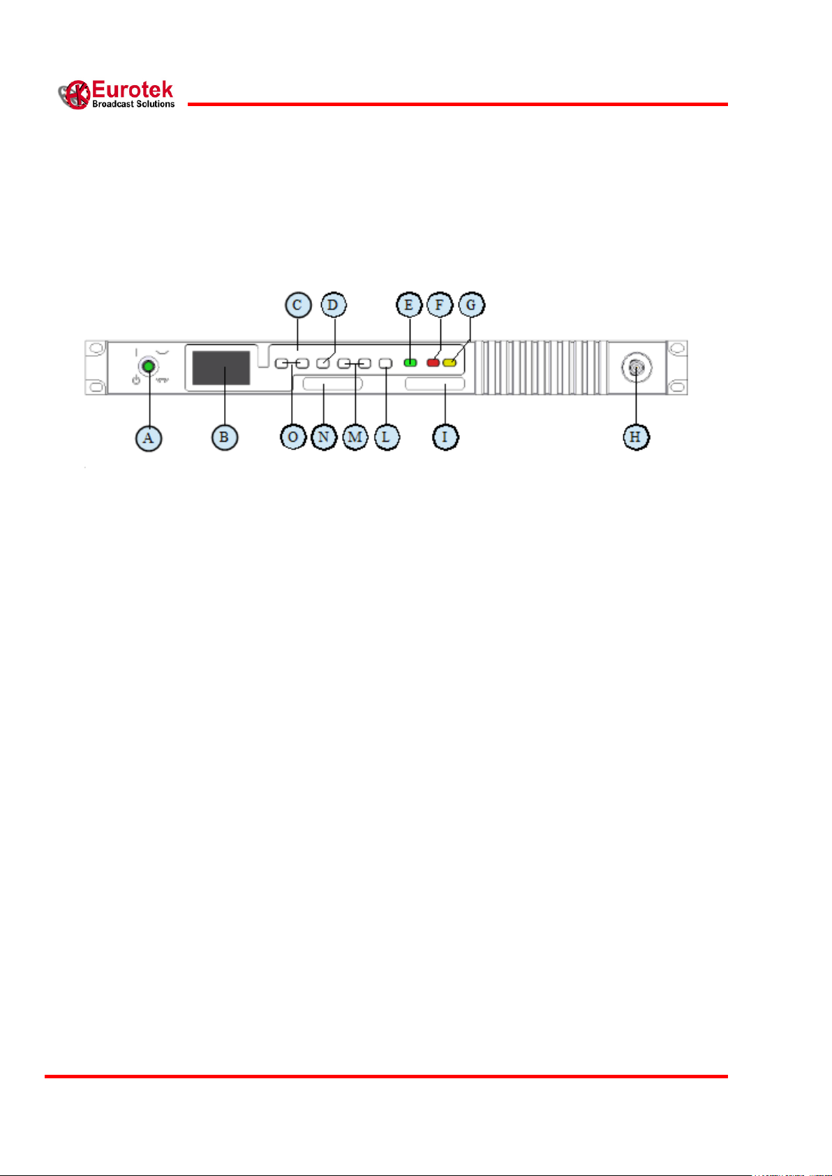
2. FRONT PANEL
2.1 FRONT PANEL VIEW
2.2 FRONT PANEL DESCRIPTION
A) General switch.
B) Amoled Display. (chapter 4, Display and Keyboard)
C) Keyboard. (chapter 4, Display and Keyboard)
D) Enter key.
E) Green LED (ON), for power on indication. (chapter 6, LEDs and ALARMS)
F) Red LED (ACTUAL), for alarm indication. (chapter 6, LEDs and ALARMS)
G) Yellow LED (STORED), for alarms stored indication. (chapter 6, LEDs and ALARMS)
H) I/O connector (BNC).
I) Code and serial number label.
L) Escape key.
M) Modifying variable keys.
N) Eurotek label.
O) Explorer menu and display mode keys.
11
601-000147 Rev. Y
Arch. 5105
25/02/2016
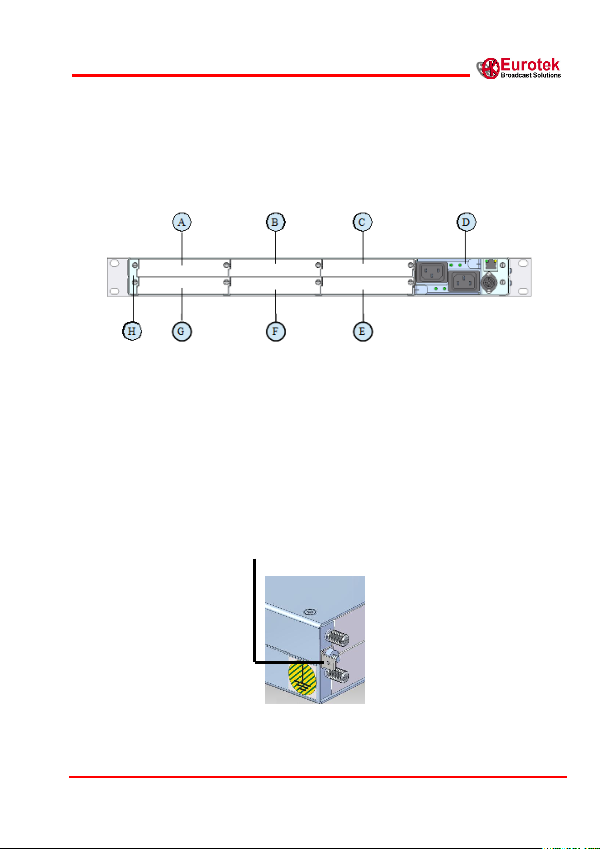
3. REAR PANEL
3.1 REAR PANEL VIEW
3.2 REAR PANEL DESCRIPTION
A) Slot 0.
B) Slot 1.
C) Slot 2.
D) EK-PWS/X* panel.
E) Slot 5.
F) Slot 4
G) Slot 3
H) Additional ground connection
* The different power supplies solutions are described in the EK-PWS/x, EK-PWS/A and EKPWS/D manual.
12
EK-MFR/2
25/02/2016
Arch.5105
601-000147/MN Rev. Y
4. DISPLAY AND KEYBOARD
4.1 DISPLAY AND KEYBOARD DESCRIPTION
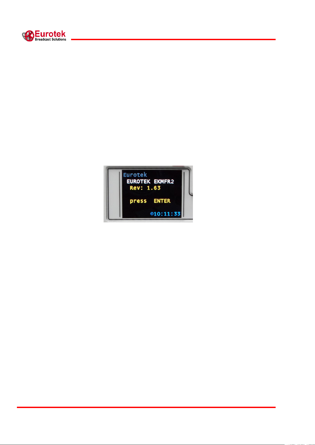
When the general switch (par. 2.2, front panel description) is turned on, the booting of the system is
running. At the end of the booting the EK-MFR/2 display shows, the following configuration:
Pressing the “enter” key (par. 2.2, front panel description), it is possible to start the insertion
password operations (if the user, after the booting, press the “enter” key, the password insertion
procedure immediately started).
A flashing cursor indicates that a special password, of five number, must be inserted. The procedure
for the insertion of the password is explained below:
Press the “modifying variable” keys (par. 2.2, front panel description) to visualize the
number from 0 to 9.
Choose the first value to insert, and confirm it with the “enter” key.
Insert the second value, confirm it, and repeat the procedure until the last number.
If an error occurs, the user must press the “escape” key (par. 2.2, front panel description), the cursor
returns to the previous position and the new value can be inserted. The password value must be
included from 00000 to 99999.
There are two types of password that the user can digit: reading only or reading/writing.
When a password is inserted, in the left down corner on the display it is possible to see the key
symbol with the RO letter if the password is read only type, or RW letter is the password is
read/write type.
13
601-000147 Rev. Y
Arch. 5105
25/02/2016
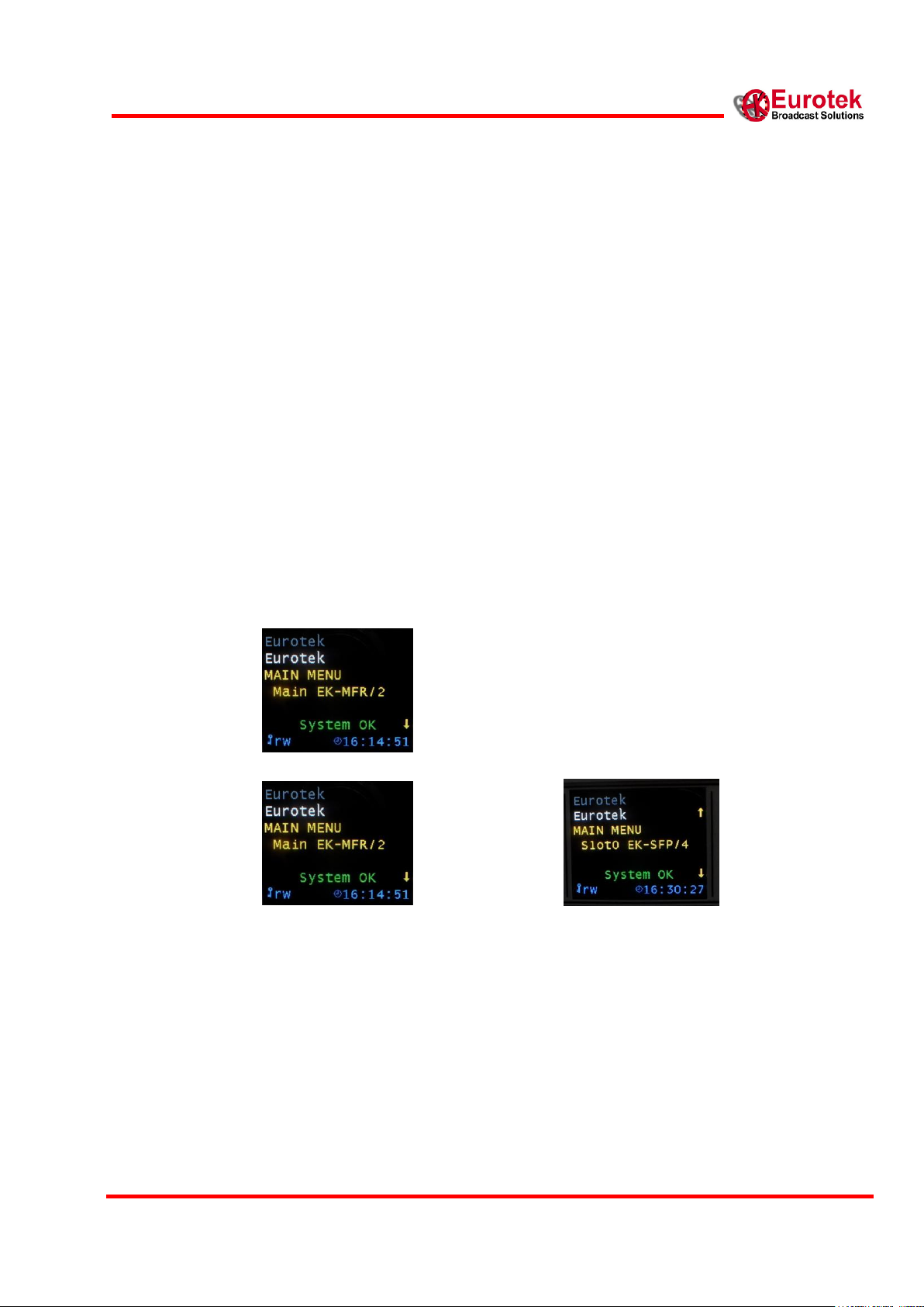
When a type of password is inserted, the user can explore the following main menu:
MAIN MENU
>Main EK-MFR/2
>Slot 0
>Slot 1
>Slot 2
>Slot 3
>Slot 4
>Slot 5
Using the “explorer menu” keys (par. 2.2, front panel description), it is possible to see, on the
display, the boards that the EK-MFR/2 contains and the relative slot associated to the board. The
example below shows the EK-UNM/1 board that is inserted in the slot number 4. Pushing the “enter”
key, it is possible to enter in the selected board menu.
The RW letters appear, in the figure above, near the key symbol; this indicates that the actual active
password allows to read and modify the value of the variables in every board inserted in EK-MFR/2.
If any of the boards is not inserted in a particular slot of the EK-MFR/2, the display shows the
following situation:

14
EK-MFR/2
25/02/2016
Arch.5105
601-000147/MN Rev. Y
Variable name
Variable number
Main EK-MFR/2
>Passwords
>>r/o PWD
>>r/w PWD
>Power Loops
>>Loop 1
>>>Enable 1
>>>Source 1
>>>Target 1
>>>P Goal 1
>>>P Source 1
>>Loop 2
>>>Enable 2
>>>Source 2
>>>Target 2
>>>P Goal 2
>>>P Source 2
>>Loop 3
>>>Enable 3
>>>Source 3
>>>Target 3
>>>P Goal 3
>>>P Source 3
>Get Config
>>Get from
>Save Config
>>Save to
>Miscellaneous
1
2
4
5
6
7
8
9
10
11
12
13
14
15
16
17
18
19
20
21
5. EK-MFR/2 MENU
5.1 MENU REPRESENTATION
The complete EK-MFR/2 menu is described below.

15
601-000147 Rev. Y
Arch. 5105
25/02/2016
>>Pws Upper
>>Pws Lower
>>Volt in 0
>>Volt in 1
>>Volt out 0
>>Volt out 1
>>Board Temp
>>12V rail
>>3.3V rail
>>DC rail in
>>Pws Upper Status
>>Pws Lower Status
>>Time to exit
>>SCI 2
>>Ext Power
>>Fan
>>Reboot
>>Description
>>Sw Rev
>>Panel
>HSB
>>MFR Mode
>>Behavior
>>On Air
>>Reversibility
>Relay
>>Relay 0
>>Relay 1
>>Relay 2
>>Relay 3
>>Relay 4
>Clock Set
>>Year
>>Month
>>Day
>>Hour
>>Minute
>Network
>>IP mode
>>IP address
>>IP netmask
>>GW address
22
23
24
25
26
27
28
29
30
31
32
33
34
35
36
37
41
42
43
44
45
46
47
48
49
50
51
52
53
54
55
56
57
58
59
60
61
62
5.2 MENU DESCRIPTION AND KEYBOARD GUIDE
La descrizione di ogni singolo menu dell' EK-MFR/2 è di seguito riportata:

16
EK-MFR/2
25/02/2016
Arch.5105
601-000147/MN Rev. Y
SOURCE
P GOAL
TARGET
>Passwords
The Passwords menu allows to modify the reading only and the reading/writing password. To do
this, the user must digit the password provided by the Eurotek, when the general switch (par. 2.2,
front panel description) is turned on and the booting of the system is complete (par 4.1 display and
keyboard description).
The next example shows how to change the reading/writing password.
When inside the EK-MFR/2 menu, the “enter” key (par. 2.2, front panel description) is pushed, the
display will show the passwords menu configuration.
Pushing again the “enter” key, the user can enter the two internal menus for the setting of the
passwords value, (in this example the menu is RW/PWD), while pushing the “escape” key (par. 2.2,
front panel description) the display returns to the passwords menu configuration
When the R/W PWD menu is on, the user must digit the “enter” key to start the insertion password
operations (par 4.1 display and keyboard description).
>Power loops
The Power Loops menu allows to control automatically and keep constant the output power of a
transmitter (internal or external to the EK-MFR/2).
It is possible to drive three power loops at the same time, therefore we can adjust three different
transmitters connected to the same EK-MFR/2.
Each loop menu is composed by five parameters: Enable n, Source n, Target n, P Goal n, P Source n.
>> Loop n
>>>Enable n = Enabled/Disabled Power Loop n.
>>>Source n = Selects the slot where reading the transmitter output power.
>>>Target n = Selects the slot where the power loop adjusts the IF gain, in order to obtain the
desired output power.
>>>P Goal n = Sets the desired output power as back-off level [dB].
>>>P Source n = Indicates the back-off level read from the slot selected in Source n [dB].
BLOCK SCHEME OF THE POWER LOOP SYSTEM

17
601-000147 Rev. Y
Arch. 5105
25/02/2016
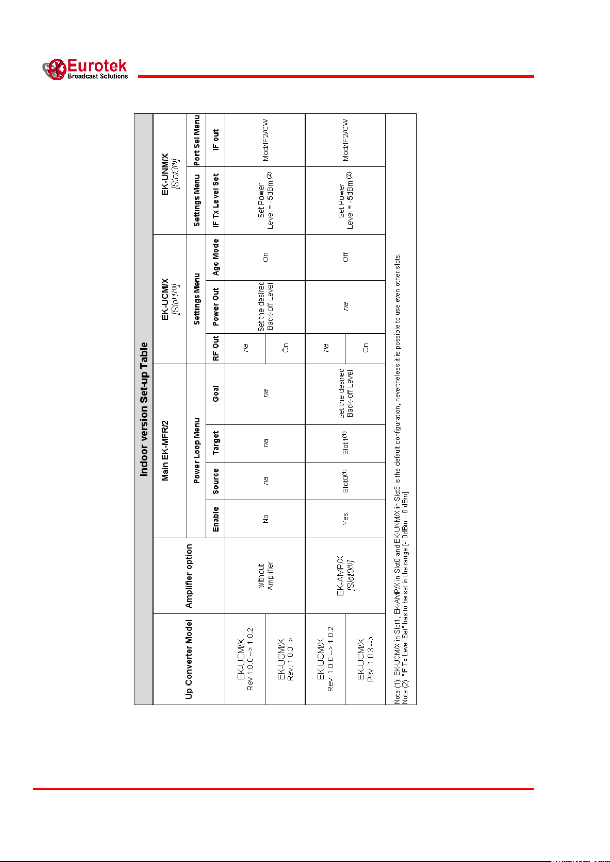
In order to simplify the explanation of how to set all the parameters for a proper operation, it is
useful to separate Indoor version and Outdoor version set-up instructions.
Indoor version
An Indoor version is basically composed by:
EK-MFR/2
EK-UCM/x (where '/x' = band of the Up Converter, e.g. UCM/10 = Up Converter in 10 GHz
Band, see 'EK-UCM/X' User's Handbook).
EK-AMP/x (where „/x‟=band of the Amplifier, see 'EK-AMP/x' User's Handbook), is an
option.
EK-UNM/x (where „/x‟=version of the Modem, see 'EK-UNM/x' User's Handbook).
There are several software revisions of UCM/x which require different set-up, and these are shown in
the table below.
The power loop has to be activated only if an amplifier is used.
The EK-UNM/x output can be set to the desired modality (Mod/IF2/CW) and “IF Tx Level Set” has
to be set in the range [-10dBm ÷ 0 dBm].
(*) The model of the modem can be EK-UNM/2 or EK-UNM/3
18
EK-MFR/2
25/02/2016
Arch.5105
601-000147/MN Rev. Y
Tabella 5.1: : Indoor version Set-up Table

19
601-000147 Rev. Y
Arch. 5105
25/02/2016
The next example explains how to set the Power Loops for a typical Indoor version (IDU).
We suppose to have loaded the EK-MFR/2 with the boards represented in the following figure
Slot 0: EK-AMP/1
Slot 1: EK-UCM/10 (Rev.1.0.3)
Slot 2: Empty
Slot 3: EK-UNM/2
Slot 4: Empty
Slot 5: Empty
We analyze the setting of every single menu of the Power Loops supposing of working with the
QPSK modulations to obtain a back-off of 4 dB relating the saturate power (0 db) of the Amplifier
(EK-AMP/1) inserted in EK-MFR/2. In this case, with reference to the table 5.1, the following values
have to be set:
EK-MFR/2
>>Loop
>>>Enable 1 = yes
>>>Source 1 = slot0
>>>Target 1 = slot1
>>>P Goal 1 = -4db
EK-UCM/10
>> Settings
>>>RF Out = On
>>> AGC Mode = Off
EK-UNM/2
>>Settings
>>>IF Tx Level Set = -5dBm
>>Port Sel
>>>IF out = Mod
Now the EK-MFR/2 keeps the output power of the Amplifier (EK-AMP/1) constant in according to
the power of the up-converter (EK-UCM/10).

20
EK-MFR/2
25/02/2016
Arch.5105
601-000147/MN Rev. Y
PWS/11
PWS/12
PWS/13
PWS/A
PWS/C
PWS/D
PWS/11
PWS/12
PWS/13
PWS0 12V
PWS1 12V
PWS0 3V
PWS1 3V
PWS/A
PWS/C
PWS/D
PWS0 12V
PWS0 3V
Outdoor version
An Outdoor version is basically composed by:
EK-MFR/2
EK-CDP/x (where '/x' = version of the Coax Adapter, see 'EK-CDP/x' User's Handbook).
EK-TRM/1 (oldest ODUs type) or EK-UCT/x (where: '/x' = Band of ODU, e.g. UCT/10 =
Outdoor Up Converter in 10 GHz Band, see 'A4D-ESxT/1 Outdoor Multichannel Transmitter'
User's Handbook)
EK-UNM/X (where „/x‟=version of the Modem, see 'EK-UNM/x' User's Handbook).
Also for EK-CDP/x there are several software revision, for each particular case a proper set-up has to
be used and these are shown in the table below.
Some old models of EK-UCT/x do not send the 'ODU Model' data to the EK-CDP/x board and some
functionality are not available (classified in the table as EK-UCT/na).
Power supply version
In according with the power supply model loaded in the EK-MFR/2 Source and EK-MFR/2 target it
is possible to obatin the following variable combination for the Power Loop Source variable:
 Loading...