

EuroTech Communication VOIP²ALL SERIES, VOIP2 ALL SERIES User Manual

VOIP²ALL SERIES
8 - 16 - 24 Channel Gateway User Guide
Version 5.36z

Contents
VoIP²ALL 8 - 16 - 24 Channel Gateway User Guide
www.eurotech-communication.com
2
CONTENTS
1. INTRODUCTION TO THE VOIP²ALL GATEWAY ....................................................................... 4
1.1. The VoIP²ALL Gateway Solution Overview ................................................................ 4
1.2. About this Manual ..................................................................................................... 5
1.3. Terminology ............................................................................................................... 5
2. INSTALLATION AND SETUP .................................................................................................. 7
2.1. Installation Overview................................................................................................. 7
2.2. Check the Package Items ........................................................................................... 7
2.3. Hardware Installation ................................................................................................ 7
2.3.1. Hardware Overview ................................................................................................... 8
2.3.2. SIM Installation .......................................................................................................... 8
2.3.3. Connecting Cables ................................................................................................... 10
2.4. Software Installation ............................................................................................... 10
3. BASIC SYSTEM SETUP ........................................................................................................ 12
3.1.1. Connecting to the Gateway ..................................................................................... 12
3.1.2. Setting the Clock ...................................................................................................... 13
3.1.3. Changing the Gateway's IP Address ........................................................................ 14
3.1.4. Basic Configuration .................................................................................................. 14
3.1.5. Configuring a Second Master .................................................................................. 16
3.1.6. Basic System Test .................................................................................................... 16
3.1.7. What's Next? ........................................................................................................... 17
4. ADVANCED CONFIGURATION ............................................................................................ 19
4.1. Advanced SIM Configurations ................................................................................. 19
4.1.1. Registering the Local SIM in the Cellular Network Automatically........................... 21
4.1.2. Assigning a Local SIM to Work by Time Table ......................................................... 21
4.1.3. Assigning a Local SIM to Work for a Limited Calling Time ...................................... 22
4.2. Configuring the Internal SIP Server ......................................................................... 24
4.3. Users List ................................................................................................................. 25
4.4. Call Handling ............................................................................................................ 26
4.4.1. Handling Outgoing Calls (Prefixes) .......................................................................... 27
4.4.2. Handling Incoming Calls .......................................................................................... 28
4.5. Cellular Outgoing Call Configurations ..................................................................... 29
4.5.1. IP Restrictions .......................................................................................................... 29
4.6. Cellular Incoming Call Configurations ..................................................................... 30
4.6.1. Calling to an IP PBX .................................................................................................. 30
4.6.2. Calling to a SIP Phone .............................................................................................. 31
4.7. Configuring the SIM Server ..................................................................................... 31
4.7.1. Connecting the GUI Management ........................................................................... 32
4.7.2. Defining the General Settings ................................................................................. 33
4.7.3. Defining SIM Settings .............................................................................................. 34
4.7.4. Assigning a SIM to Work in the Gateway ................................................................ 37

Contents
VoIP²ALL 8 - 16 - 24 Channel Gateway User Guide
www.eurotech-communication.com
3
4.7.5. Blocking SIMs ........................................................................................................... 42
4.7.6. Checking SIM balance .............................................................................................. 43
4.7.7. Monitoring the Balance of SIM ............................................................................... 45
4.7.8. Recharging SIM balance .......................................................................................... 45
4.7.9. Configuring Test Call Profile .................................................................................... 48
4.7.10. Configuring Test SMS .............................................................................................. 49
4.8. Modifying System Settings ...................................................................................... 50
4.8.1. IP Settings ................................................................................................................ 50
4.8.2. Dial Settings ............................................................................................................. 51
4.8.3. Tone Settings ........................................................................................................... 51
4.8.4. Tone Levels .............................................................................................................. 53
4.8.5. Changing the Password ........................................................................................... 53
4.8.6. Resetting the Gateway ............................................................................................ 54
4.9. Configuring Special Features ................................................................................... 54
4.9.1. Network Announcement Message Detection ......................................................... 54
4.9.2. Port Test Calls .......................................................................................................... 55
4.9.3. Source Routing ........................................................................................................ 55
4.9.4. IVR ........................................................................................................................... 56
4.9.5. Callback.................................................................................................................... 58
4.9.6. DISA (Direct Inward Access System) ........................................................................ 58
4.9.7. BCCH Configuration ................................................................................................. 59
4.9.8. Sending and Receiving SMS ..................................................................................... 61
5. MONITORING CALLS .......................................................................................................... 63
5.1. Port Monitor ............................................................................................................ 63
5.2. Call Monitor ............................................................................................................. 64
5.3. CDR (Call Detail Reporting) ...................................................................................... 65
6. APPENDICES ...................................................................................................................... 68
6.1. Appendix A: Working with COM Port ...................................................................... 68
6.2. Appendix B: Sending USSD (Unstructured Supplementary Service Data) commands
in the DEBUG screen ......................................................................................................................... 70
6.3. Appendix C: PC to Gateway Direct LAN Access ....................................................... 72

Introduction to the VoIP²ALL Gateway
VoIP²ALL 8 - 16 - 24 Channel Gateway User Guide
www.eurotech-communication.com
4
1. INTRODUCTION TO THE VOIP²ALL GATEWAY
The Eurotech Communication team is glad you have chosen to use the VoIP²ALL Gateway. We are
confident that due to the quality of our product, simplicity of use and excellent customer support,
the VoIP²ALL Gateway will meet your communication needs.
The goal of our experienced team of engineers, who develop and produce our products, is to meet
the growing demands of our customers in today's communications world.
We hope you enjoy using the VoIP²ALL Gateway and appreciate any comments you may have as we
always strive to improve our products and personal service for all of our customers.
1.1. THE VOIP²ALL GATEWAY SOLUTION OVERVIEW
The 8 - 16 - 24 Channel (1U) VoIP²ALL Gateway, or VoIP²ALL for short, can connect VoIP calls to
cellular networks (CDMA ❘GSM ❘UMTS). The VoIP²ALL contains a SIP Server that can register up to
32 VoIP clients and connect each of these VoIP clients to the cellular network directly, therefore
completely bypassing the local landline telephone company. The VoIP²ALL has up to 24 SIM ports
that can make simultaneous calls to the cellular network. You can also call from a VoIP client to
another VoIP client.
The 8 and 16 Channel VoIP²ALL can be upgraded to include an internal SIM Server that can hold up to
64 additional SIMs (two cards of 32 SIM each). You can configure the Gateway to direct calls through
the most economic SIM. Additionally, the VoIP²ALL is able to load SIMs from 20 external SIM Servers
simultaneously.

Introduction to the VoIP²ALL Gateway
VoIP²ALL 8 - 16 - 24 Channel Gateway User Guide
www.eurotech-communication.com
5
Each cellular port has one Local SIM. Due to the flexibility of our Gateway, you can also call from one
of the cellular ports to another cellular port. Each cellular port can be programmed to work with any
of the SIMs in the SIM Servers at any given time.
1.2. ABOUT THIS MANUAL
This manual is for use with the VoIP²ALL 8 - 16 - 24 channel Gateway.
Our VoIP stand-alone unit product range is:
2ch- For SOHO and SMB’S
4ch- corporate
8ch- enterprise
16ch-24-32ch -Enterprise and heavy duty traffic
All of the above units are compatible for use in our SIM Server System.
1.3. TERMINOLOGY
The following is a list of important terms used in this guide and their definitions:
Gateway - A VoIP²ALL unit with cellular ports.
SIM - SIM card or chip

Introduction to the VoIP²ALL Gateway
VoIP²ALL 8 - 16 - 24 Channel Gateway User Guide
www.eurotech-communication.com
6
SIM Server - A VoIP²ALL series unit with a SIM Server program containing SIM cards and no
cellular cards.
Internal SIM Server - A SIM Server program that runs on a Gateway, allowing access to SIM cards
in the Gateway.
External SIM Server - A SIM Server program that runs on an external SIM Server, or another
Gateway, allowing access to SIM cards in the external SIM Server.
Master card - A card that controls the operation of the VoIP²ALL, containing a DSP processor with
a Linux based operating system.
Port (ch)- A port is single channel that can send call(s).
Cellular Card (Slave card) - A card with cellular ports (modules).
SIM Server Card - A SIM Server card that has 32 SIM sockets, which is located in a SIM Server or
Gateway.
VoIP - A protocol for transmitting voice calls on Ethernet networks.
SIP - A protocol for registering VoIP clients and making VoIP calls.
SIP Server - A virtual PBX that can register and connect SIP phones.
SIP Account - A user name and password which is given to register a SIP phone.
SIP Registration - The process of the initial connection of the SIP account to the SIP Server.
Authorization - SIP registration with username and password
SIP Client - A SIP phone that is registered in a SIP Server.
Internal SIP Server - The SIP Server that is built into the Gateway.
SIM Registration - The activation of the SIM in a cellular network. The SIM must be registered to
make calls.
Local SIM - A SIM on a cellular card.
Virtual SIM - A SIM from a SIM Server.

Installation and Setup
VoIP²ALL 8 - 16 - 24 Channel Gateway User Guide
www.eurotech-communication.com
7
2. INSTALLATION AND SETUP
This section will guide you through the installation and setup process, including basic configuration
and a system test to ensure that all components are working properly. These steps are MANDATORY
to run the VoIP²ALL, unless otherwise indicated.
After completing this section your Gateway is functional for basic operations. You may choose to
make further configurations. For details, see Advanced Configuration on page 19.
2.1. INSTALLATION OVERVIEW
Perform the following steps to install and setup your system:
1) Check the items delivered in your package - see Check the Package Items on page 7.
2) Install SIMs - see Hardware Installation on page 7.
3) Connect LAN cables, antennas and power supply - see Connecting Cables on page 10.
4) Install the PC management application using the CD provided - see Software Installation on page
10.
5) Power up the Gateway.
6) Perform basic setup - see Basic System Setup on page 12.
7) Make basic system configurations - see Basic Configuration on page 14.
8) Test the Gateway - Basic System Test on page 16.
9) (Optional) Make advanced system configurations - see Advanced Configuration on page 19.
2.2. CHECK THE PACKAGE ITEMS
Make sure that your package contains the following components before installation:
Main Hardware Device - The VoIP²ALL Gateway.
Quick Installation Guide - Brief installation explanations.
Software Installation CD - Gateway Manager CD for MS-Windows Management Application.
Includes the User Manual file and additional auxiliary utilities.
Cellular Antennas
LAN Connection Cable
RS-232 Serial PC Comport (COM) connection cable (RJ-45 to RS-232 COM). This facilitates
debugging and direct access to the configuration files. This is referred to as the ‘Com Cable’ in
this manual.
Input: 110/240 V AC 50-60 Hz, Output: power supply cable
2.3. HARDWARE INSTALLATION
This section describes how to install the VoIP²ALL Gateway Hardware.
Installation and Setup
VoIP²ALL 8 - 16 - 24 Channel Gateway User Guide
www.eurotech-communication.com
8
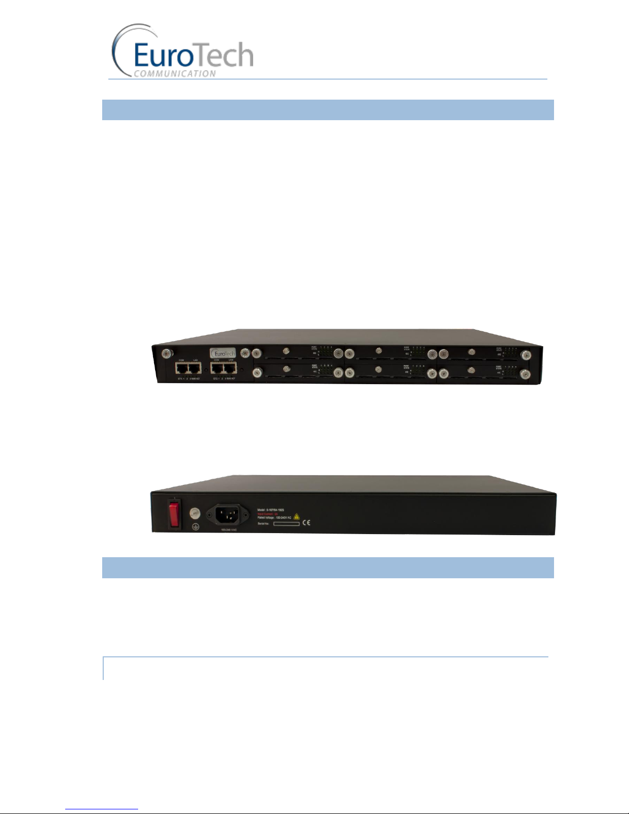
2.3.1. HARDWARE OVERVIEW
The Gateway (1U) consists of four main parts:
Chassis - Housing a power supply 12v DC and a motherboard. The motherboard contains a data
bus that connects all of the cards.
Master Card - Located on the left side of the Gateway it contains the LAN and COM
connection(s).
Cellular Cards - Located to the right of the master card. Each card contains 4 cellular ports. Each
port has one Local SIM. Each card has one antenna connection for all 4 ports.
SIM Server Card - In units with an internal SIM Server (optional), there are two additional cards
on the right side of the cellular cards. Each card contains 32 SIM sockets. All the SIM Server cards
are hot swappable.
Front Panel
Back Panel
2.3.2. SIM INSTALLATION
The following sections describe how to install and remove SIMs in the VoIP²ALL Gateway.
Installing Local SIMs on page 8
Removing Local SIMs on page 9
Installing SIMs in the Internal SIM Server (Optional) on page 9
2.3.2.1. INSTALLING LOCAL SIMS
On the bottom of each cellular card there are 4 labeled ports to install SIM cards.

Installation and Setup
VoIP²ALL 8 - 16 - 24 Channel Gateway User Guide
www.eurotech-communication.com
9
To install a SIM in a cellular card:
10) Locate the ICC - Port on the cellular card.
11) Position the SIM in the port SIM socket so that the SIM's metal contact is facing up and the
snubbed edge is on the right hand side directed into the SIM socket.
12) Gently push the SIM card into the SIM socket until you hear a click. The SIM is now installed.
2.3.2.2. REMOVING LOCAL SIMS
To remove a Local SIM
1) Locate the port containing the SIM you want to remove.
2) Press gently on the SIM until you hear a click.
3) Pull the SIM from the socket completely.
Important: Do not leave the SIM half way in or out. This will disable the port from loading SIMs from
the SIM Server.
2.3.2.3. INSTALLING SIMS IN THE INTERNAL SIM SERVER (OPTIONAL)
Each SIM Server card has 32 SIM chambers which are marked from 1 to 32.
To install a SIM in the internal SIM Server:
1) Extract the SIM Server card by holding the handle and pulling the card from the Gateway.
2) To open the chamber:
From the top side - gently push the metal slide in the direction of the connector and lift.
From the bottom side - pull the metal slide from the direction of the connector and lift.
3) Position the SIM card in the chamber with the metal contacts facing downwards and the snubbed
edge facing to the:

Installation and Setup
VoIP²ALL 8 - 16 - 24 Channel Gateway User Guide
www.eurotech-communication.com
10
right - for top side
left - for bottom side
4) Push the metal housing down towards the card.
Note: If you have inserted the SIM in the proper manner, the chamber will close flat to the Server
card and cannot slide out.
5) Slide the metal housing back into the locked position. The SIM card is now in place.
6) Repeat for each SIM card.
Note: After removing the SIM Server card, you must wait one minute before re-inserting it to the
Gateway for the SIM to be scanned.
2.3.3. CONNECTING CABLES
On the master card there are two sets of LAN and COM connectors marked ST1 and ST2.
Connect the following to the Gateway:
LAN cable - The LAN cable is used to connect the system to the internet network.
For 8 and 16 channel - Connect the LAN cable to the RJ-45 marked LAN of ST1.
For 24 channel - Connect both LAN cables to the RJ-45s marked LAN of ST1 and ST2.
Antennas - Connect antenna cable for each cellular card.
Position the antennas at least 40 centimeters apart and more than 1.5 meters from the Gateway.
Power Supply Cable - Connect the power supply cable from your 110-240V 50-60Hz power outlet
to the VoIP²ALL Gateway power connector/adapter.
COM Cable - The COM connection is not essential for day to day use.
For 8 and 16 channel - Connect the COM cable to the RJ-45 marked COM of ST1.
For 24 channel - Connect both COM cables to the RJ-45s marked COM of ST1 and ST2.
2.4. SOFTWARE INSTALLATION
Configuration is performed on an auxiliary computer by installing the VoIP²ALL Management
software CD for MS-Windows Application.

Installation and Setup
VoIP²ALL 8 - 16 - 24 Channel Gateway User Guide
www.eurotech-communication.com
11
To install the VoIP²ALL Management Software on a MS-Windows PC
1) Insert the VoIP²ALL Management Installation CD into the CD drive of the PC.
2) Navigate to the installation CD drive.
3) Double-click setup.exe.
4) Click Next. The Destination Folder appears.
5) Select the destination folder by clicking Change and navigating to the destination.
6) Click Next.
7) Click Install. The VoIP²ALL Management application begins installation. You will be prompted
when the installation is complete.
8) Click Finish and remove the CD.
Note: If the VoIP²ALL icon appears on the Desktop, the application was successfully installed.
Basic System Setup
VoIP²ALL 8 - 16 - 24 Channel Gateway User Guide
www.eurotech-communication.com
12
3. BASIC SYSTEM SETUP
This section describes how to perform basic configurations and operations in the Gateway.
The Management application gives you access to all of the tasks you need to use VoIP²ALL system.
To open the application, click the VoIP²ALL icon on the Desktop or open from the directory where
the application is located (default: Start>Programs>Eurotech-Communication>VoIP²ALL
Management).
The first tasks you need to perform are:
Connecting to the Gateway on page 12
Setting the Clock on page 13
Changing the Gateway's IP Address on page 14
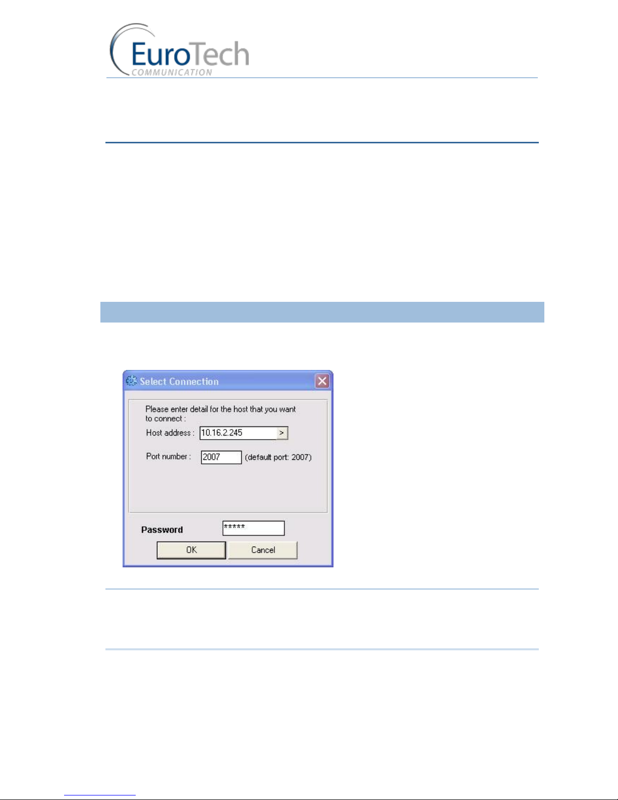
3.1.1. CONNECTING TO THE GATEWAY
To connect to the Gateway:
1) On the Main Toolbar, click Connect.
The Selected Connection window appears.
2) In Host address, enter the IP Address of the VoIP²ALL Gateway (The default 10.16.2.245).
Note: If you can't remember the IP Address of the Gateway, see Appendix A: Working with COM Port
on page .
If the PC does not have an IP address in the same Subnet as the Gateway, see Appendix C: PC to
Gateway Direct LAN Access on page .
3) In Port number, enter the Port Number of the Gateway (The default port is 2007).
4) In Password, enter the password of the Gateway (The default password is admin).
5) Click OK to connect.
Basic System Setup
VoIP²ALL 8 - 16 - 24 Channel Gateway User Guide
www.eurotech-communication.com
13
Note: You must wait 30 seconds after connecting the power to the VoIP²ALL Gateway for the
initialization process to end before connecting with the PC Management.
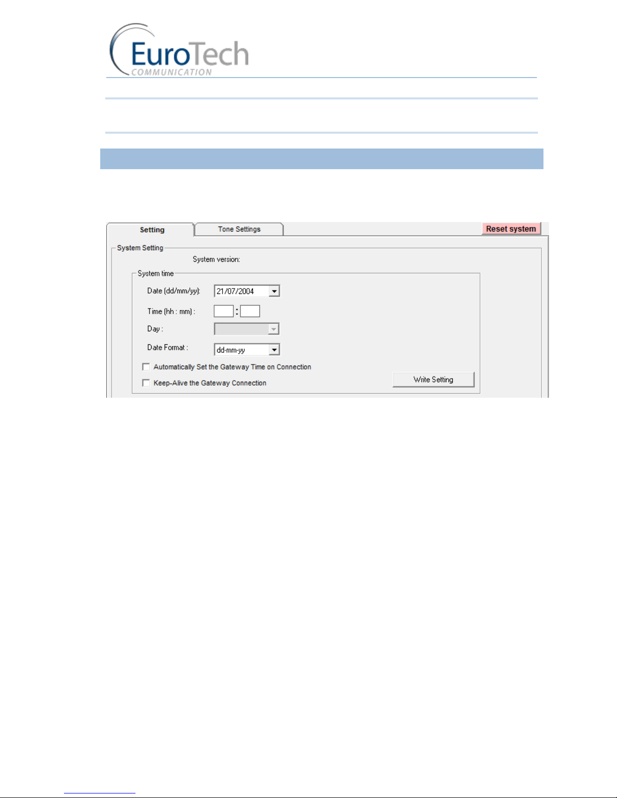
3.1.2. SETTING THE CLOCK
To set the clock:
1) On the Main Toolbar, click System and select the Setting tab.
The following window appears:
2) In Date, define the required date.
3) In Time, define the local time.
4) In Date Format, select the format in which the date is displayed, (e.g. Day/Month/Year or
Year/Month/Day).
5) (Optional) Click Automatically Set the Gateway Time on Connection to synchronize time with
the PC on connection.
6) (Optional) Click Keep-Alive the Gateway Connection - this reconnects the PC software if an
interruption occurred.
7) Click Write Settings to save the changes to the date and time.
Basic System Setup
VoIP²ALL 8 - 16 - 24 Channel Gateway User Guide
www.eurotech-communication.com
14
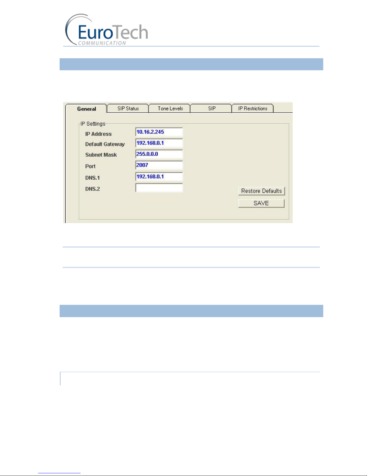
3.1.3. CHANGING THE GATEWAY'S IP ADDRESS
To change the IP Address of the Gateway
1) On the Main Toolbar, click VoIP and select the General tab.
The following window appears:
2) In IP Settings, enter the new IP Address, Default Gateway and Subnet Mask.
3) Click Save.
Note: Wait 30 seconds for the configuration to be saved so that the changes will be applied when the
Gateway is restarted.
4) On the Main Toolbar, click System and select the Setting tab.
5) Click Reset system to restart the Gateway.
6) After 30 seconds you can reconnect with the new IP address.
3.1.4. BASIC CONFIGURATION
This section includes the following basic configurations:
SIM Configuration on page 14
SIP Configuration on page 15
Prefix Configuration (Call Handling) on page 15
LAN Configuration on page 16
3.1.4.1. SIM CONFIGURATION
Before making a call from a Gateway port, the port SIM must be registered in the network.
There are two basic modes for the Gateway to work:
Active by Default - The Local SIM will register in the cellular network automatically when
inserted.

Basic System Setup
VoIP²ALL 8 - 16 - 24 Channel Gateway User Guide
www.eurotech-communication.com
15
Work by Time Table - The Local SIM will register in the cellular network only when preset in the
Time Table. For details, see Assigning a Local SIM to Work by Time Table on page 21.
To set the Local SIM to register by default:
1) On Main Toolbar, click Ports. On the left you will see list of all the ports.
2) Select the General tab.
3) In Default SIM, select Local SIM work by default.
4) Click Save.
5) On the Main Toolbar, click Monitor to view the status of the cellular ports.
The following is a single port monitor. The number of monitors displayed depends on the number
of ports in the Gateway.
When the SIM is registered correctly, the port monitor appears in green.
3.1.4.2. SIP CONFIGURATION
The Gateway has an internal SIP Server that is able to register up to 32 SIP clients. A SIP client can be
a:
VoIP phone
External SIP Server
IP PBX/Soft switch
By default, the internal SIP Server works without authentication. You can register without a password
and choose any user name. The user name must be a number.
To configure YOUR SIP to send calls to the Gateway without registration
1) Open YOUR SIP Configuration in the external SIP Server or IP PBX.
2) Configure your SIP to send calls to the Gateway, according to the following parameters:
The SIP Server IP Address - the IP address of the Gateway
The SIP User ID (optional) - the defined user name for this SIP client
The Authentication Password (optional) - the defined password for this SIP client
3) Save the configuration settings.
3.1.4.3. PREFIX CONFIGURATION (CALL HANDLING)
Each port can have a list of defined prefixes. When a number is dialed, the Gateway checks the prefix
table and routes the call to a port according to the dialed prefix. The first matched prefix on the list is
selected.
If more than one port has a matching prefix, the Gateway creates a prefix group of these ports and
divides calls with this prefix amongst the group.

Basic System Setup
VoIP²ALL 8 - 16 - 24 Channel Gateway User Guide
www.eurotech-communication.com
16
To configure a prefix to a port:
1) From the Main Toolbar, click Ports.
2) Select a port from the list on the left.
3) Select the Prefixes tab. A prefix table for the selected port is displayed.
4) Enter the prefixes you want to add to this port in the table.
There are two rules:
The default prefix is *. If the prefix of a port is *, then all the calls that do not match a prefix in
another port are routed through this port.
If two or more ports have the same prefix then the Gateway will divide the calls between the
ports.
Note: To avoid losing calls, make sure that the cellular prefix is different than the VoIP and Host
prefixes.
1) (Optional) You can modify the dialing number received from the SIP which the Gateway uses to
dial out by using the following parameters:
Remove Prefix - Select how many digits to remove from the beginning of the dialed number.
Add Prefix - Enter the digits to be added at the beginning of the number.
2) Click Save.
3.1.4.4. LAN CONFIGURATION
When the Gateway is working behind NAT or a Firewall, you must make sure that the ports of the
Gateway are accessible from the public IP to the Gateway local IP.
The following ports need to be forwarded to the Gateway:
Port 2007 - to make connection with the PC software
Port 2008 and port 2009 (optional) - to allow access to the internal SIM Server
Port range from 5060 to 6066 - for the SIP registration and calls
3.1.5. CONFIGURING A SECOND MASTER
When working with a 24ch VoIP²ALL Gateway the second part of the master (ST2) must be
configured. Follow the same configuration steps which you performed for the 1st part of the master
above.
3.1.6. BASIC SYSTEM TEST
Once you have completed the basic configuration described in the previous sections, you can now
test that the system is functioning normally using the following procedures.
To call from your SIP client (i.e. IP PBX) through the Gateway to the cellular network:
1) On the Main Toolbar, click Monitor.

Basic System Setup
VoIP²ALL 8 - 16 - 24 Channel Gateway User Guide
www.eurotech-communication.com
17
2) Send a call from your SIP to the Gateway.
3) Check the monitor to see that the number was dialed correctly and the call was connected.
Troubleshooting
In case the call was not connected, check the following:
Confirm that the number was compatible with the network by dialing this number directly from
your mobile phone.
If you see that the number is not accepted, reconfigure the port prefix table to allow this
number. See Prefix Configuration (Call Handling) on page 15.
If the call is not displayed on the monitor:
Change the prefix of this port to * and retry.
If the call is accepted but not connected - reconfigure the port prefix and retry.
If the call is still not displayed - check that this prefix is not assigned to another port (i.e. VoIP,
H323, Host). If so, reconfigure that port's prefix so it does not conflict and retry.
If the call is still not displayed - check that the SIP ports are forwarded to the Gateway,
specifically port 5060 to 6066.
If the call is connected but there is no audio:
Check that the ports are forwarded to the Gateway, specifically port 5060 to 6066.
Check the audio directly with a SIP phone by bypassing the IP PBX.
Testing a port with a VoIP phone
Perform the following test to ensure that your audio is functional by bypassing the public IP.
To register a VoIP phone in the Gateway :
1) Open the VoIP phone configuration.
2) Configure the VoIP phone according to the following parameters:
The SIP Server IP Address - the IP address of the Gateway
The User ID (optional) - the defined user name for this SIP client
The Authentication Password (optional) - the defined password for this SIP client
3) Save the configuration settings.
To call from your VoIP phone through the Gateway to cellular network:
1) In the port you wish to use, configure the prefix to *. See Prefix Configuration (Call Handling) on
page 15.
2) Dial the number of the mobile phone.
The call is routed to the mobile phone through the port.
3) Check that the audio in the local network is functional.
If so, then the Gateway is functional and the audio problem is caused because ports 5060 to 6066
are not accessible from the public IP. Check your IP settings.
3.1.7. WHAT'S NEXT?
After you have completed the installation and basic system setup, you can choose to perform the
following:

Basic System Setup
VoIP²ALL 8 - 16 - 24 Channel Gateway User Guide
www.eurotech-communication.com
18
Advanced Configuration on page 19
Configuring the SIM Server on page 31
Modifying System Settings on page 50
Configuring Special Features on page 54
Monitoring Calls on page 63

Advanced Configuration
VoIP²ALL 8 - 16 - 24 Channel Gateway User Guide
www.eurotech-communication.com
19
4. ADVANCED CONFIGURATION
The following sections describe how to perform advanced configuration in the VoIP²ALL Gateway:
Advanced SIM Configurations on page 19
Cellular Outgoing Call Configurations on page 29
Cellular Incoming Call Configurations on page 30
Configuring the SIM Server on page 31
Modifying System Settings on page 50
Configuring Special Features on page 54
4.1. ADVANCED SIM CONFIGURATIONS
For each cellular port there is a Local SIM. Each port's SIM can work only with that cellular port.
There are two basic modes of working with the Local SIM:
Active by Default - The Local SIM will register in the cellular network automatically when
inserted.
Work by Time Table - The Local SIM will register in the cellular network only when preset in the
Time Table. For details, see Assigning a Local SIM to Work by Time Table on page 21.
Each Local SIM can be configured with its own parameters which take effect when the Local SIM is
registered on the cellular network.
To configure the Local SIM:
1) On the Main Toolbar, click Ports.
2) Select a port from the port list.
Advanced Configuration
VoIP²ALL 8 - 16 - 24 Channel Gateway User Guide
www.eurotech-communication.com
20
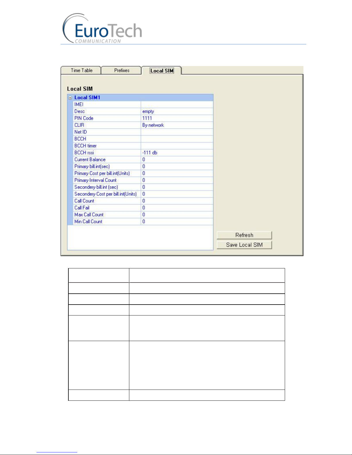
3) Select the Local SIM tab. The following window appears:
4) Define the parameters as needed. See the following table for parameters and their descriptions:
PARAMETER
DESCRIPTION
PIN Code
The PIN Code for the SIM when it is PIN Code protected.
CLIR
Show or Hide the number of the SIM
Net ID
Lock the SIM on a specific network.
BCCH
Lock the SIM on a specific BCCH.
When this parameter is empty, the SIM locks on the best
reception BCCH.
BCCH Timer
This function rotates the BCCH.
The rotation is performed according to the BCCH Timer,
measured in seconds, between all BCCH which have better
reception than the BCCH rssi.
When using the BCCH Timer, the BCCH parameter must be
empty.
BCCH rssi
The minimum reception for rotation.

Advanced Configuration
VoIP²ALL 8 - 16 - 24 Channel Gateway User Guide
www.eurotech-communication.com
21
CALL DURATION PARAMETERS
PARAMETER
DESCRIPTION
Current Balance
The total number of units for the SIM.
A value greater than 0 must be defined.
Primary Bill Interval
The interval of time (in seconds) for the beginning of the call.
Primary Interval Count
The number of times the Primary Bill Interval will repeat.
Primary Cost per Bill Int
The number of units the Primary Bill Interval will count.
Secondary Bill Interval
The intervals of time (in seconds) after the end Primary Bill
Interval.
Secondary Cost per Bill
Int
The number of units the Secondary Bill Interval will count.
Max Call
The maximum number of calls per connection.
Min Call
The minimum number of calls per connection.
STATISTICS (READ ONLY)
Call Count
The number of calls the SIM made the last time it was
connected.
Call failed
The number of failed calls the SIM made the last time it was
connected.
5) Click Save.
4.1.1. REGISTERING THE LOCAL SIM IN THE CELLULAR NETWORK AUTOMATICALLY
When the Local SIM is active by default it registers in the cellular network automatically when
inserted in the SIM socket.
To set the SIM to be active by default:
1) From the Main Toolbar, click Ports.
2) In the port list on the left side of the window, select General.
3) In Default SIM, select Local SIM work by default.
4) Insert the SIMs to the cellular port’s Local SIM sockets.
5) On the Main Toolbar, click Monitor. The monitor window appears displaying the status of the
cellular ports.
4.1.2. ASSIGNING A LOCAL SIM TO WORK BY TIME TABLE
When the Local SIM is active by Time Table it registers in the cellular network according to the
schedule defined here.
When you set the time table, you mark a Local SIM to work at a specific time.

Advanced Configuration
VoIP²ALL 8 - 16 - 24 Channel Gateway User Guide
www.eurotech-communication.com
22
To define a Time Table:
1) From the Main Toolbar, click Ports.
2) In the ports list on the left side of the window, select General.
3) In Default SIM, select Local SIM work by time table.
4) On the left side of the window, select a port from the ports list.
5) From the Available SIMs list, select L1 (Local 1).
6) In Type, select the type of schedule you want to define from the following options:
Monthly - The table will show all the days of the month.
Weekly - The table will show all the days of the week.
7) In Swapping Type, select one of the following options:
Time Table - The SIM is replaced at the end of its defined time in the Time Table. In this mode
you set up a Time Table and define which SIM will work in which hour.
Call Duration - The SIMs are replaced when they end their defined calling minutes. In this
mode you define a list of SIMs in the table. For each SIM in the list you define the amount of
calling units to be used. Each SIM will work for the defined calling minutes and then be
replaced with the next SIM on the list.
Manual - This gives you the option of manually connecting a SIM immediately. This is
recommended for temporary use only, generally by support in the debug process.
8) In the Time Table, define the hour and day for the Local SIM to register.
In the time slot you can see the information of the SIM in this format: L1
9) Click Save.
10) Insert the SIMs to the cellular ports Local SIM sockets.
11) At the defined time, the Local SIM will register in the cellular network.
4.1.3. ASSIGNING A LOCAL SIM TO WORK FOR A LIMITED CALLING TIME
In the Call Duration mode, each SIM works for a defined number of call minutes.
At the beginning of the day, the Gateway registers a SIM from the list and then counts down the
number of units defined for that SIM until it reaches 0.
The Gateway then registers the next SIM from the list. This process continues until all of the SIMs on
the list have finished their defined time units.
The Gateway resets the time unit count to the original definitions at the beginning of every month or
week, depending on the Type selected in the Time Table.
The calculation of the units per interval
The Gateway calculates the call duration by intervals. An interval is a minimum billing duration.
When making a call shorter than 1 interval, you will be charged the entire interval cost.

Advanced Configuration
VoIP²ALL 8 - 16 - 24 Channel Gateway User Guide
www.eurotech-communication.com
23
You must define the cost and time duration of the intervals.
Calculations are as follows (See the parameters in the figure above.):
At the beginning of the call the Gateway counts the units according to the Primary bill interval.
The number of units for each interval are defined in Primary Cost per billing interval.
This Primary bill interval is repeated according to the number of times defined in Primary
Interval Count.
The rest of the call uses the Secondary Bill Interval.
For example:
For a call of 1 minute and 59 seconds, the unit calculations are:
From the beginning of the call, two 30 second intervals (Primary bill. int) according to the
Primary Interval Count for a total of 1 minute.
Each interval is 2 units according to the Primary Cost per bill int. definition.
Therefore, the charge calculation is: 2 intervals of 2 units per interval = 4 units
The remainder of the call takes 3 intervals of the Secondary Bill Interval for 59 secs.
Therefore, the charge calculation is: 3 intervals of 1 unit per interval = 3 units.
The total amount of units for this call will be 4 + 3 = 7 units.
Current Balance
The Current Balance is the number of units the SIM has left to use.
At the end of each call the unit count is updated. Once the Current Balance of a SIM has reached 0,
you will not be able to work again with that SIM until you set a new balance.
There are two common methods of counting units:
seconds
minutes
If you are workiing by seconds and you want to limit the Current Balance to a specific number of
minutes, the Current Balance (units) must be the number minutes X 60.
To configure the SIM Call Duration parameters:
1) On the Main Toolbar, click Ports.
2) Select a port from the port list.
3) Select the Local SIM tab.
4) Define the following parameters:
Primary Bill Interval
Primary Interval Count
Primary Cost per Bill Int

Advanced Configuration
VoIP²ALL 8 - 16 - 24 Channel Gateway User Guide
www.eurotech-communication.com
24
Secondary Bill Interval
Secondary Cost per Bill Int
Current Balance
5) Click Save.
To define the Call Duration SIM list:
1) On the Main Toolbar, click Ports.
2) From the ports list on the left, select a port.
3) Select the Time Table tab.
4) In Type, select a Time Table type.
5) In Swapping Type, select Call duration.
6) In Available SIMs, select the Local SIM (L1).
7) In the Time Table, click a cell. A dialog box appears.
8) In the dialog box, enter the amount of units you want to limit the SIM to that day.
9) To unselect the cell, click it again.
10) Click Save.
4.2. CONFIGURING THE INTERNAL SIP SERVER
The Gateway has an internal SIP Server that is able to register up to 32 SIP clients. A SIP client can be
a:
VoIP phone
External SIP Server
IP PBX/Softswitch
The internal SIP Server can work with or without authentication. When working with authentication,
the SIP account must be entered into the Users list.
To configure the SIP Server:
1) On the Main Toolbar, click VoIP.
2) Select the SIP tab.
3) In the Internal SIP Settings section of the window, define the following parameters:
SIP Port - The TCP port of the SIP Server. The default is 5060.
RTP Start Port - The first port in the RTP port range. The default is 5066.
RFC2833 Payload Type - The type of payload to be used by the SIP. The default is 101.
Codec 1 - Codec 4 -
The priority of the Codec which the SIP Server uses when making outgoing VoIP calls.
Note: The CODEC priority is relevant only in calls to SIP, the codec for the incoming calls from SIP is
determined by the SIP that sends the calls to the Gateway.
Authentication - When enabled a user name and password is required to register the
VoIP²ALL in the internal SIP Server.
Realm - The name of the SIP Server realm of operation.
 Loading...