

EUROSEC CP 8, CP 7 Installation Instructions Manual

CCCCPPPP7777 //// CCCCPPPP88
88
IIIINNNNSSSSTTTTAAAALLLLLLLLAAAATTTTIIIIOOOONN
NN
IIIINNNNSSSSTTTTRRRRUUUUCCCCTTTTIIIIOOOONNNNSS
SS
TM
TM


Contents
Introduction . . . . . . . . . . . . . . . . . . . . . . 2
Mains Safety . . . . . . . . . . . . . . . . . . 2
Good Working Practice . . . . . . . . . . 2
Installation . . . . . . . . . . . . . . . . . . . . . . . 3
Control Panel Location . . . . . . . . . . 3
Mounting the Control Panel . . . . . . . 3
Mounting the RKP . . . . . . . . . . . . . . 3
Wiring . . . . . . . . . . . . . . . . . . . . . . . . . . 4
General Detector Wiring . . . . . . . . . 4
Wiring Global Tampers . . . . . . . . . . 4
Wiring Contacts . . . . . . . . . . . . . . . 4 - 5
Wiring Passive Infra-Red Detectors . 5
General Bell Box Wiring . . . . . . . . . 6
Bell Tamper Ring . . . . . . . . . . . . . . . 6
Sample Bell Box Connections . . . . . 6 - 7
Wiring Notes . . . . . . . . . . . . . . . . . . 8
Control Panel Connections . . . . . . . 8
Programming . . . . . . . . . . . . . . . . . . . . . 9
Terminology . . . . . . . . . . . . . . . . . . 9
Engineer Programming Mode . . . . .10
Programmable Engineer Options . . .11 - 13
Engineer / User Mode . . . . . . . . . . .14
Engineer Reset . . . . . . . . . . . . . . . .15
Anti-Code Reset . . . . . . . . . . . . . . .15
Resetting to Factory Defaults . . . . . .16
Troubleshooting . . . . . . . . . . . . . . . . . .17 - 18
Specifications . . . . . . . . . . . . . . . . . . . .19
System Details . . . . . . . . . . . . . . . . . . .20
IIIInnnnssssttttaaaallllllllaaaattttiiiioooonnnn MMMMaaaannnnuuuuaaaall
ll
eeeeuuuurrrroooosssseeeecc
cc
II
II
nn
nn
tt
tt
rr
rr
oo
oo
dd
dd
uu
uu
cc
cc
tt
tt
ii
ii
oo
oo
nn
nn
Introduction
The eurosec control panel is supplied as a blank fronted end station complete with RKP. Up to
3 additional may be fitted if required. The unit is fully programmable by the installation and
comes pre-programmed with a set of factory defaults that will suit most installations. Seven
programmable zones are available on the CP7 and eight zones on the CP8
IMPOR
IMPOR
TTANT!
ANT!
Input: AC230V +/-10% ~50Hz 200mA Max. 49W Max
For Indoor Use Only
Nominal Temp Range: 0° - 50° Centigrade
This equipment is intended only for use as a Security Alarm Control Panel. Adequate ventilation
away from heat and humidity must be provided. The unit must be fixed securely to a nonflammable surface using suitable fixings.
All mains wiring must be to BS7671 (1992) IEEE wiring regulations (or appropriate international
regulatory standards). See relevant section within this manual for connection to mains supply.
Provision is provided for an earth connection within the mains connection block, this is for the
protection of the wiring and is not a functional part of the unit.
All low voltage (alarm) wiring must be to the appropriate international regulatory standards and
comply to good wiring practice.
Replacement fuses should be of the same type and rating conforming to IEC127.
The maximum current draw from the unit for all output combinations must not exceed 1Amp.
The unit is intended for use with a suitable re-chargeable battery permanently connected to the
appropriate terminals.
Mains Safety
The main unit must be connected to a mains supply via a 3Amp unswitched fused spur. This
must be carried out by a suitably qualified electrician. If you are in any doubt please contact your
local electricity company for advice.
Good Working Practice
The reliability of any security system may be greatly enhanced by following a few good working
practices. Do not connect the mains supply to any rings that have fridges, freezers or
fluorescent lights connected to them. When running low voltage alarm cables avoid running
parallel to mains wiring, if you do so separate by a least nine inches. When crossing mains
cables do so at 90°
PPPPaaaaggggeeee 22
22

eeeeuuuurrrroooosssseeeecc
cc
IIIInnnnssssttttaaaallllllllaaaattttiiiioooonnnn MMMMaaaannnnuuuuaaaall
ll
Control Panel & RKP Location
Consideration needs to be given to the location of the Control Panel & RKP with regards to-
The surface that the unit(s) are to be fixed to should be firm, vibration free, damp free and fire
resistant.
Access for the routing of mains and low voltage wiring.
Service Access to the unit(s).
Operation of the keypad.
Operation of ACE (if fitted).
Readability of the RKP display(s).
Mounting the Control Panel
Unscrew the two cover retaining screws and remove the front cover.
The PCB is held in place by two lower PCB retaining lugs and two upper sprung latches.
Push both upper latches upwards and pull the PCB forward and upward in one movement.
With the PCB removed from its retainers offer the unit to the wall and mark for the three fixing
points. Under no circumstances should you drill through the base.
Remove any knockouts that are required from the base and also the cover screw caps from
the moulding pips in the base and retain them for use after fixing the front cover in place.
Using suitable rawl plugs and 3 No.8 x 1.5” (min) screws fasten the base to the wall but do
not tighten until all cabling is in place.
Mounting the RKP
Lower the front cover of the RKP and unscrew the single cover fixing screw.
Offer the RKP base to the wall and mark the three fixing positions. Under no circumstances
should you drill through the base.
Remove one of the cover screw caps and retain for use after fixing the front cover.
Using suitable rawl plugs and 3 No.6 x 1” (min) screws fasten the base to the wall offering
the connecting cable through a suitable aperture in the base as you do so.
Wire the RKP as shown in the wiring section of this manual.
Replace the cover and tighten the cover fixing screw.
When finished put the cover screw cap in on the cover screw and push into place.
PPPPaaaaggggeeee 33
33
II
II
nn
nn
ss
ss
tt
tt
aa
aa
ll
ll
ll
ll
aa
aa
tt
tt
ii
ii
oo
oo
nn
nn
IIIInnnnssssttttaaaallllllllaaaattttiiiioooonnnn MMMMaaaannnnuuuuaaaall
ll
eeeeuuuurrrroooosssseeeecc
cc
General Detector Wiring
We would strongly suggest that you adopt a colour scheme for the detector wiring of your
system. This will enable you to quickly determine the source of any problems that may occur.
The security industry does not have recommended colour schemes because of the nature of
the wiring, one suggested scheme is given below.
Red/Black.................... Alarm Pair
Green.......................... + Supply
White........................... - Supply
Yellow/Blue.................. Tamper Pair
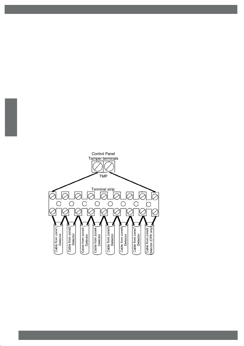
Wiring Global Tampers
One pair of tamper terminals is provided on the control panel PCB for tamper protection of the
zones. This is termed as a Global Tamper, one simple method of wiring Global Tampers is
shown in Fig. 1 below.
Fig. 1 Wiring Global Tampers
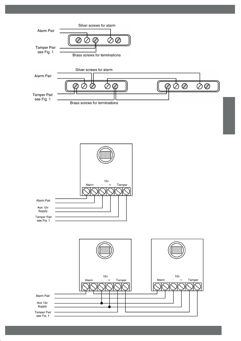
Wiring Contacts
Many types of contacts are available and fall in to two categories, surface or flush.The method
of operation is the same for both. One half of the contact is fitted to the door or window frame,
inside is a reed switch that is pulled together in the presence of a magnetic field. The other half
that is fitted to the opening section of the door or window contains the magnet. These devices
are referred to as normally closed (NC or N/C). The gap allowed for reliable operation will vary
(usually between 5mm & 20mm) dependant on the model used, you should check this
specification with your supplier before fitting.
In Figs. 2 & 3 we have used 5 screw surface contacts for clarity of the illustration.
PPPPaaaaggggeeee 44
44
WW
WW
ii
ii
rr
rr
ii
ii
nn
nn
gg
gg
eeeeuuuurrrroooosssseeeecc
cc
IIIInnnnssssttttaaaallllllllaaaattttiiiioooonnnn MMMMaaaannnnuuuuaaaall
ll
Fig. 2 Wiring Single Contact
Fig. 3 Wiring Double Contact (on the same zone)
Wiring Passive Infra-Red Detectors
It is essential when using Passive Infra-Red Detectors that you refer to the manufacturers
instruction as to the positioning and settings of the detector. This section is intended as a
guide to the wiring of the detectors.
Fig. 4 Wiring Single PIR
Fig. 5 Wiring Double PIR (on same zone)
PPPPaaaaggggeeee 55
55
WW
WW
ii
ii
rr
rr
ii
ii
nn
nn
gg
gg
Notes
Positions of terminals will vary
according to make.
All PIR wiring diagrams apply
also to Dual Technology
Detectors and Vibration sensors.
IIIInnnnssssttttaaaallllllllaaaattttiiiioooonnnn MMMMaaaannnnuuuuaaaall
ll
eeeeuuuurrrroooosssseeeecc
cc
General Bell Box Wiring
As with the detector wiring we would suggest that you adopt a standard for your Bell Box wiring,
the colour scheme below is provided as a suggestion only.
Hold Off Supply +................. Red
Hold Off Supply - .............. .. Black
Trigger................................... Blue
Tamper Return...................... Yellow
Strobe +................................ Green
Strobe -................................. White
Bell Tamper Ring
It should be noted that many bell boxes that are fitted with rechargable batteries will sound when
the battery is connected. This connection may take the form of manually connecting the battery
wires to terminals or placing a link into the On position. Dependant on the bell box being used
the sounder may sound when the battery is connected unless power from the control panel is
connected or the bell box tamper is closed or in some cases both. Most bell boxes produce
high volume noise adequate ear protection MUST be used.
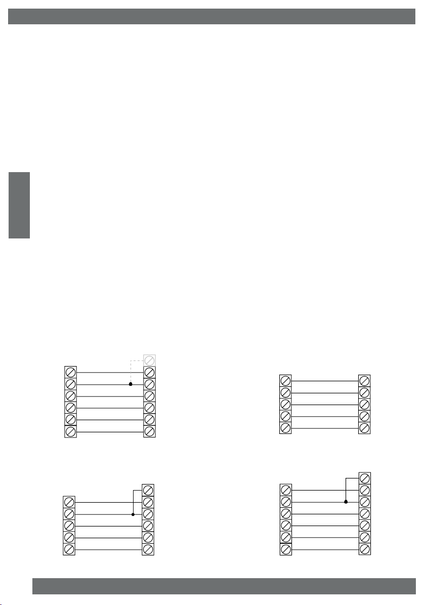
Sample Bell Box Connections
Below is shown general and sample bell box connections for some of the popular bell boxes that
are available.
PPPPaaaaggggeeee 66
66
WW
WW
ii
ii
rr
rr
ii
ii
nn
nn
gg
gg
Bell +
Bell -
Bell Hold -
SAB TMP
Strobe +
Strobe -
Tamper Return
Supply -
Bell Trigger
Supply +
Strobe -
Strobe +
eurosec control
panel terminals
General bellbox
connections
Check bellbox
terminal positions
Tamper Feed
Bell +
Bell -
Bell Hold -
SAB TMP
Strobe -
TMPR
12v
Bell SW-
0V
STR SW-
eurosec control
panel terminals
Novagard Delta
bellbox connections
Check bellbox
terminal positions
Bell +
Bell -
Bell Hold -
SAB TMP
Strobe -
R-TMP
0V
S-
12V+
ST-
eurosec control
panel terminals
Delta E, Novagard 1E & 6
bellbox connections
Check bellbox
terminal positions
TMP-F
Bell +
Bell -
Bell Hold -
SAB TMP
Strobe +
Strobe -
R Tamper Return
-12v Supply
Bell SW-
+12v Supply
Strobe -
Strobe +
eurosec control
panel terminals
Novagard 2&4
bellbox connections
Check bellbox
terminal positions
F Tamper Feed
Fig.6A
Fig.6B
Fig.6C
Fig.6D
 Loading...