

Page 1
InstallationManual
ISSUESIX
Verifier/2464
VERIFIER
QUIT
!
Verifier
Page 2

Page 3

Europlex Technologies [Ireland] Ltd, Clonshaugh Industrial Estate, Clonshaugh, Dublin 17, Ireland.
Tel: 353 - 1 - 8485111 Fax: 353 - 1 - 8485161 e-mail: [email protected]
Europlex Technologies [UK] Ltd, Unit 11, Malmesbury Business Park, Malmesbury SN16 9JU, Wiltshire, England.
Tel: 01666 - 825430 Fax: 01666 - 824423 e-mail: [email protected]
WARNING
While this system is an advanced design security system, it does not offer guaranteed
protection against burglary, fire or other emergency. Any alarm system, whether commercial or domestic, is subject to compromise or failure to warn for a variety of reasons.
Therefore, good installation practices, thorough testing and regular maintenance by the
installing company and frequent testing by the user are essential to ensure continuous
satisfactory operation of the system. It is recommended that the installation company offer
a maintenance program and instruct the user with the correct procedure for use and testing
of the system.
COPYRIGHT
© Europlex Technologies [Ireland] Ltd (hereby referred to as Europlex) 1998. All rights
reserved. No part of this publication may be reproduced, transmitted, stored in a retrieval
system, or translated into any language or computer language in any form or by any means
electronic, mechanical, magnetic, optical, chemical, manual or otherwise without the prior
written permission of Europlex.
DISCLAIMER
Europlex make no representations or warranties with respect to the contents hereof and
specifically disclaim any implied warranties of merchantability or fitness for any particular
purpose. Further Europlex reserve the right to revise this publication and to make changes
from time to time in the contents hereof without the obligation of Europlex to notify any
person of any such revision.
Verifier 24/64 Installation Guide Issue 06 - 1998
Page 4

Page 5

Contents
Introduction .............................................................. i
About this Manual ..................................................... i
General Features ...................................................... ii
1 Chapter One - Basic System Set-
Up
2 Chapter Two - System Expansion
Basic System Configuration ...................................1-1
Control Panel P.C.B. ..............................................1-2
Control Panel Cabinet ...........................................1-3
Control Panel Connecting Power ...........................1-4
Remote Keypad Display .........................................1-5
RKD Base ..............................................................1-6
RKD DIL Switch Addressing ....................................1-7
LCD Display ..........................................................1-7
General Installation Guidelines .............................1-8
Environmental Conditions ......................................1-8
Installation Check List ............................................1-9
Commercial/Domestic SystemTypes........................2-1
Block System System Types ....................................2-2
Split System System Types ..............................2-4
Powering Devices ..................................................2-5
Connecting Zones .................................................2-5
System Expansion Diagram ....................................2-6
Line Encoder Modules ...........................................2-7
Input LEM ..............................................................2-7
Output LEM ...........................................................2-8
A-LEM & C-LEM Coding Zones/Outputs .................2-9
Input/Output Module ..........................................2-10
I/O Module Programming Zones/Outputs ............2-11
I/O Module - Trouble Indication ..........................2-13
I/O Module - Trouble Shooting ............................ 2-14
Chapter Three - Engineer Menu Start Up ................................................................3-1
n I
Page 6

Main Menu ...........................................................3-2
System ..................................................................3-3
Zones ...................................................................3-6
Timers ...................................................................3-7
Outputs ................................................................3-8
Communications ...................................................3-9
Utilities ...............................................................3-10
walktest ...............................................................3-11
zone monitor .......................................................3-12
output control ......................................................3-13
on-line report.......................................................3-14
soak test ..............................................................3-15
Variables ............................................................3-16
Change Code .....................................................3-18
Typing Text & Word Library ..................................3-19
3 Chapter Four - User Menu User Menu ............................................................4-1
4 Chapter Five - Zone Types &
Outputs
Inhibit ...................................................................4-2
View Log ...............................................................4-3
Bell Test ................................................................4-4
Set Time ................................................................4-5
Set up Users ..........................................................4-6
Change Code .......................................................4-9
Force Call ...........................................................4-10
Unset ..................................................................4-11
Accept Alerts........................................................4-11
Home (Partguard A) ............................................4-12
Night (Partguard B) .............................................4-13
Block Set..............................................................4-14
Block Unset..........................................................4-15
Full Set ...............................................................4-16
Zone Types ...........................................................5-1
Zone Attributes ......................................................5-4
Setting Modes Effect on Zone Types........................5-5
Outputs .................................................................5-6
5 Chapter Six - Peripherals Connecting a Printer ..............................................6-1
Remote Communication via DM1200 ....................6-2
Mounting the DM1200 P.C.B..................................6-2
II n
Page 7

Connecting a Eurocom 400/800.............................6-3
Direct Connect to a PC...........................................6-3
FileSaver................................................................6-4
6 Appendix Word Library..........................................................A-1
Sensor Attribute .....................................................A-2
System Default Settings.......................................... A-3
Technical Specification ...........................................A-4
Index
n III
Page 8

Introduction
The VERIFIER 24 is a microprocessor-based security control panel, which is based on well proven
technology, in both hardware and software. It is an 8 zone fully programmable analog multiplexing
control panel, expandable to 24 zones, with each zone fully monitored using dual end of line
resistors. It is the ideal solution for small to medium size commercial premises and prestigious
domestic properties.
Programming of the Verifier 24 is a simple process via the system remote keypad(s). This highly
sophisticated new keypad incorporates many impressive new features, such as its clear 16character supertwist backlit LCD display compensating for poorly lit areas. It offers extremely user
friendly Menu-driven software, reducing operator response time to a minimum. In addition it
incorporates a time saving ‘‘Quick key’’ function, enabling the user to select exactly what is
required without having to scroll through menu sequences.
The Verifier 24 is a sophisticated yet extremely user friendly multiplex control panel offering the
complete security solution.
The number of zones is expandable to 64 with the VERIFIER 64 system. The increased memory
capacity of the 64 also means many additional features, all of which are detailed in the manual.
Introduction
About this Manual
This manual has been produced with a view to providing the installation engineer with any
technical information required for the installation and operation of the Verifier 24 control panel.
The manual also serves for the expanded Verifier 64 panel, which has the same functionality as the
24 with additional features. This document has been divided into the following sections:
l Chapter 1 - Basic System Set-Up. This chapter contains installation details for a basic 8-zone
(hardwired) system. Other topics covered are Safety/Installation guidelines and
Environmentalconsiderations.
l Chapter 2 - System Expansion. This chapter explains how to expand a system up to 24
zones; System Types; Connection/Coding LEMs; Connection/Programming I/O Modules.
l Chapter 3 - Engineer Menu. Powering up the system, Engineer Menu, Text Entry & Word
Library Operation.
l Chapter 4 - User Menu. Setting and Unsetting Modes; Alert Accept; All User Functions.
l Chapter 5 - Zone Types & Outputs. An explanation of Zone Types/Attributes and Output
Types.
l Chapter 6 - Peripherals. Connection diagrams for connecting a Printer, DM1200, PC,
Eurocom and FileSaver.
l Appendix - Word Library; Sensor Attribute; System Defaults; Technical Specification.
i
Page 9

General Features
l On-board zones - There are 8 on-board zone inputs provided, with a common terminal for
each zone pair. These inputs are dual End Of Line monitored loops, and use 1KOhm resistors
across the zone contacts.
l Multiplex Data Line Connection - A further 16 zones (56 on the Verifier 64) may be added to
the system by connecting Line Encoder Modules (LEMs), Input/Output modules or a
combination of both to the Multiplex Data Line.
l Remote Keypads - Up to 16 addressable Remote Keypad Displays may be connected to
the Multiplex Data Line.
l True Split System - The Verifier 24/64 boasts a TRUE two-way SPLIT system. This feature allows
each tenant the luxury of a completely independent system under the control of one
multiplex panel. True split implies that each tenant has their own RKD, access codes etc.
and is completely oblivious to the system functionality of the other split system. Either system
type may be assigned to a split, thus permitting various combinations such as Split 1 =
Commercial, Split 2 = Domestic ; Split 1 = Block, Split 2 = Commercial, etc. (see "System
Expansion").
Introduction
l 16 Users - In addition to the Engineer and Master User (s), the system allows up to 16 general
users to be defined (32 users on the VERIFIER 64 ). Each user is identified by name, and can
have a flexible level of access.
l 250 Event Log - The system’s 250-event log (up to 500 on the VERIFIER 64) records each
event/action, user name, and is timed to the second.
l System guided walk test with report - "Force call" feature for simple remote tech. support.
l Bell & Auxiliary fuse monitoring - Low/missing battery monitoring - Mains fail and restore
indication.
l 2 x on-board fused bell/siren outputs - 4 x on-board open collector outputs for digital
communicator, etc.
The Verifier 24/64 offers 2 types of system operation - STANDARD (Commercial/Domestic) and
BLOCK system.
l Commercial/Domestic System - The standard system can be set for either Commercial or
Domestic mode. In Commercial mode the setting modes appear as PARTGUARD A,
PARTGUARD B and FULL SET. In Domestic mode they appear as HOME, NIGHT and FULL SET.
(see p.2-1 for an explanation).
l Block System - The Verifier can also be subdivided into a Block system. Block C is a common
area and will not arm until both Block 1 and 2 are fully armed. This is typically used in office
complexes but can have domestic applications as well (see "System Expansion"). Verifier 24
allows for 2 separate blocks, Verifier 64 allows for 4.
ii
Page 10
ChapterOne
Page 11
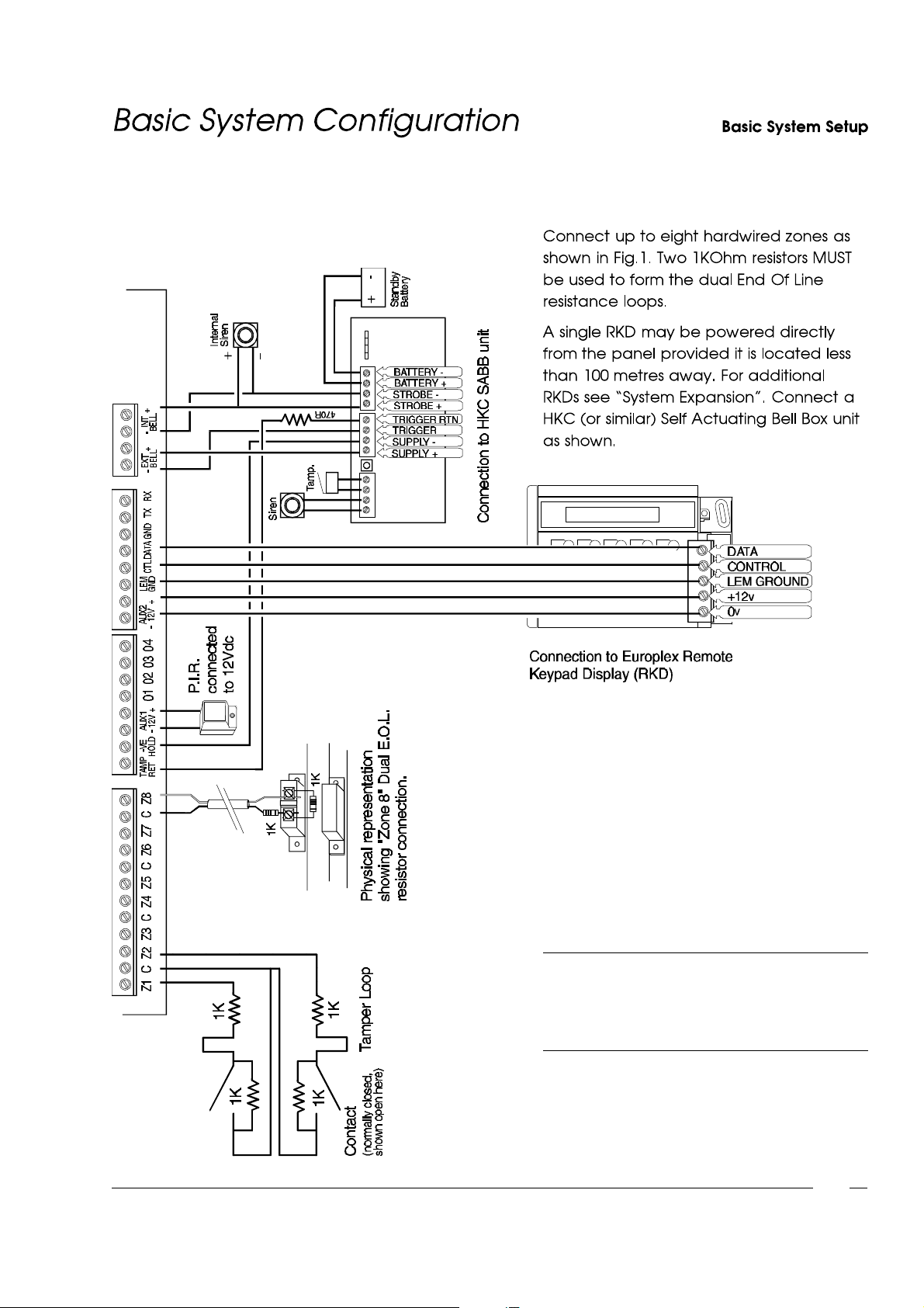
NOTE: After adding zones to the system the
engineer must select"RESET PANEL"
from the "Utilities" menu (p.3-10) so that
the system recognisesthe zones.
Fig. 1 - Basic System Configuration
1-1
Page 12
1-2
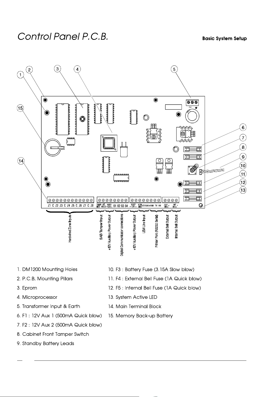
Fig. 2 - Control Panel P.C.B.
Page 13
(
(
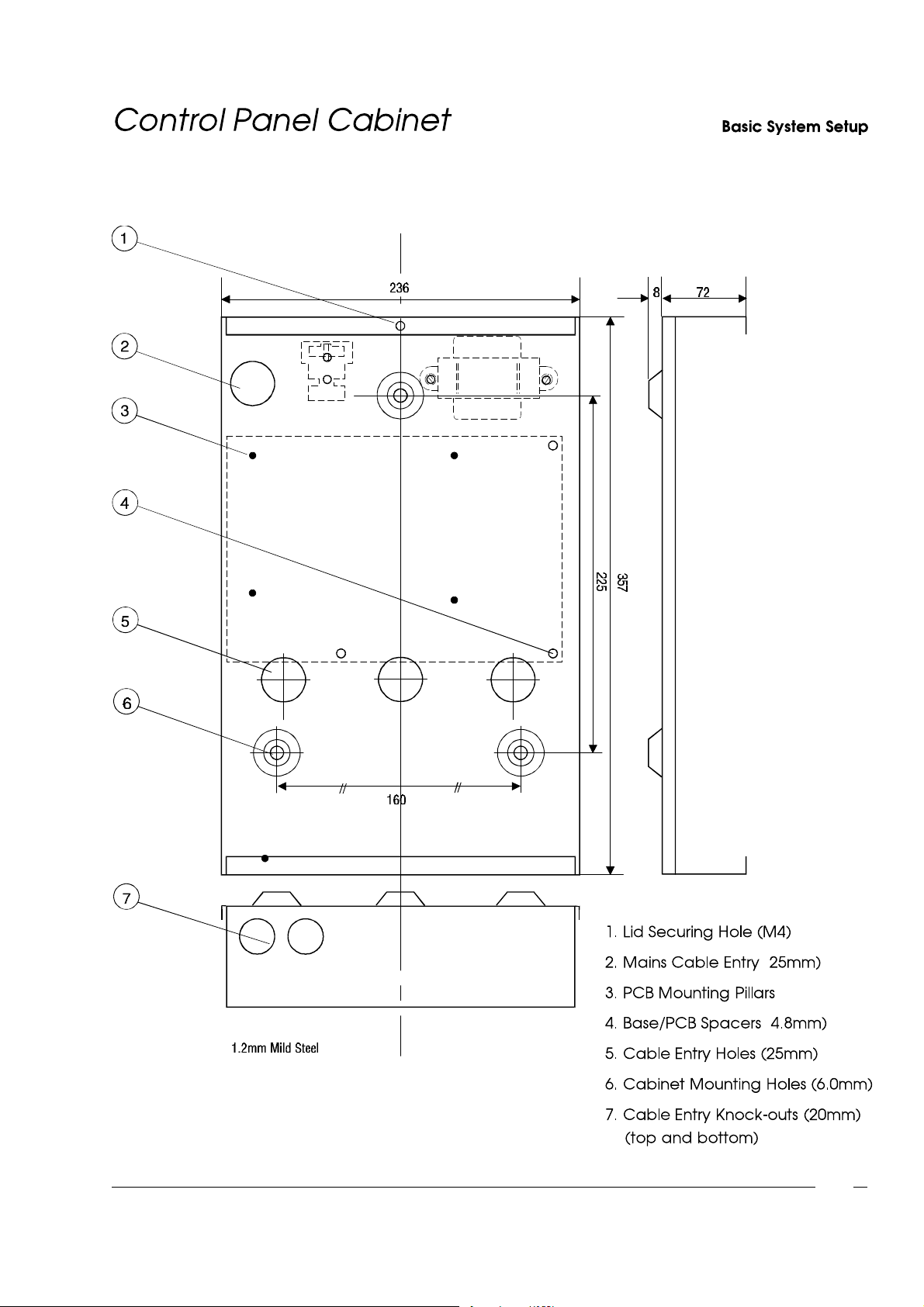
Fig. 3 - Control Panel Cabinet
(Diameter shown)
1-3
Page 14
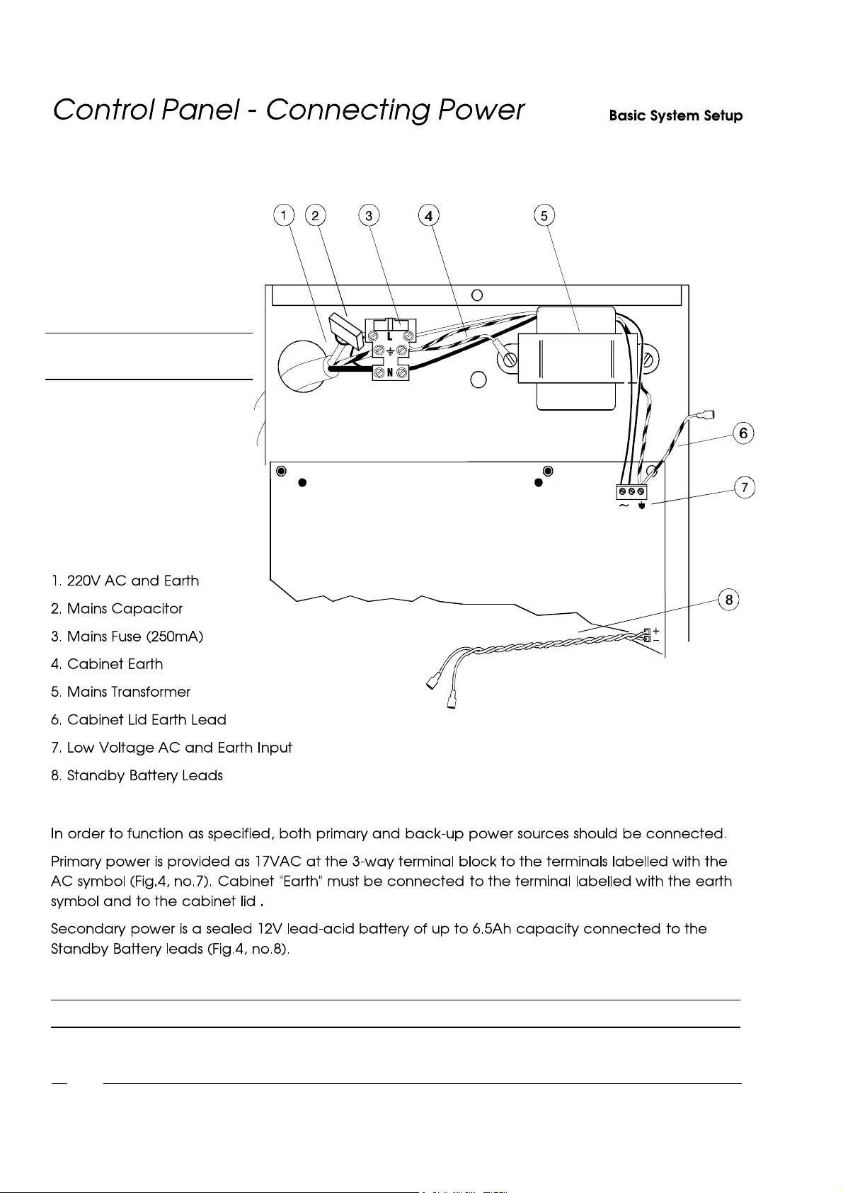
Fig. 4 - ConnectingPower
WARNING: Isolate unit from mains
supply before maintenance.
NOTE: Before initialising power, read Page 1-8 "Installation Guidelines" carefully!
1-4
Page 15
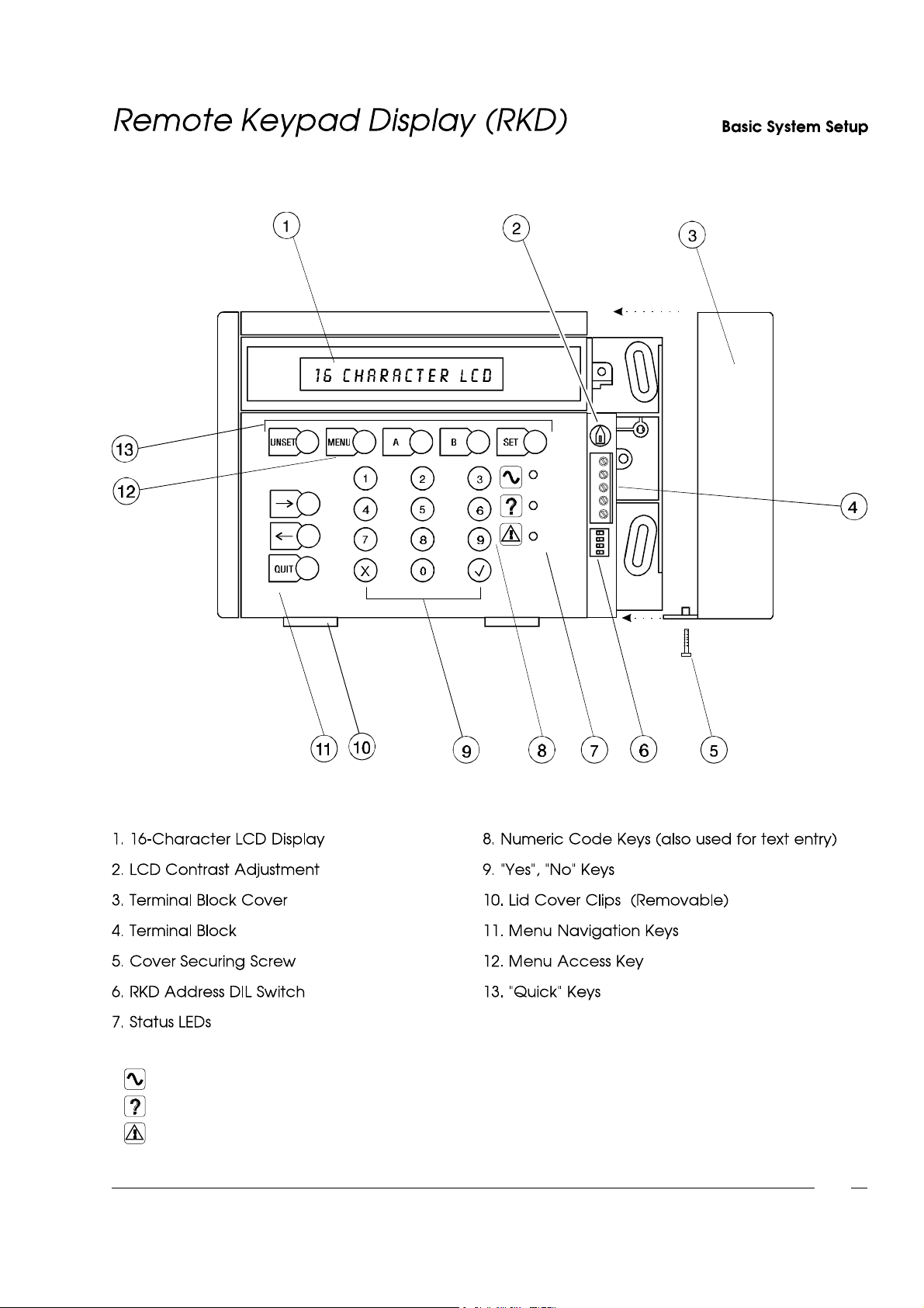
Fig. 5 - Remote KeypadDisplay
Green - Flashing = Mains Fault. Steady = Mains Present.
Yellow - Flashing = System Message. Steady = Message "Alert Accepted" but condition still present.
Red - Flashing = System Partially Set. Steady = System Setting.
1-5
Page 16
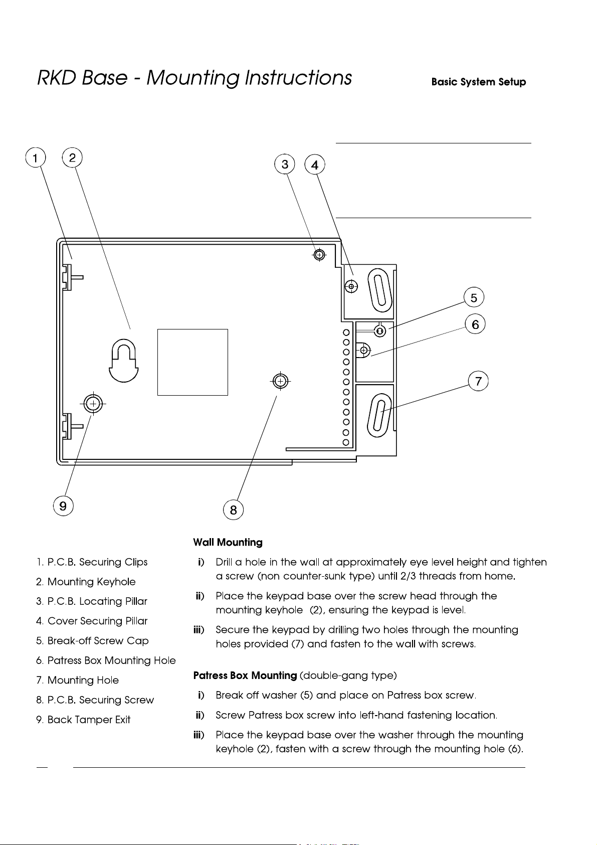
NOTE: Fig.6 shows the RKD base with Front
Cover and P.C.B. removed for
illustrativepurposes only - it is not
necessaryto remove these items when
mounting the RKD.
1-6
Fig. 6 - RKD Base
Page 17
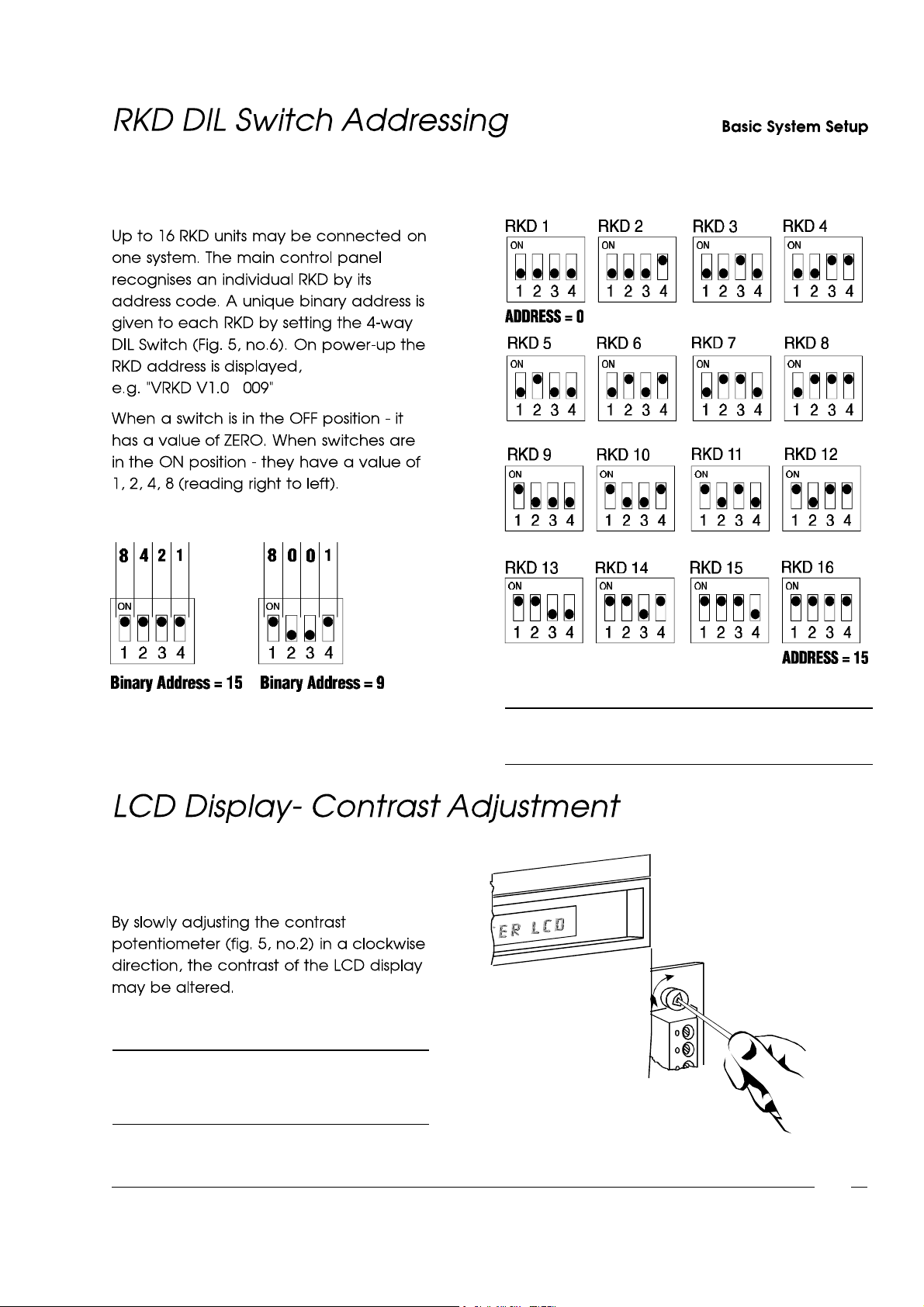
Fig. 8 - RKD DIL Switch Addressing
Fig. 7 - Binary AddressExamples
NOTE: When the potentiometer is adjusted to
the end of its travel the display is no
longer visible.
NOTE: Split systems -RKD 1 to 8 (address 0-7) = Split 1
RKD 9 to 16 (address8-15) = Split 2
Fig. 9 - Contrast Adjustment
1-7
Page 18

1-8
° ° .
Page 19
1-9
Page 20

1-10
Page 21

ChapterTwo
Page 22

"
"
"
"
2-1
Page 23
System ExpansionSystem Expansion
l
l
l
l
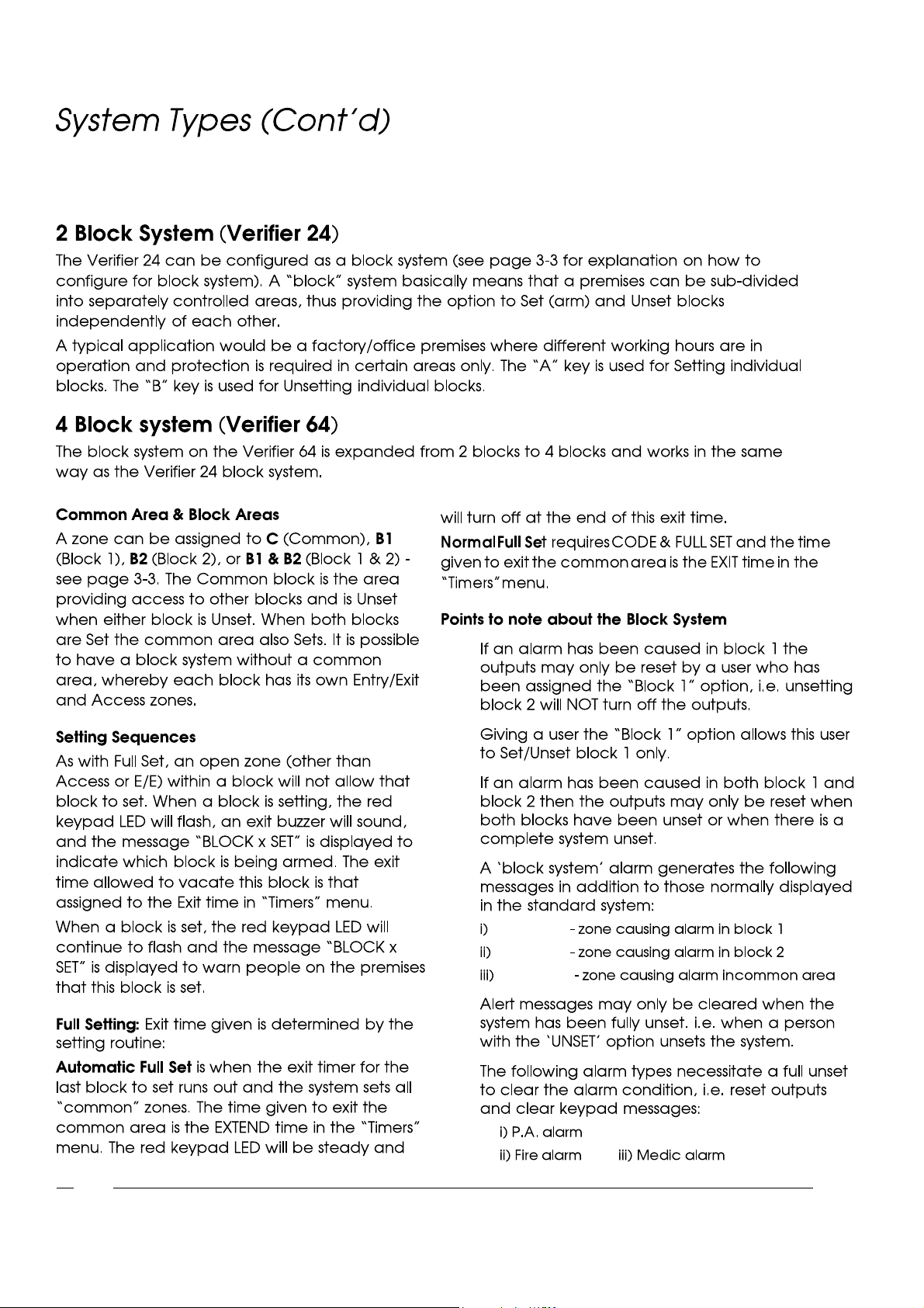
*BLOCK 1*
*BLOCK 2*
*COMMON*
l
l
2-2
Page 24
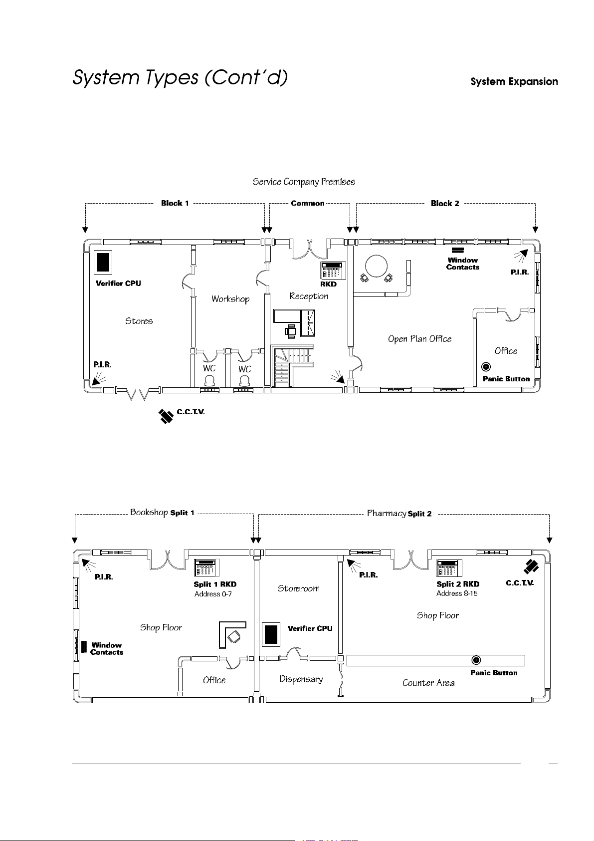
Fig. 10 - Block System
Fig. 11 - Split System
2-3
Page 25

System ExpansionSystem Expansion
l
l
l
l
l
l
l
l
l
2-4
Page 26
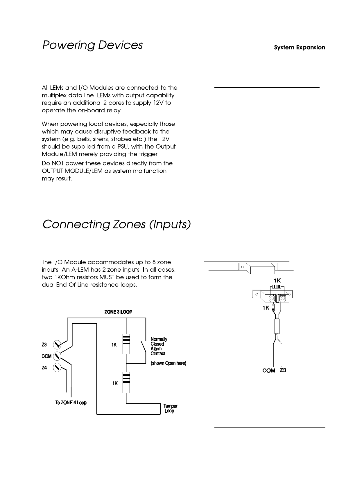
NOTE: If an Output Device is located
away from the panel, it should
be powered from a separate
Power Supply Unit with 0V of
the PSU connected to 0V of
the panel.
Fig. 12 - Connecting Zones
NOTE: After adding zones to the
system,the engineer must select
"RESET PANEL" from the
"Utilities"menu (p.3-10)so that
the system recognisesthe zones.
2-5
Page 27
I
n
p
u
t
/
O
u
t
p
u
t
M
o
d
u
l
e
N
/
O
C
-
L
E
M
O
u
t
p
u
t
O
u
t
p
u
t
s
(
2
o
r
4
p
e
r
M
o
d
u
l
e
)
N
/
C
Z
o
n
e
I
n
p
u
t
s
(
2
p
e
r
A
-
L
E
M
)
Z
o
n
e
I
n
p
u
t
s
(
8
p
e
r
M
o
d
u
l
e
)
T
a
m
p
e
r
Z
1
C
Z
2
Z
3
C
Z
4
Z
5
C
Z
6
Z
7
C
Z
8
L
E
M
G
N
D
C
T
L
D
A
T
A
G
N
D
T
X
R
X
E
X
T
B
E
L
L
-
+
I
N
T
B
E
L
L
-
+
A
U
X
2
-
1
2
V
+
0
1
0
2
0
3
0
4
A
U
X
1
-
1
2
V
+
-
V
E
H
O
L
D
T
A
M
P
R
E
T
A
-
L
E
M
LEM GROUND
1
K
1
K
1
K
1
K
1
K
1
K
1
K
1
K
1
2
V
0VD
A
T
A
C
O
N
T
R
O
L
L
E
M
G
R
O
U
N
D
C
-
L
E
M
N
/
O
N
/
C
H
a
r
d
w
i
r
e
d
Z
o
n
e
I
n
p
u
t
s
(
m
a
x
8
)
CONTROL
DATA
OV
12V
System ExpansionSystem Expansion
1K
1K1K
2-6
MDG
CONTROL
DATA
0V
12V
1K
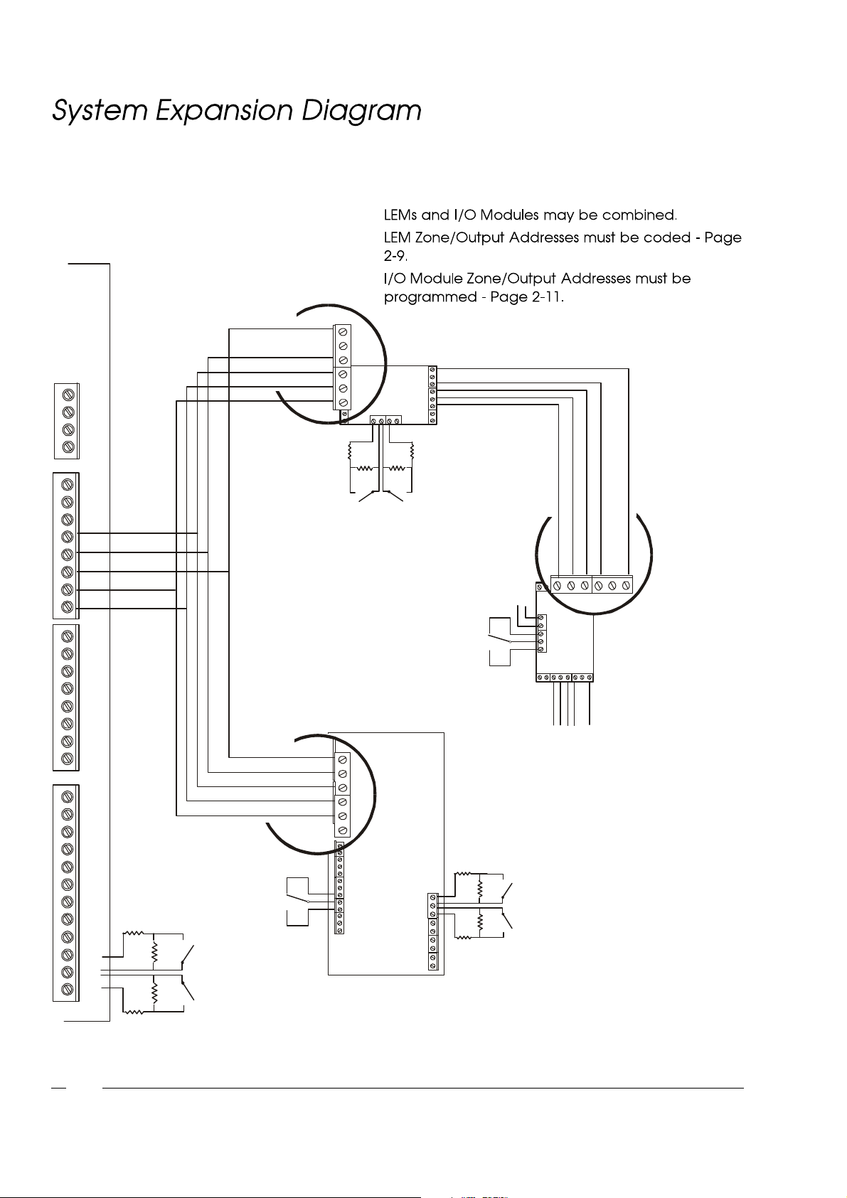
Fig. 13 - System Expansion
Page 28
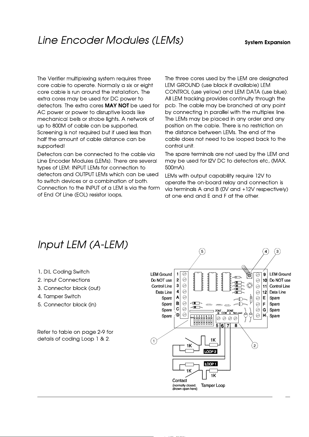
Fig. 14 - Input LEM (A-LEM)
2-7
Page 29
System ExpansionSystem Expansion
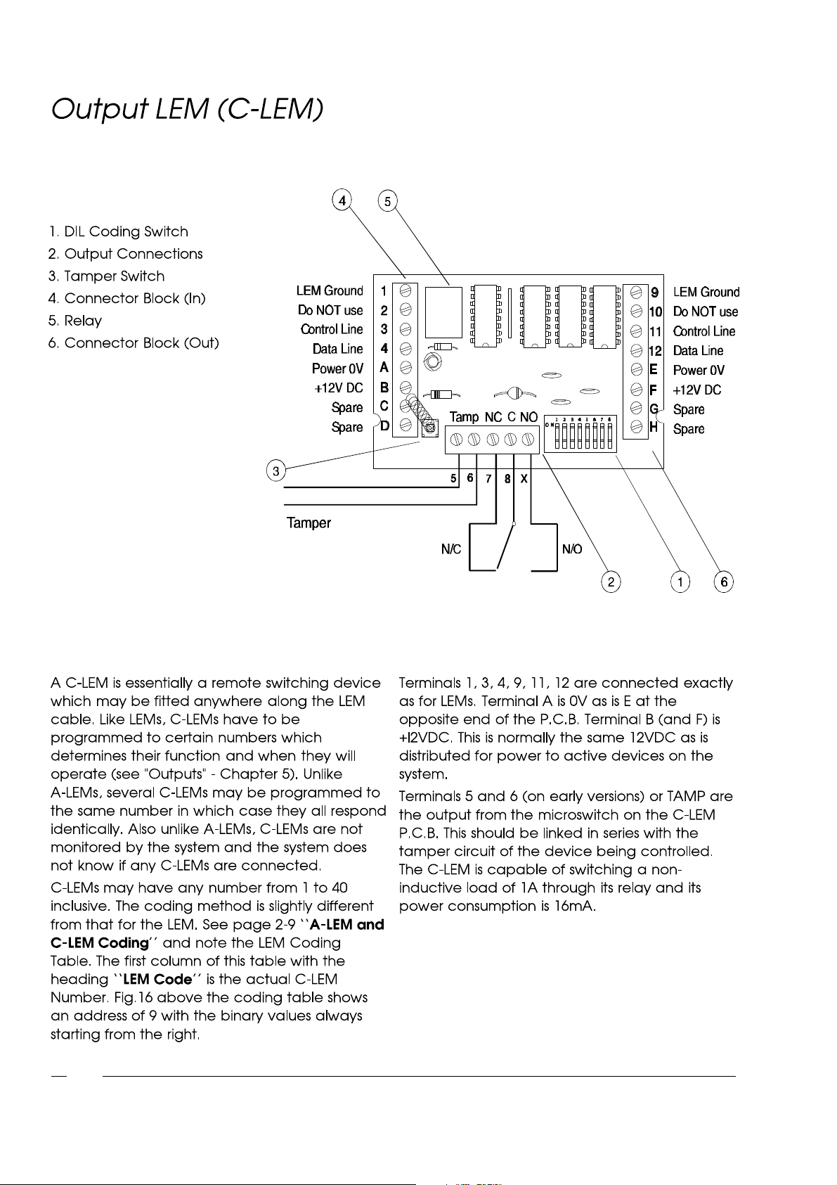
Fig. 15 - Output LEM (C-LEM)
2-8
Page 30
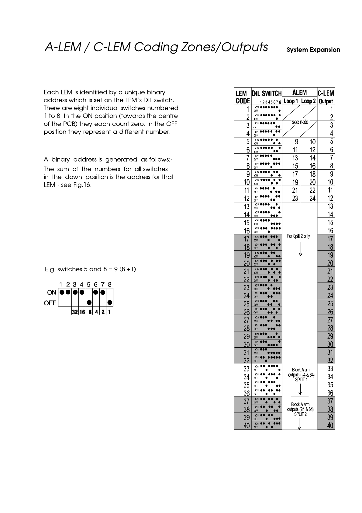
NOTE: Zones 1 to 8 are on-board and must
NOT be duplicated on the multiplex
data line via LEMs or I/O Modules.
Duplicated zones will not be
recognisedby the system.
Fig. 16 - Binary AddressDIL Switch
Fig. 17 - LEM CodingTable
2-9
Page 31
System ExpansionSystem Expansion
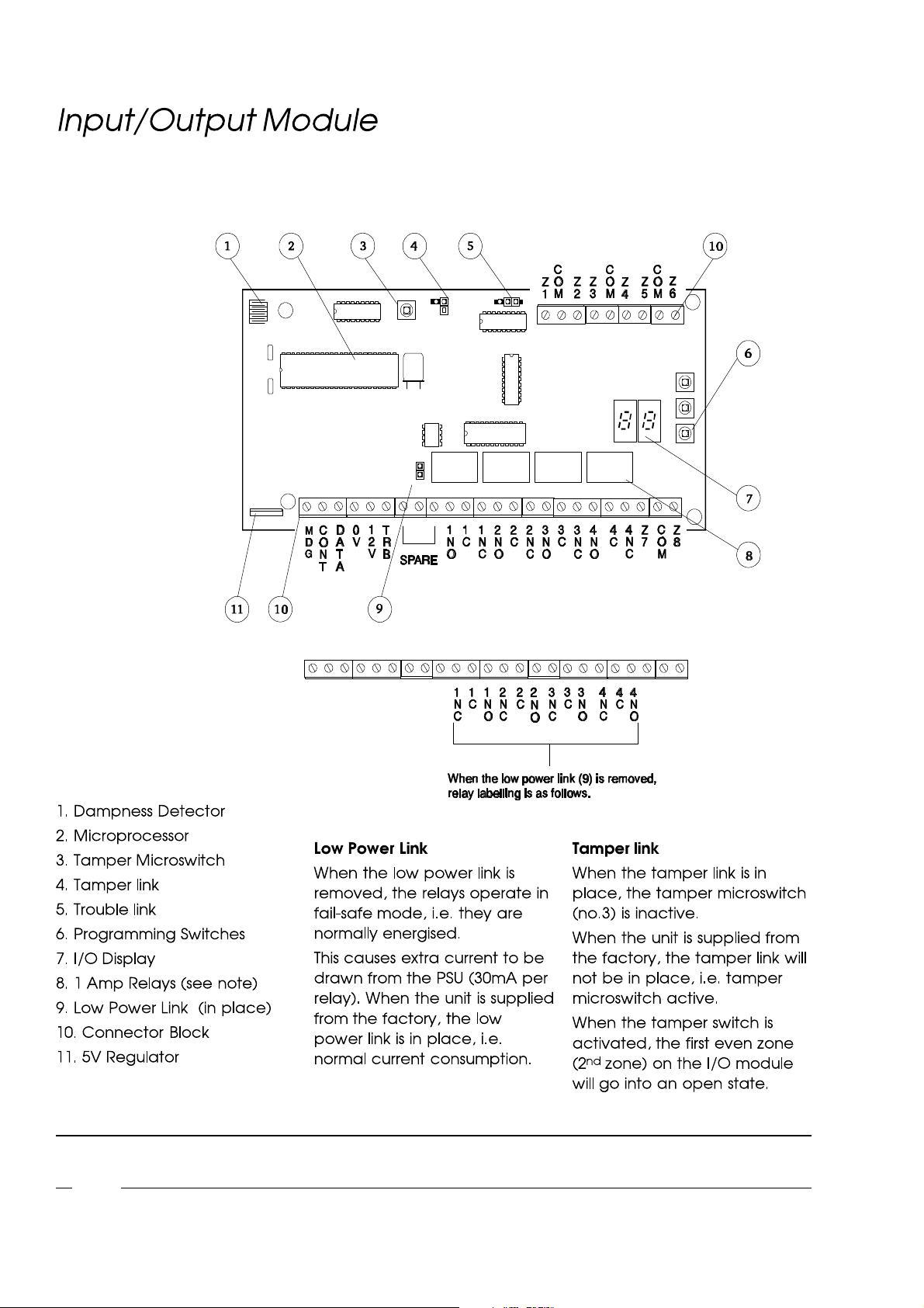
Fig. 18 - Input/OutputModule
NOTE: Input/Output Modules are available in two versions - 8 input / 4 output and 8 input / 2 output. The 4 output
(i.e. 4 relays) version is documented in this manual.
2-10
Page 32

2-11
Page 33
System ExpansionSystem Expansion
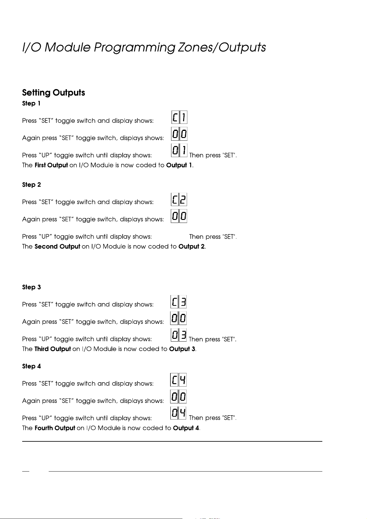
IMPORTANT: Zone addressesMUST NOT be duplicated. The system will NOT allow pairs of zones to have the same
addresson an I/O Module. Different I/O Modules must not have the same address settings. If this happens
offending zone addresses will not initialize. Output addressesmay be duplicated.
2-12
Page 34
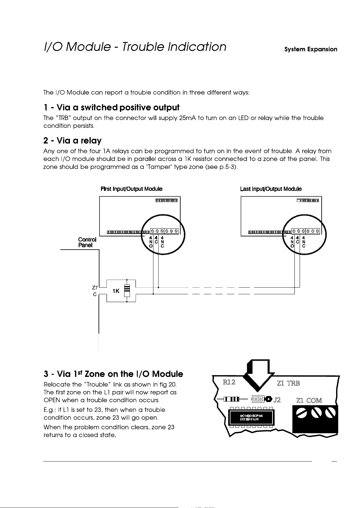
Fig. 19 - Trouble Indicationvia a relay
Fig. 20 - Trouble Indicationvia first zone
2-13
Page 35

System ExpansionSystem Expansion
NOTE: The removal of any I/O module lid will activate the tamper switch and cause the second zone on the I/O
module to go open. E.g. on an I/O module with zones programmed 9 to 16, zone 10 goes open.
2-14
Page 36

ChapterThree
Page 37
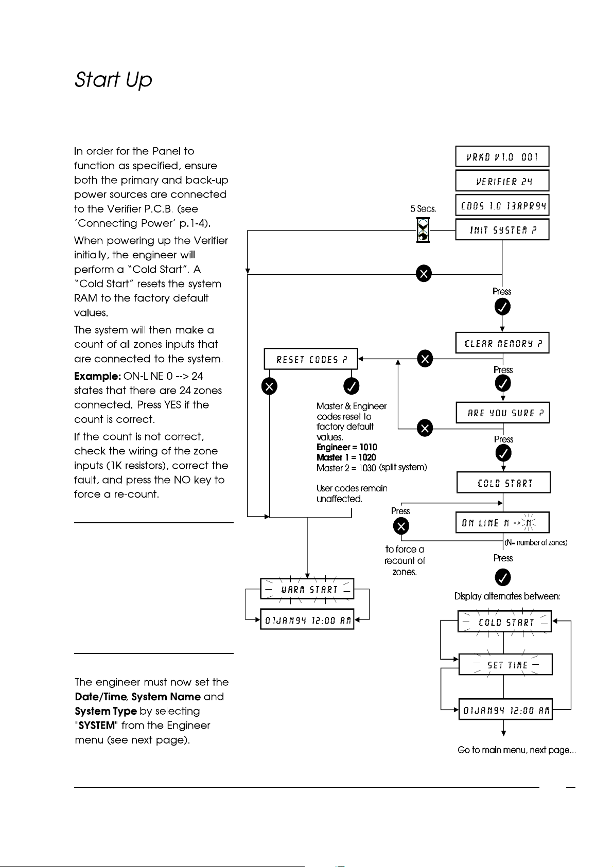
Engineer Menu
NOTE: If the zone count is still
incorrect,press the YES
key and select "Single
Zone Monitor" from the
"Utilities"menu (p.3-10).
This option allows the
engineer to analyse the
status of the zones.
3-1
Page 38
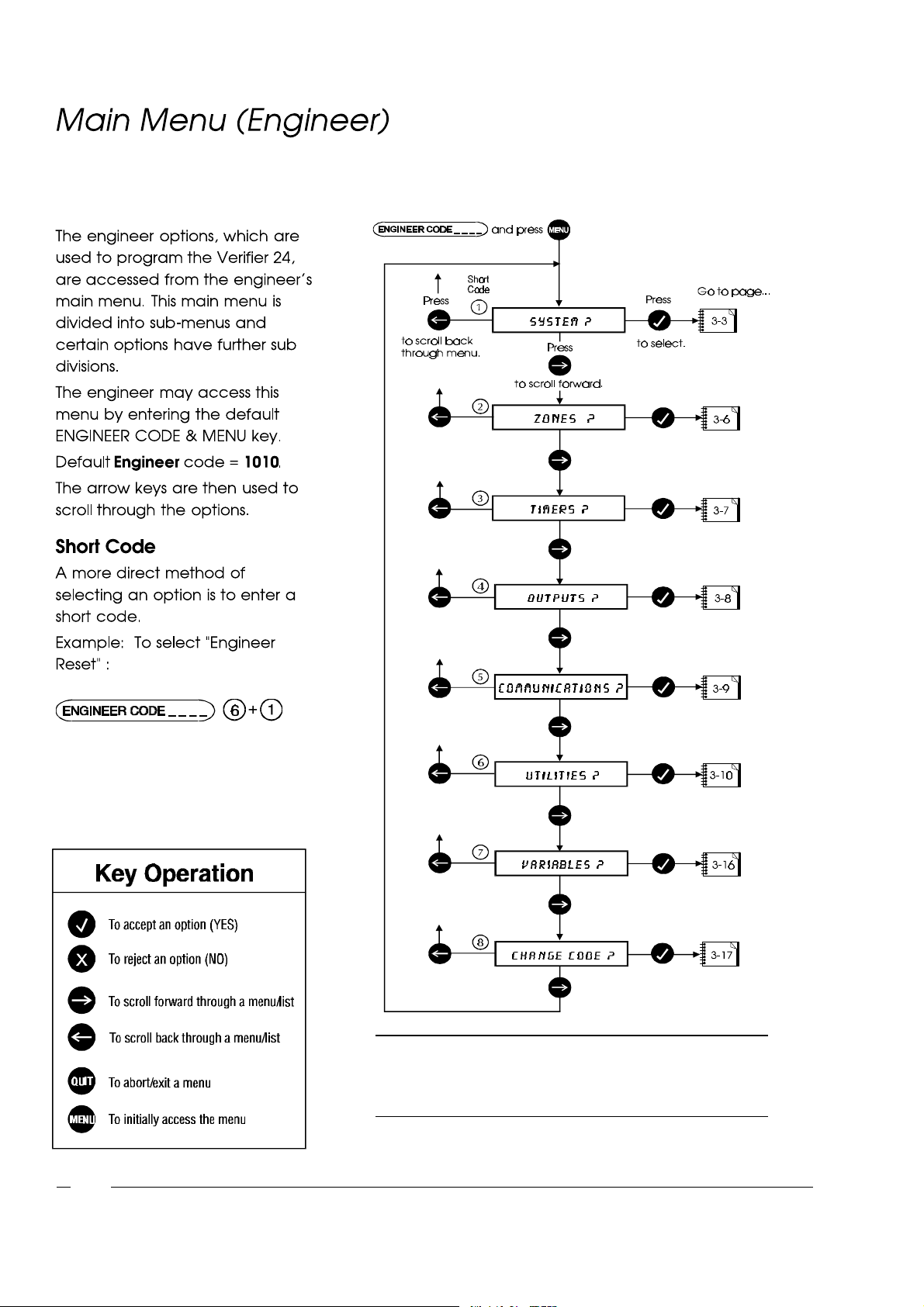
Engineer Menu
3-2
NOTE All tamper circuits are disabled when engineer mode is
entered. This includes all zone and system tampers
(cabinet tamper, PA, Fire etc.)
Page 39
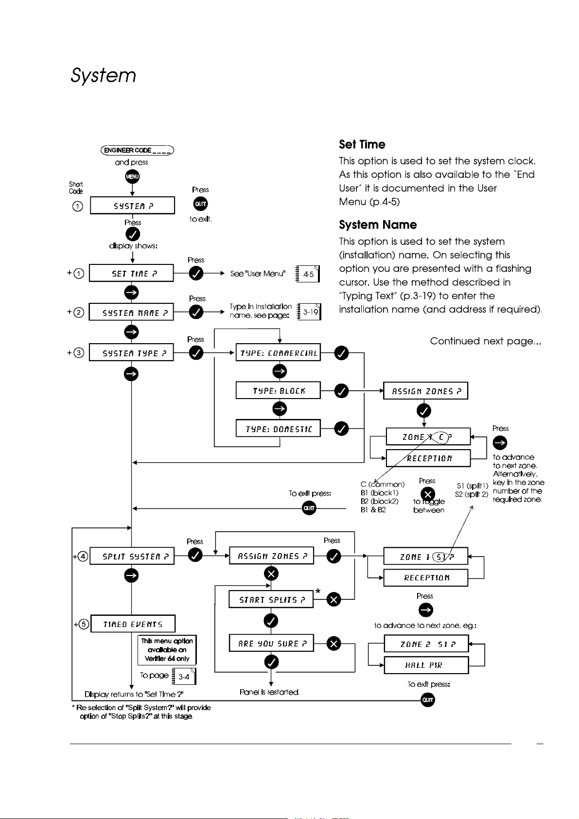
Engineer Menu
3-3
Page 40
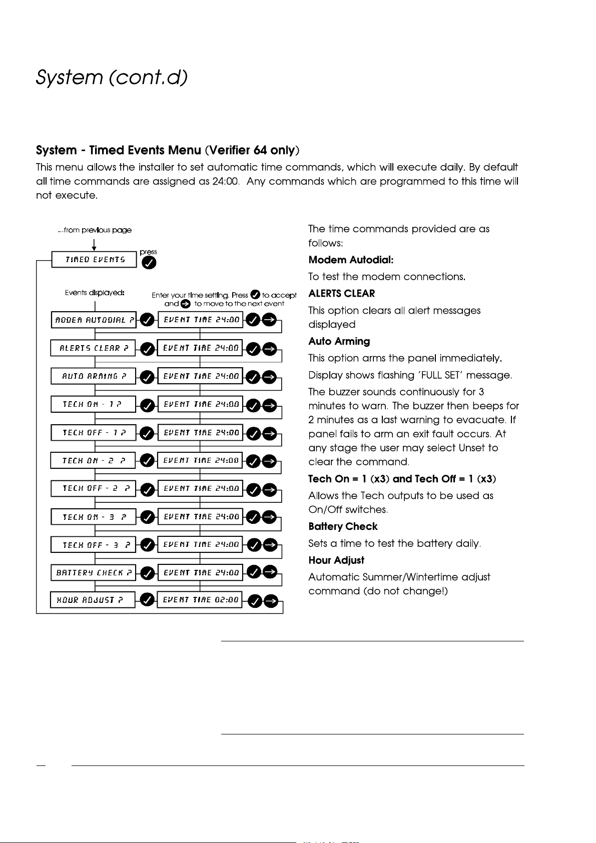
Engineer Menu
3-4
Note i) No two time commands may be set to the same time(only one
will be executed).
ii) Time commands are not split specific, i.e. if in split mode then
setting the Alert Accept time command for 1:00 will cause alerts to
be cleared on both splits at that time.
Page 41
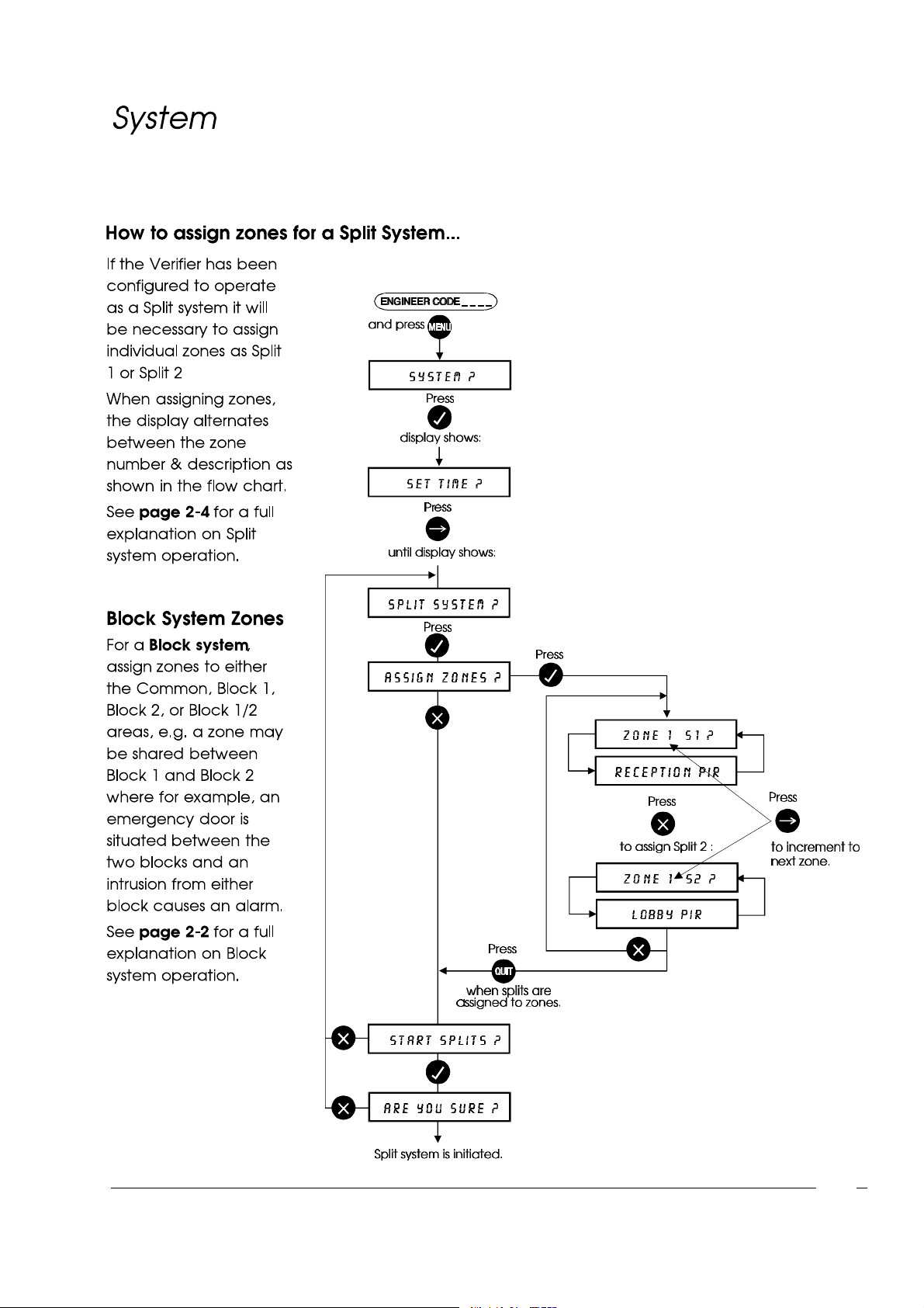
Engineer Menu
3-5
Page 42
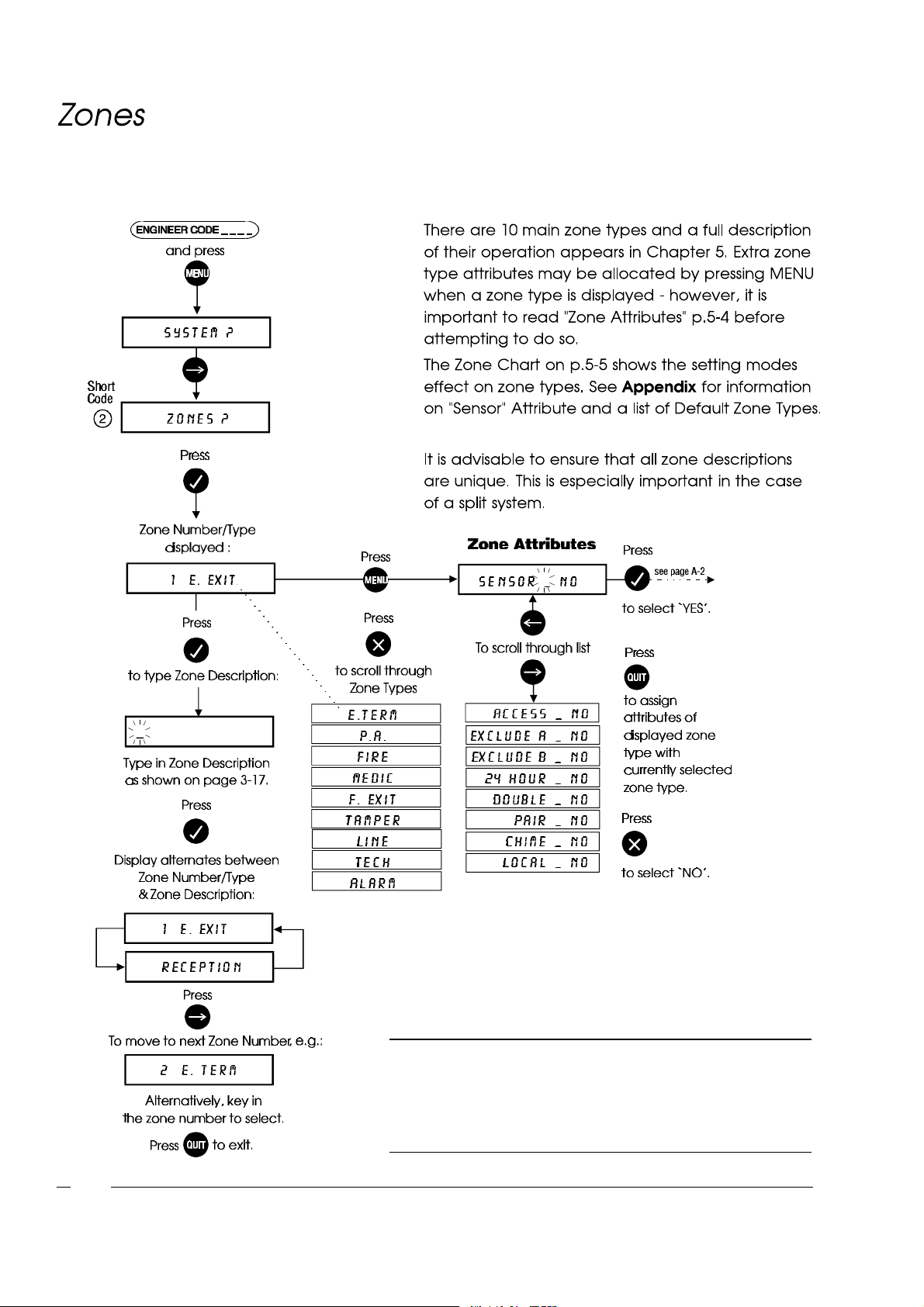
Engineer Menu
3-6
WARNING! Assigning "Attributes"will radically alterthe behaviour
of zone types and therefore it is essential to be familiar
with the consequencesof such action. See "Zone
Attributes"on page 5-4 for a full explanation.
Page 43
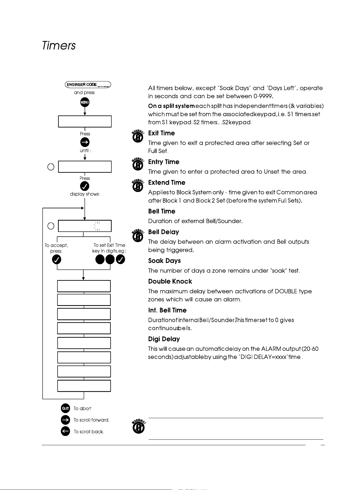
Short
Code
3
Engineer Menu
S Y ST E M ?
T IMERS ?
+
1
E XI T T IME 3 0
5 5
9
e n t r y T IME 3 0
EXT E N D T I ME 3 0
BE L L T I ME 1 2 0 0
BE LL D EL AY 1
S OA K D A Y S 7
DB L K N OC K 3 0
I . BEL L t i me 0
DI GI D EL A Y 2 0
7
Note: Certain timers are countdown timers whereby entering a value of 0 will
give an infinite time! Timers highlighted with a warning symbol must NOT
be set to zero.
3-7
Page 44
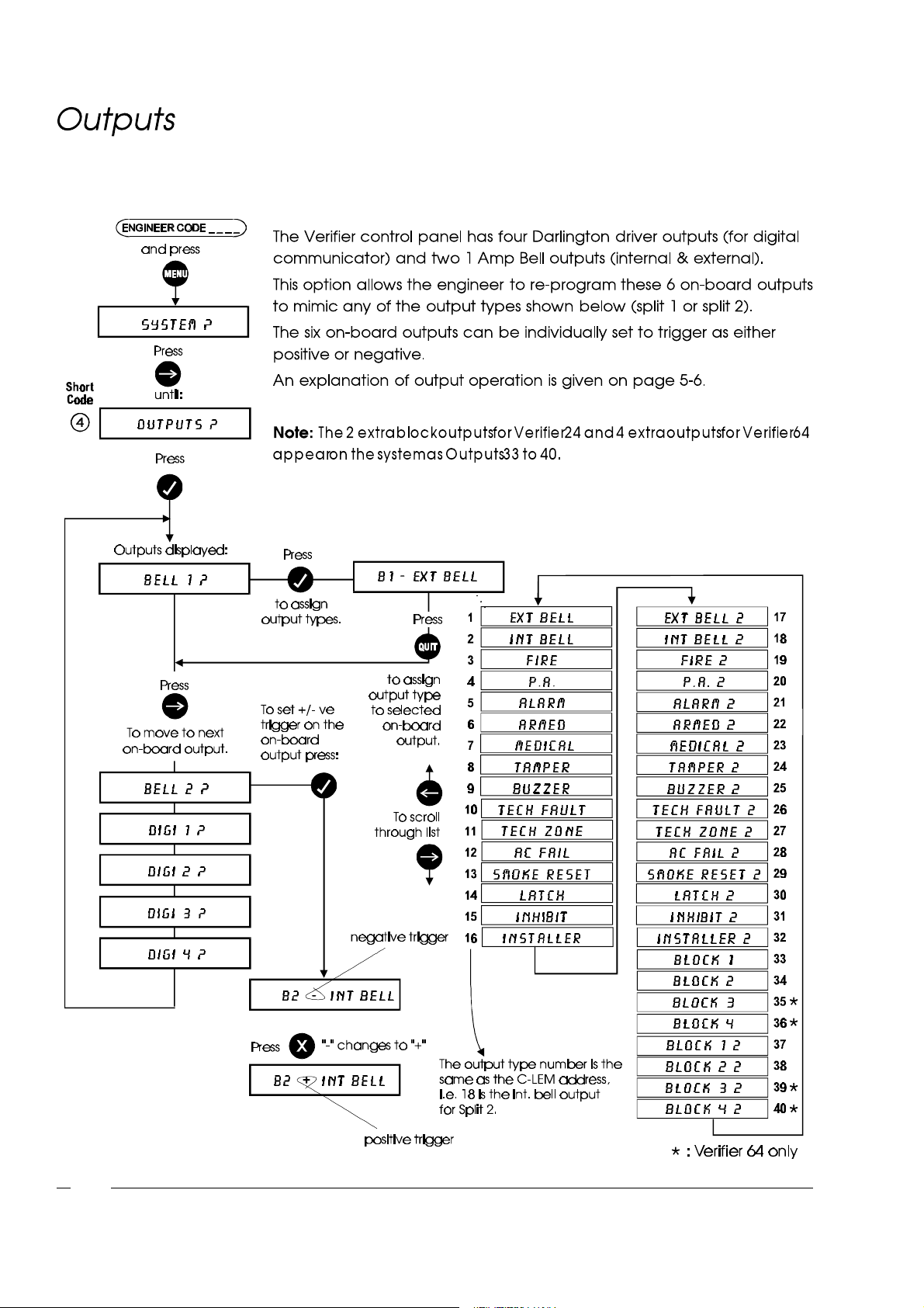
Engineer Menu
3-8
Page 45
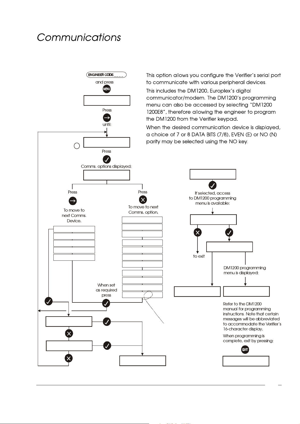
SYSTEM ?
Short
Code
COMMUNICATIONS ?
5
Engineer Menu
PANELMAN 2400E8
PRINTER
CUSTOM
NETWORK
DM1200
FILESAVER
DM1200 1200E8
1200 E 8
300 E 8
150 E 8
2400 E 7
1200 E 7
300 E 7
150 E 7
2400 N 8
1200 N 8
300 N 8
150 N 8
SET UP DM1200 ?
CHECKING
NO RESPONSE
DM1200
PRINT REPORTS ?
PRINT LOG ?
PRINTING
E = Even Parity
N= No Parity
7 = 7 Data Bits
8 = 8 Data Bits
END
3-9
Page 46
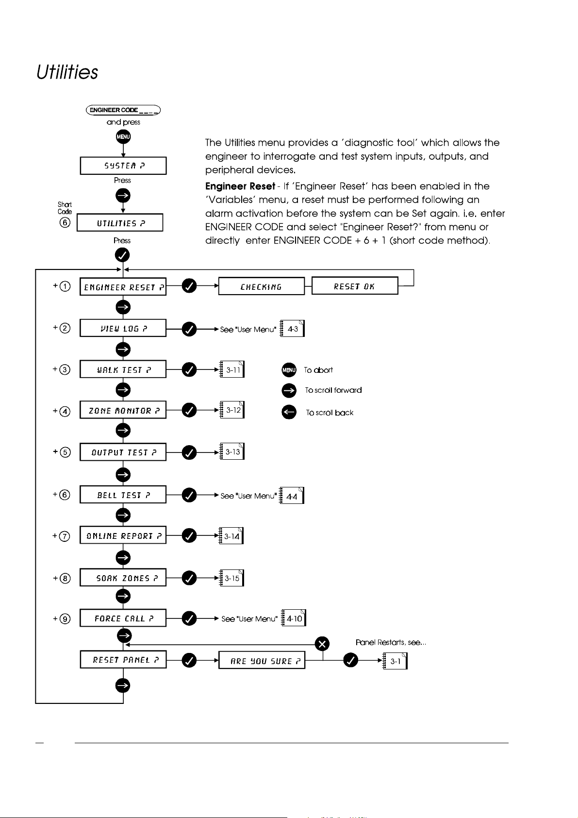
Engineer Menu
3-10
Page 47
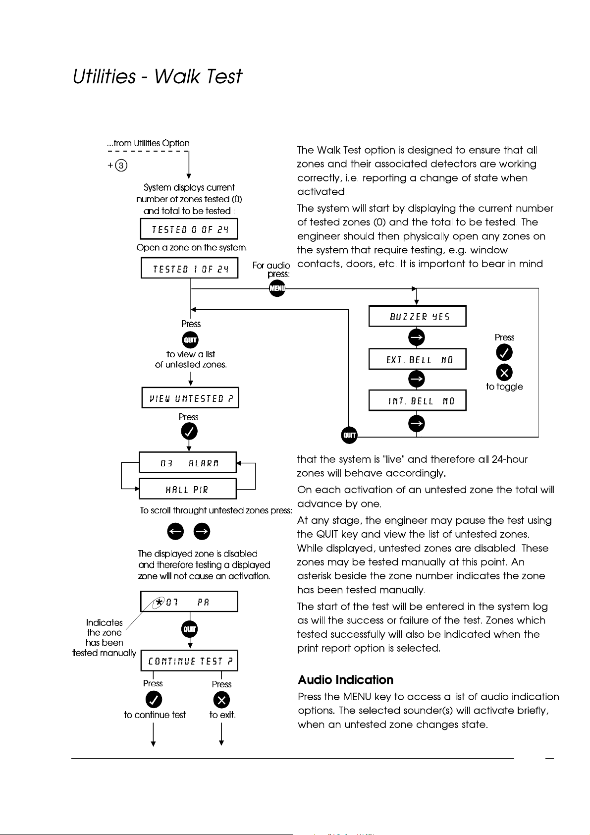
Engineer Menu
3-11
Page 48
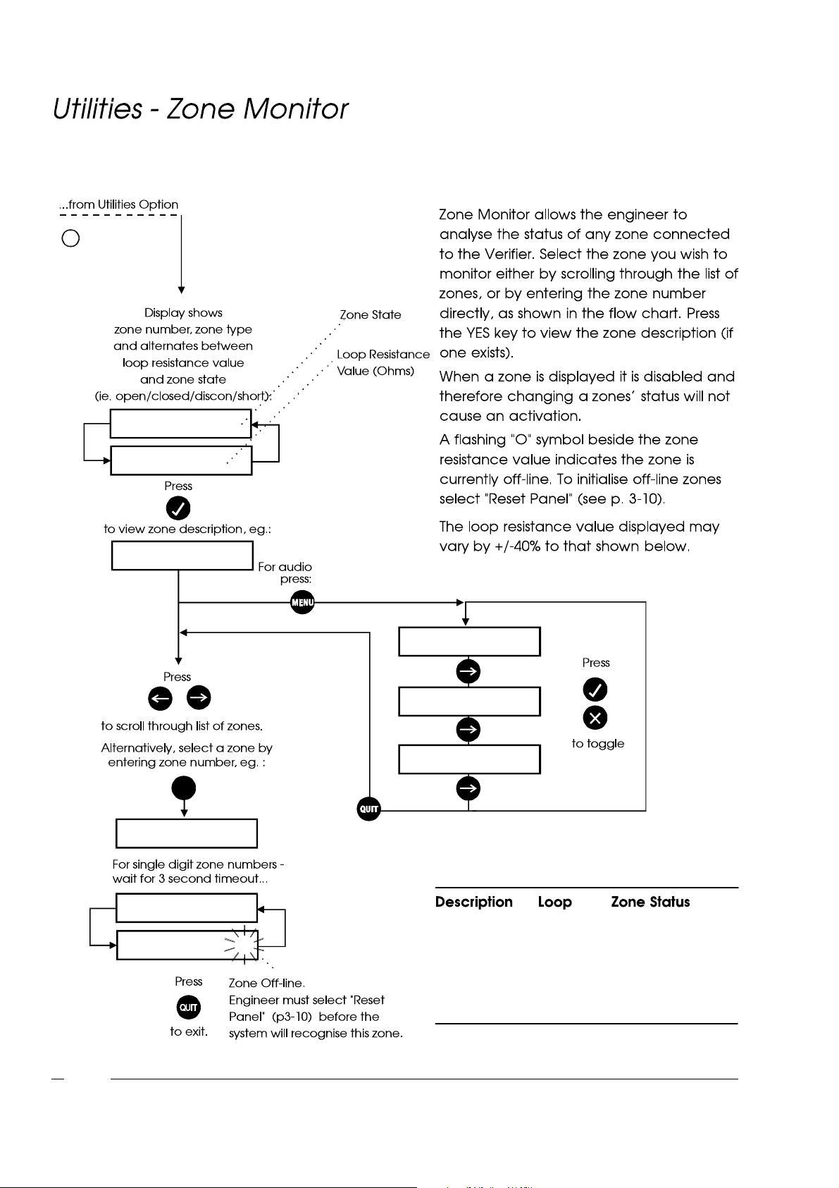
Engineer Menu
+
4
0 1 E .EXI T C L O S E D
0 1 E .EXI T 1 0 0 0
F R O N T D OOR
9
E N T E R Z O N E 9 _
0 9 A L A R M OP EN
0 9 A L A R M 2 0 0 0 O
BU Z Z E R Y E S
E XT. B EL L N O
I N T . B E L L N O
W
OPEN 2000 Zone Open
CLOSED 1000 Zone Closed
3-12
DISCON 9999 Zone Disconnected
SHORT 0 Zone Shorted
Page 49
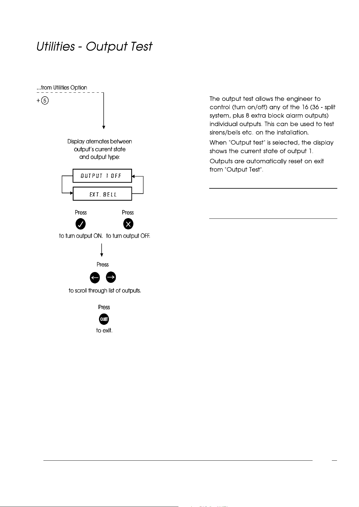
Engineer Menu
NOTE: When testing outputs it is important to
be aware that certain outputs will trigger
a digital communicator.
3-13
Page 50
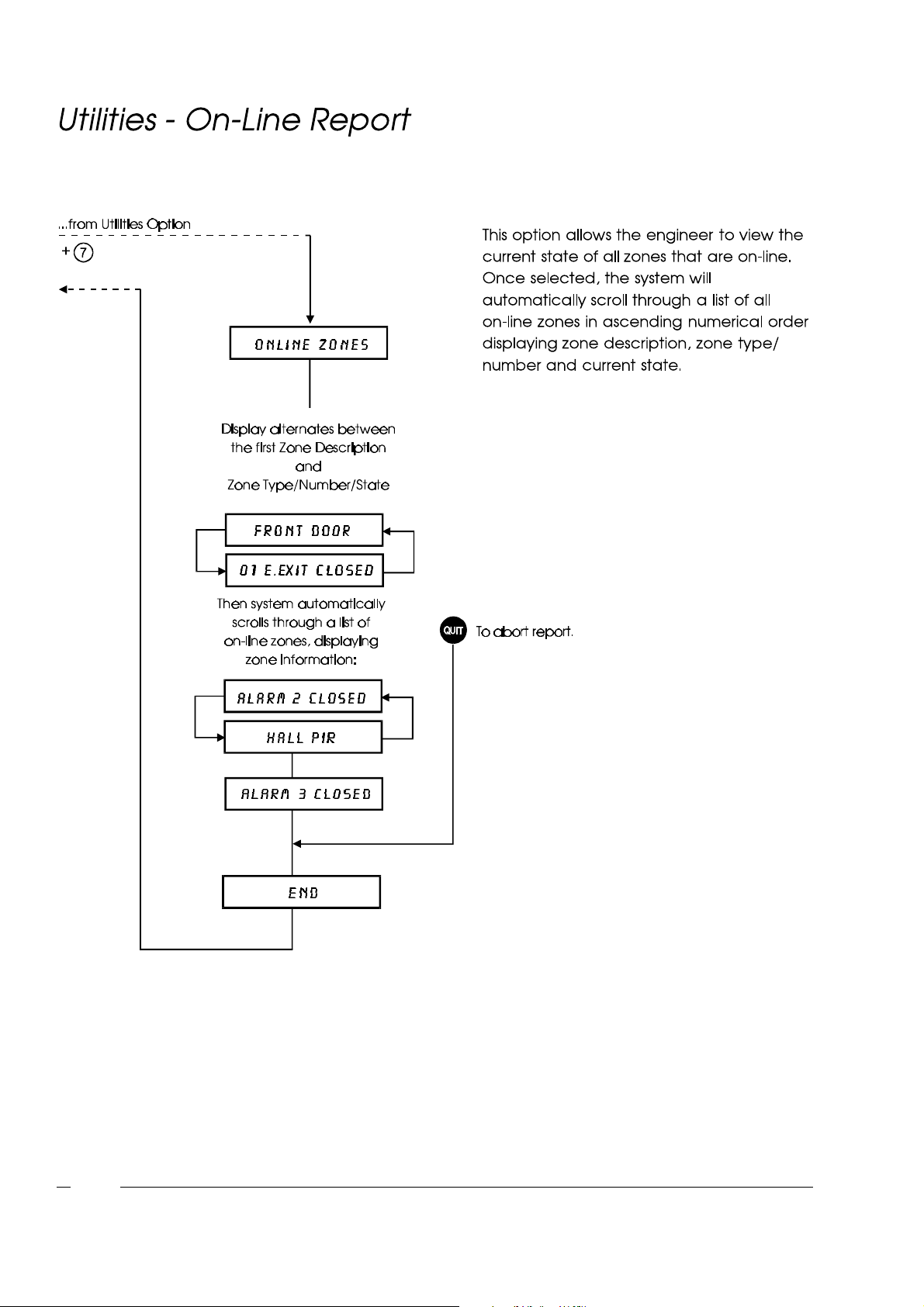
Engineer Menu
3-14
Page 51
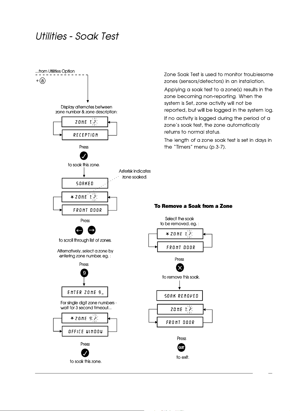
Engineer Menu
3-15
Page 52
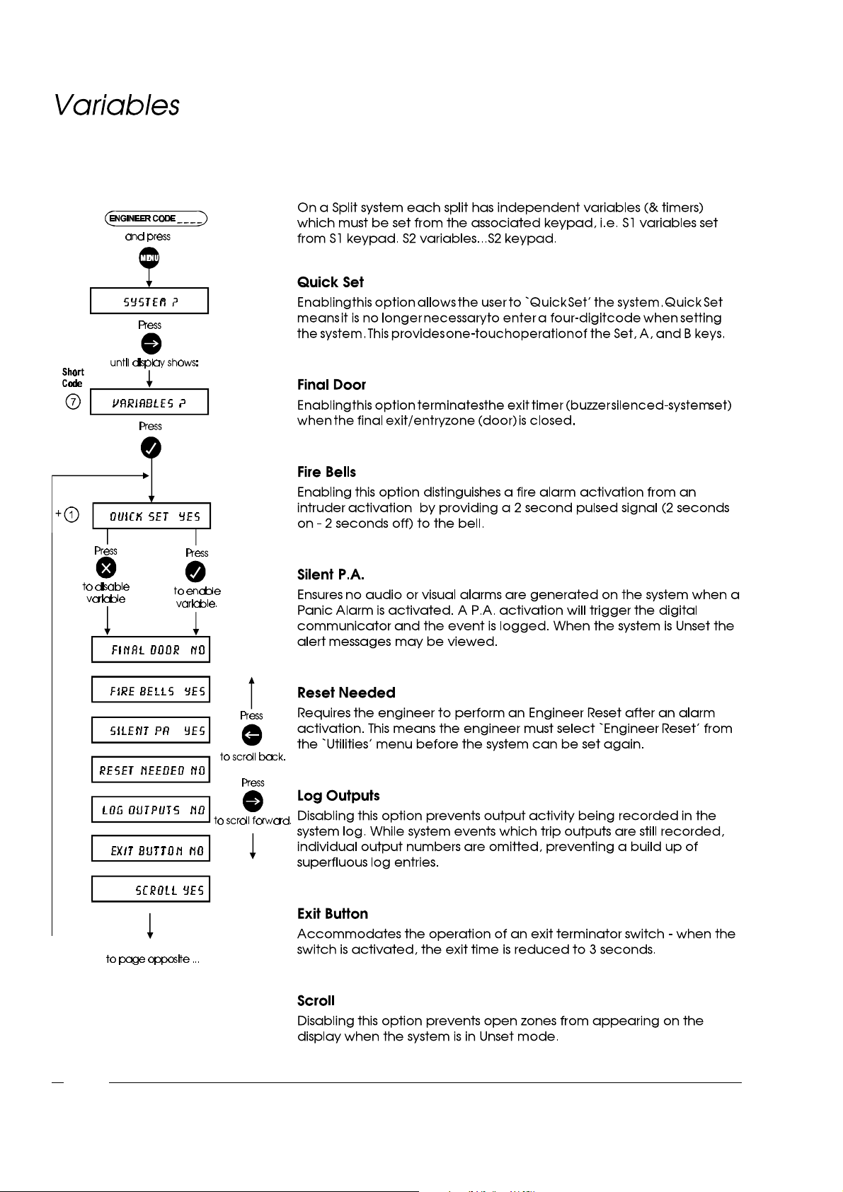
Engineer Menu
3-16
Page 53
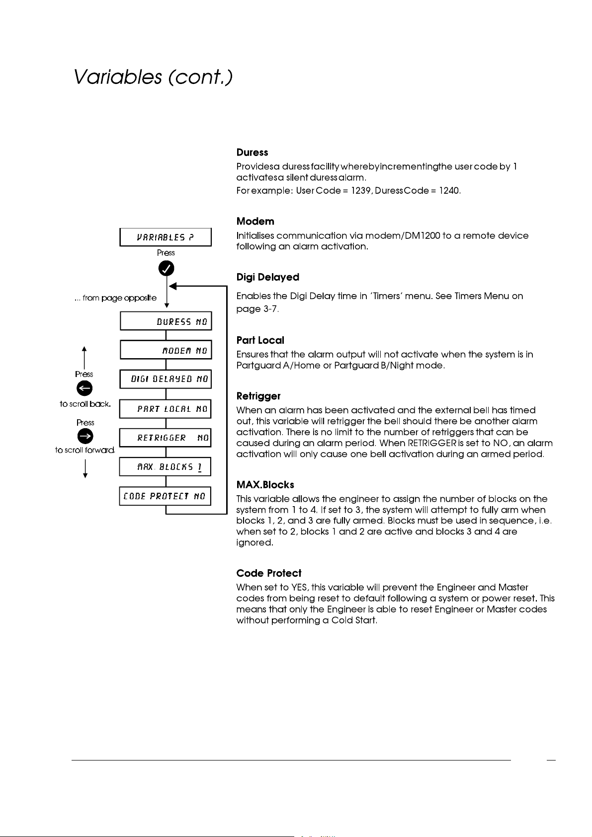
Engineer Menu
(VERIFIER(VERIFIER 6464 ONLY)ONLY)
3-17
Page 54
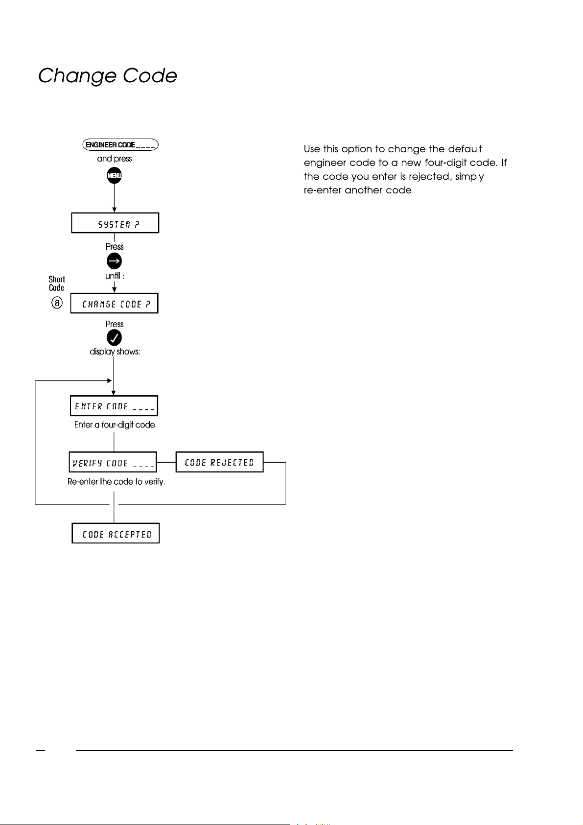
Engineer Menu
3-18
Page 55
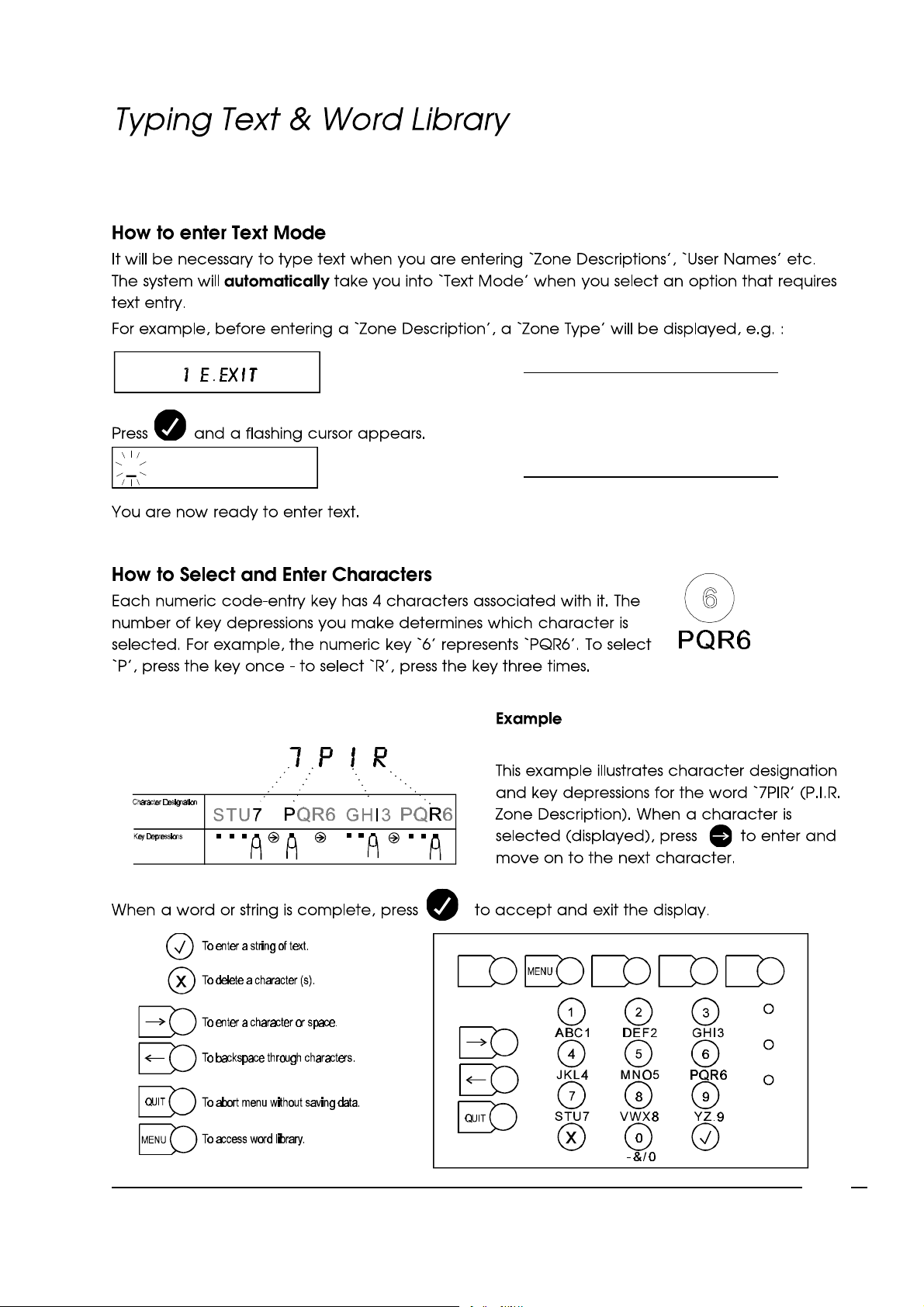
NOTE: See appendix for list of
words available in word
library - see overleafon how
to access word library.
Engineer Menu
3-19
Page 56
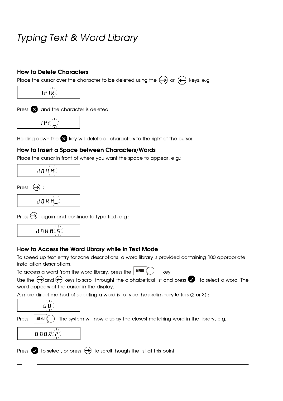
X
Engineer Menu
3-20
è ç
Page 57

Engineer Menu
3-21
Page 58

ChapterFour
Page 59
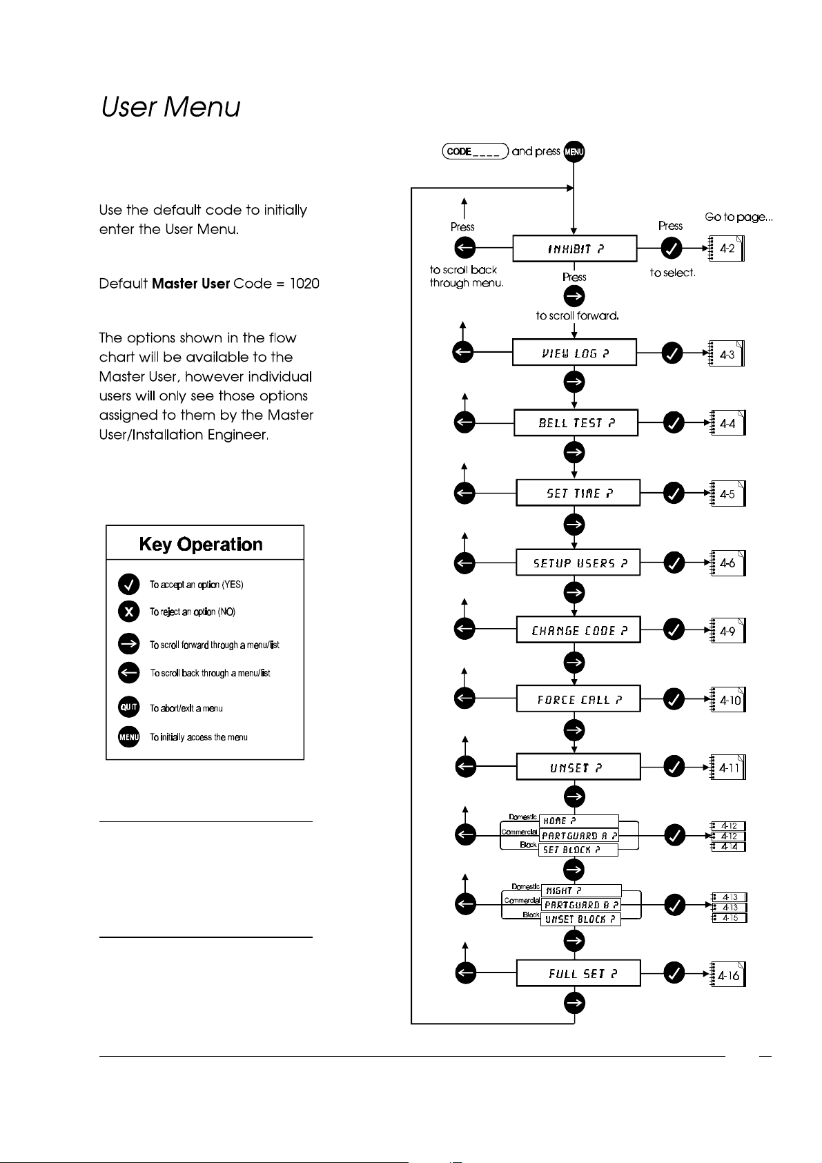
User Menu
NOTE:
Setting mode descriptions will differ
depending on the system type, i.e.
Commercial, Domestic, Block system.
4-1
Page 60
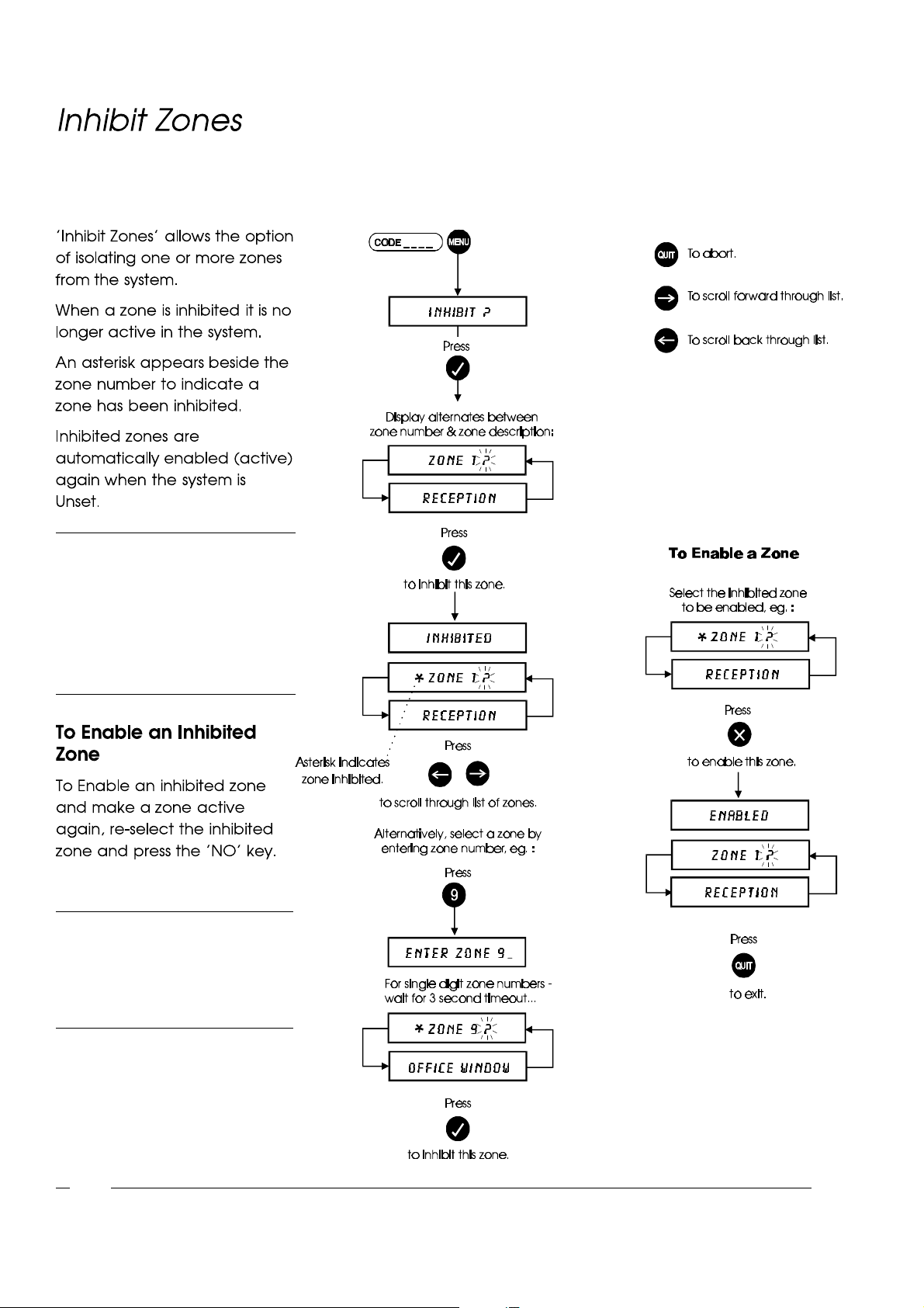
NOTE: Inhibit may be assigned to all
zone types except PANIC, MEDIC, and
FIRE. By default any other zone types
may be inhibited. The engineer must
set the attribute to NO to prevent it
being inhibited.
User Menu
NOTE: Quick Inhibit on Arming. This
option enables you to select zones to
inhibit while you are setting the
system. See Full Set on page 4-16.
4-2
Page 61
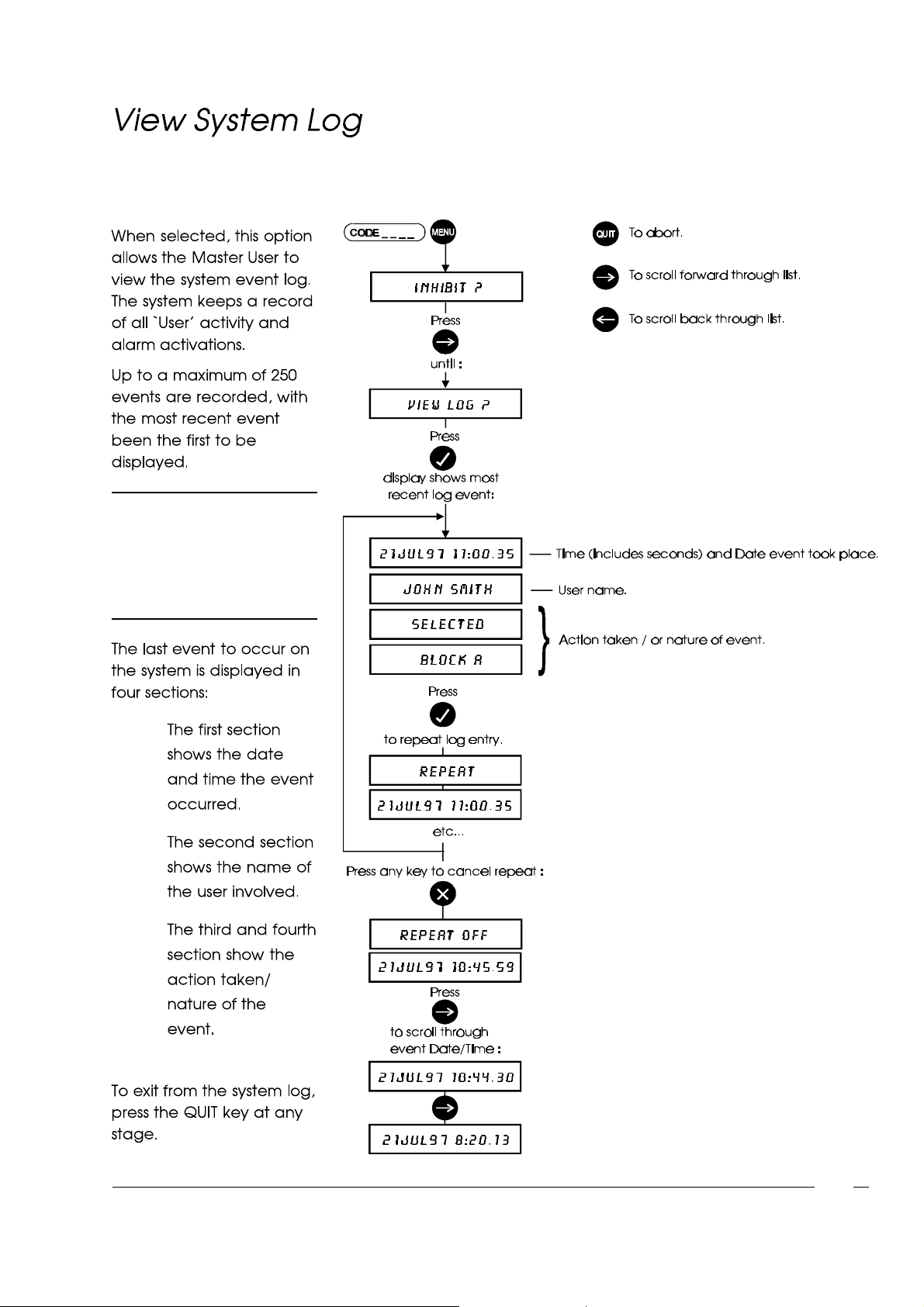
NOTE:
Verifier 64 systems allow for a
maximum of 500 events
recorded.
User Menu
l
l
l
4-3
Page 62
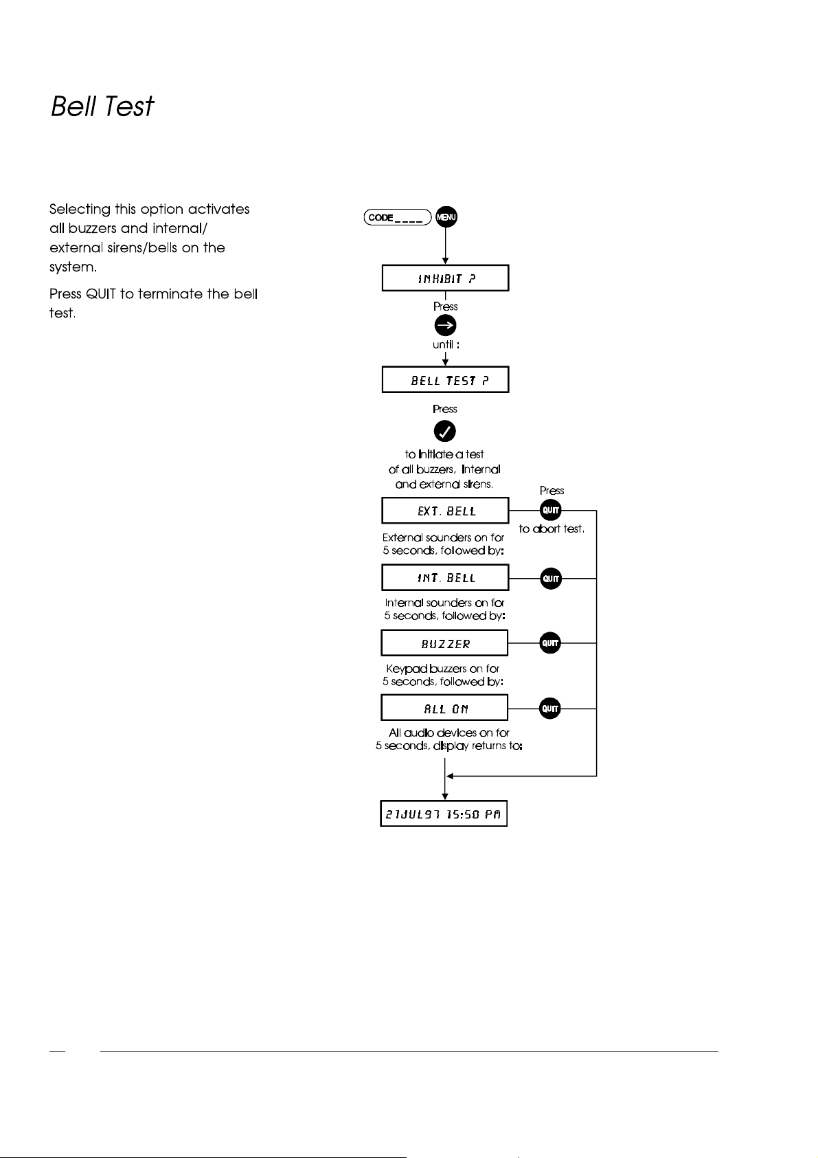
User Menu
4-4
Page 63
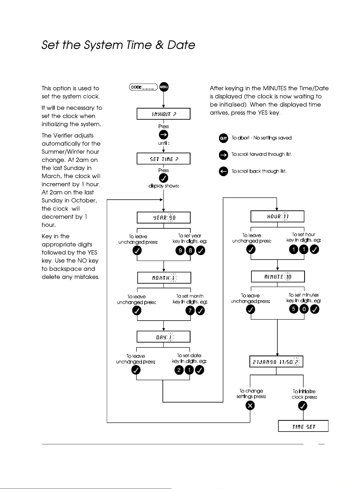
User Menu
On a split system
Date/Time may only be
set by users on Split 1.
4-5
Page 64
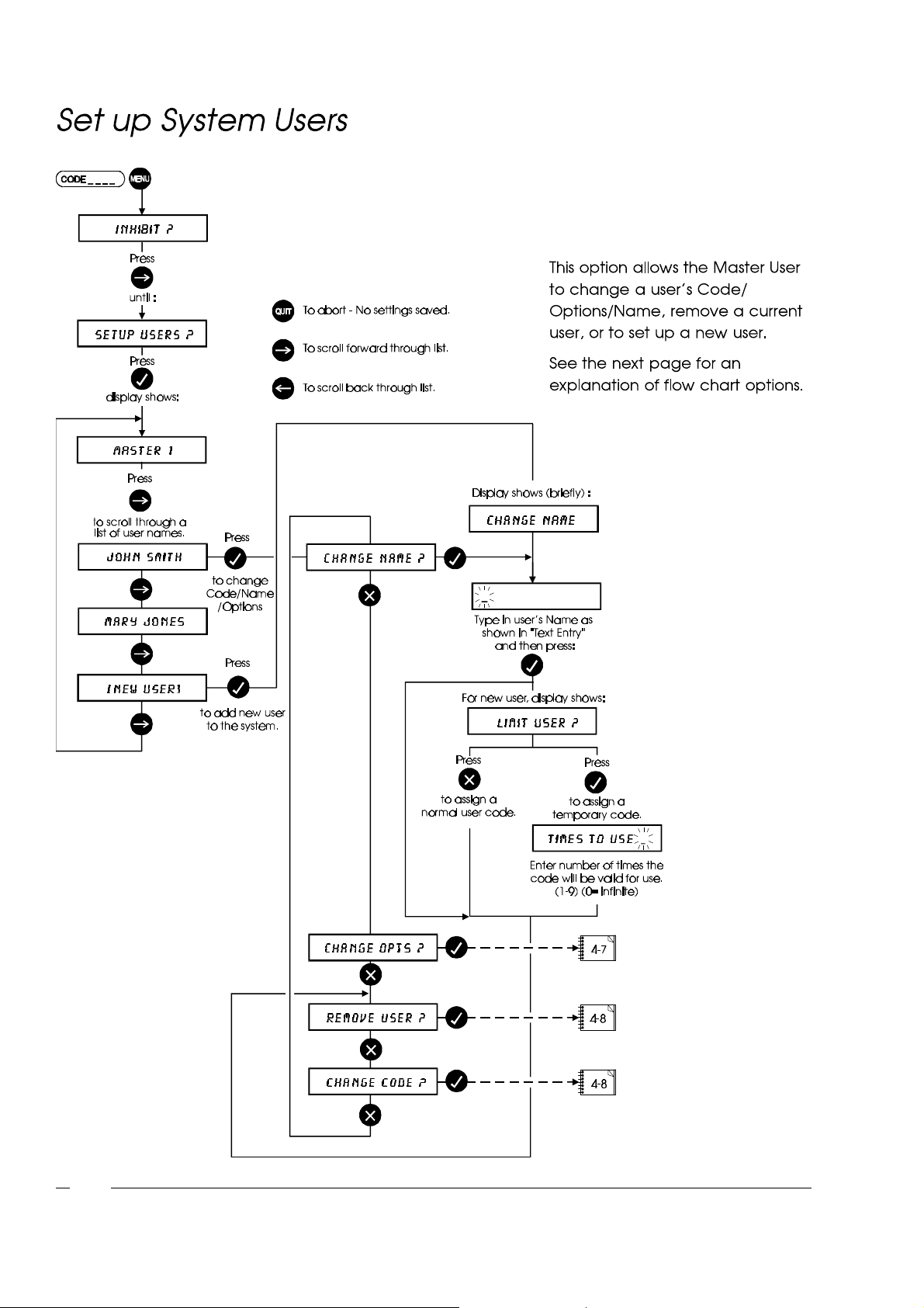
User Menu
4-6
Page 65
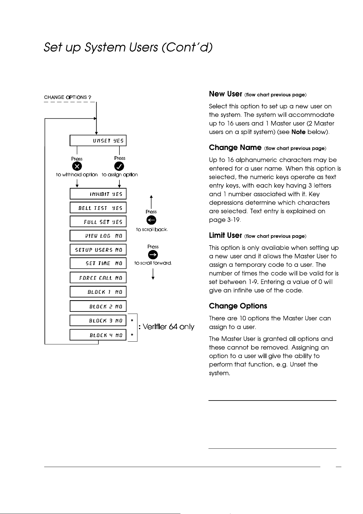
User Menu
NOTE:
Verifier 64 systems allow for up to 32 users with I
installer and 2 master codes (1 per split).
4-7
Page 66
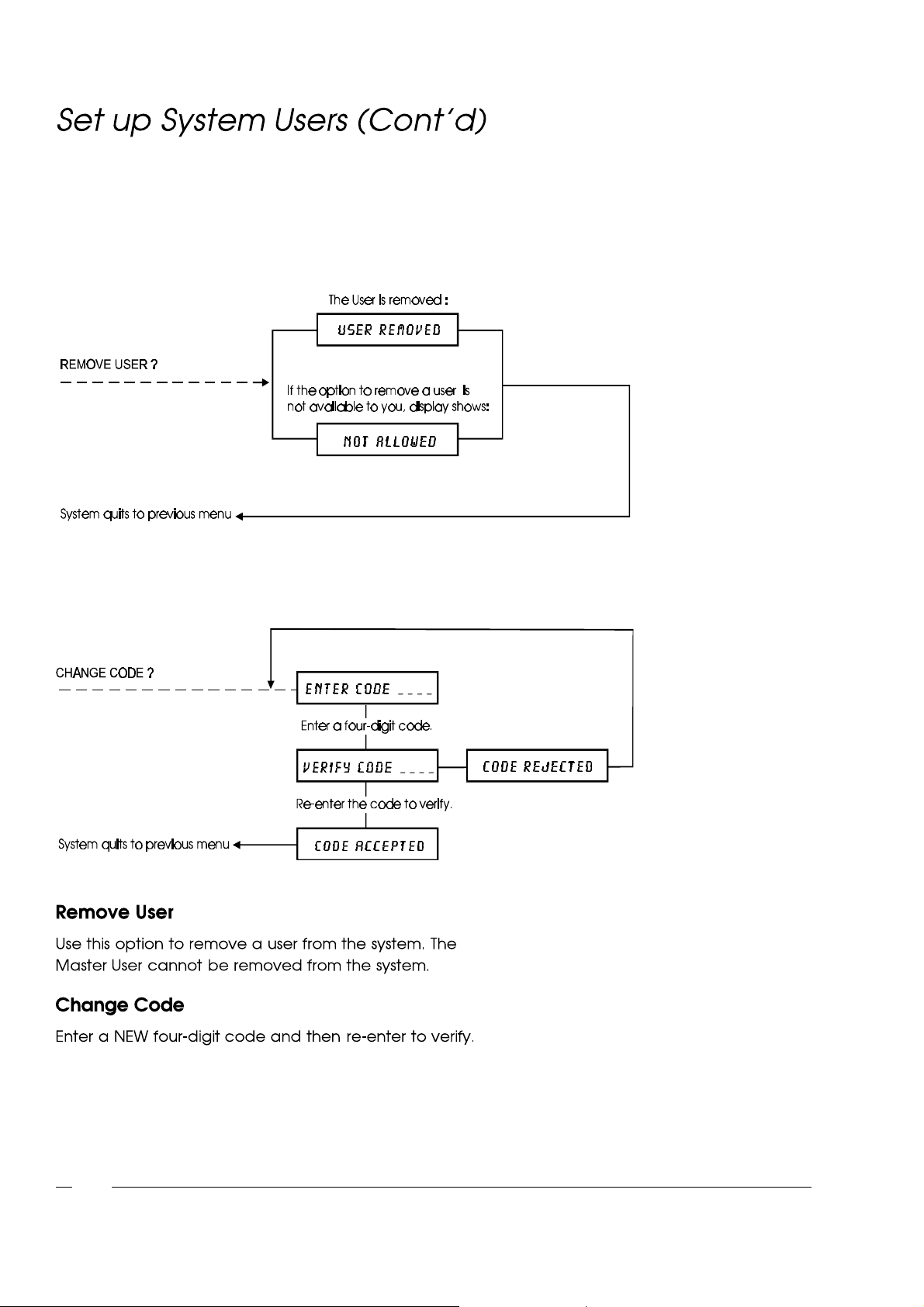
User Menu
4-8
Page 67
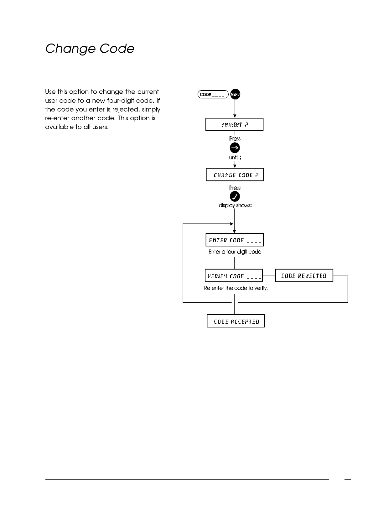
User Menu
4-9
Page 68
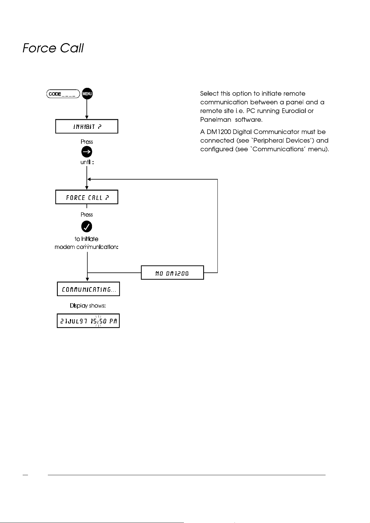
User Menu
4-10
Page 69
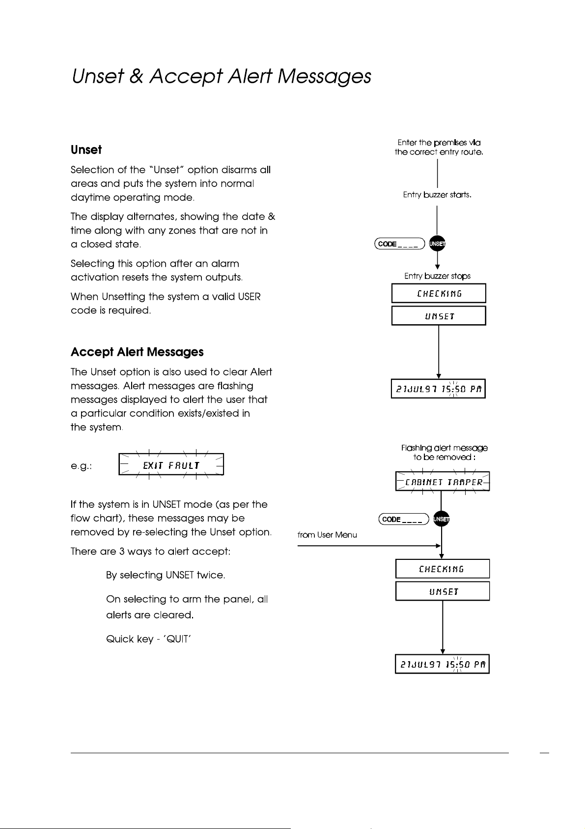
User Menu
l
l
l
4-11
Page 70
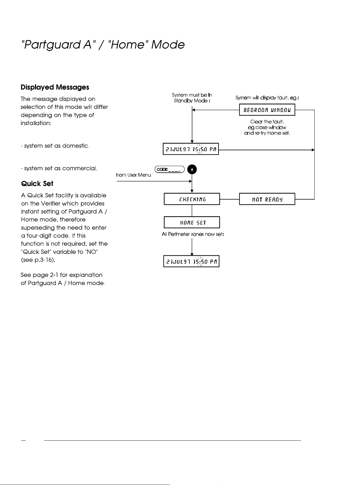
HOME ?
PARTGUARDA ?
User Menu
4-12
Page 71
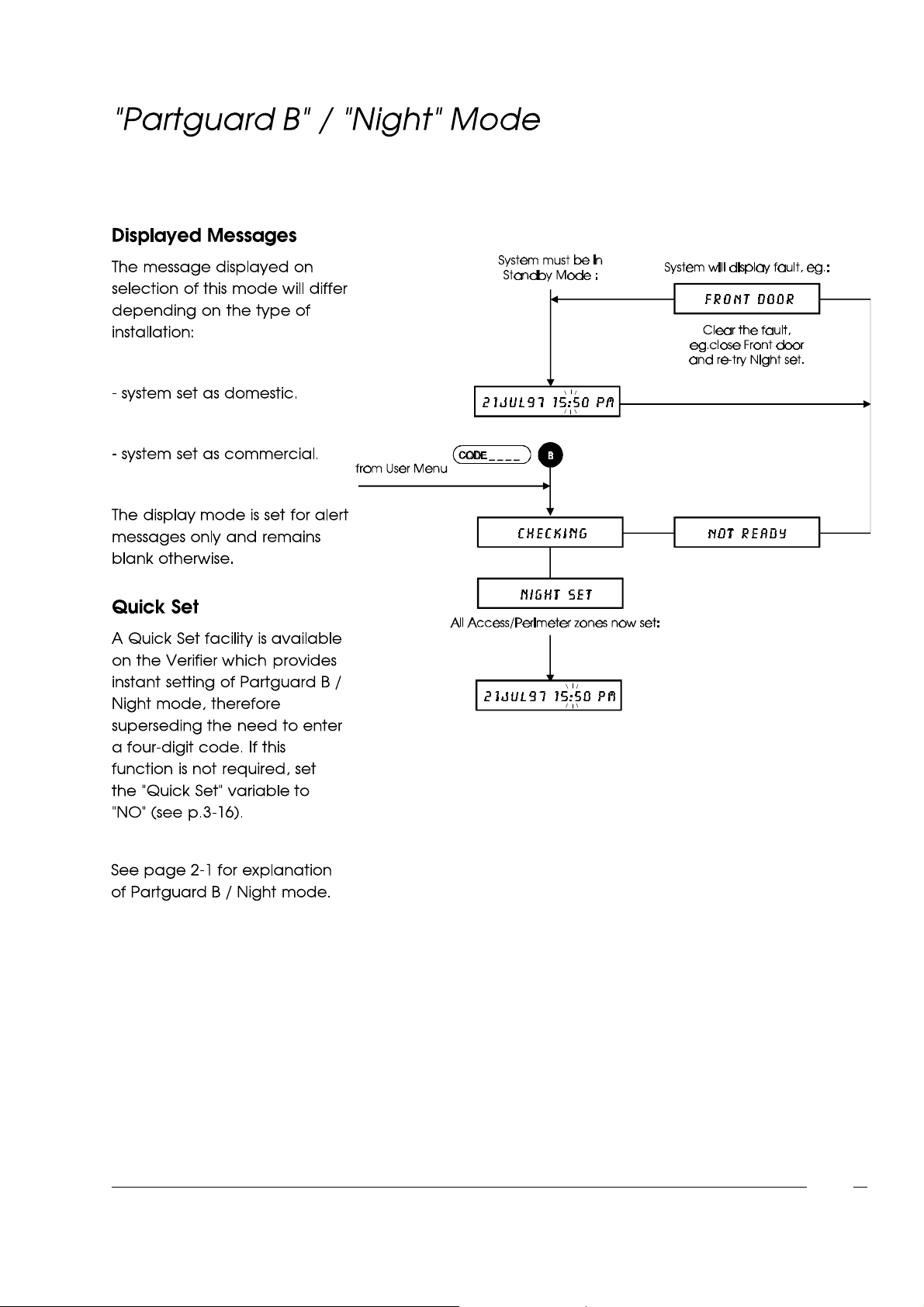
NIGHT ?
PARTGUARD B ?
User Menu
4-13
Page 72
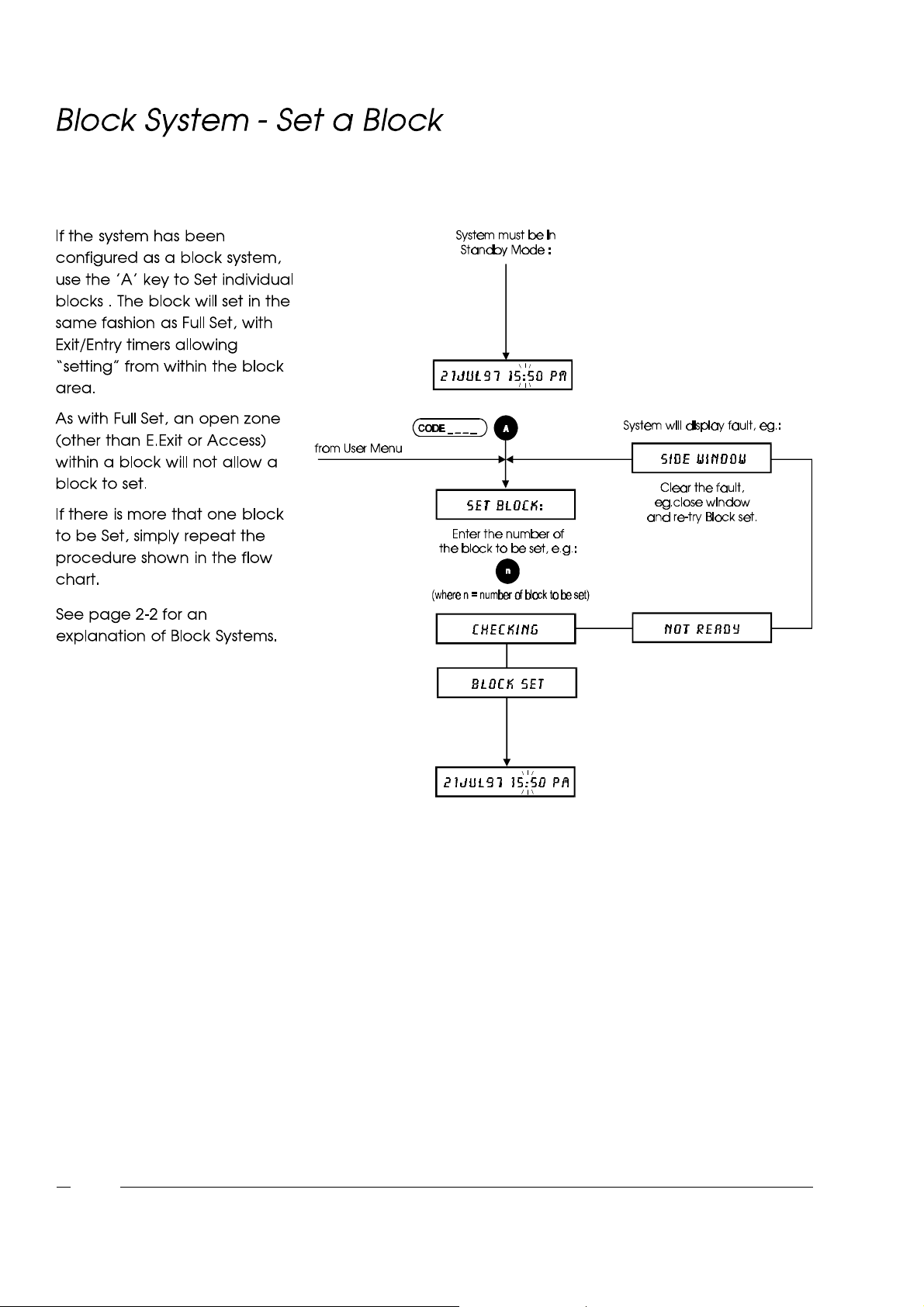
User Menu
4-14
Page 73
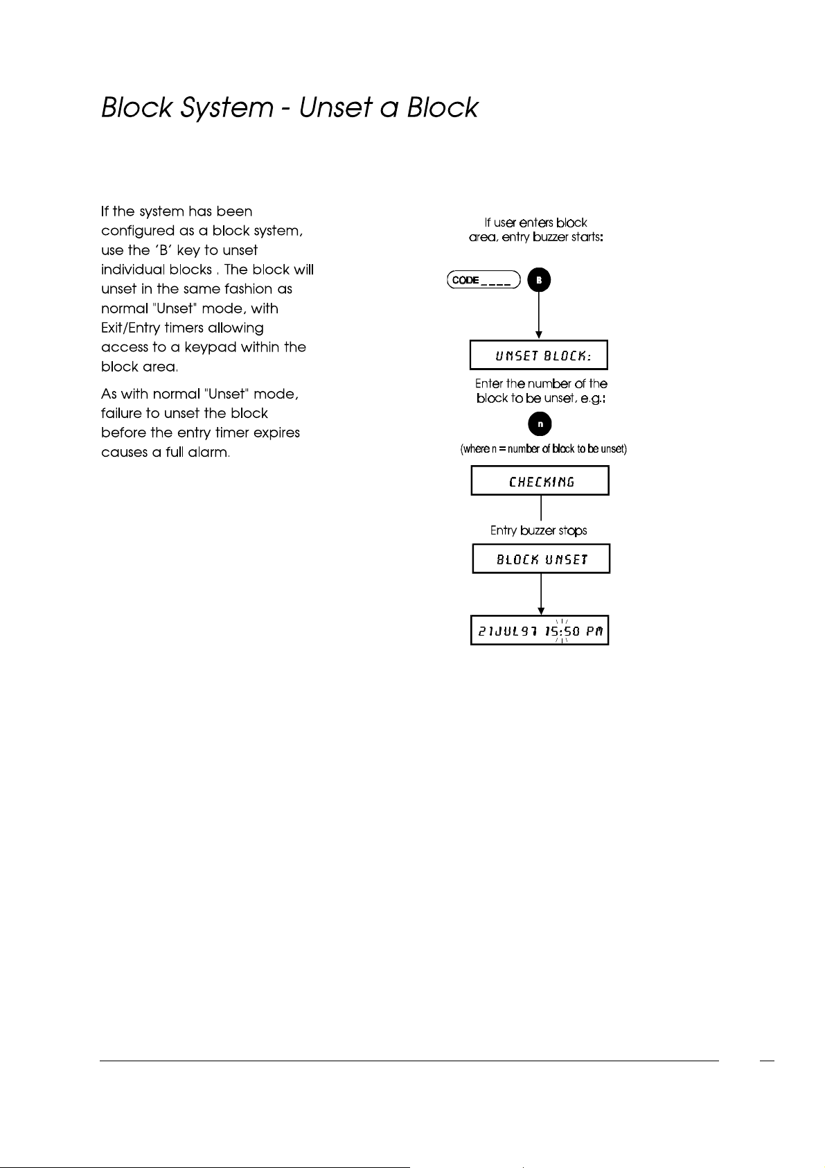
User Menu
4-15
Page 74
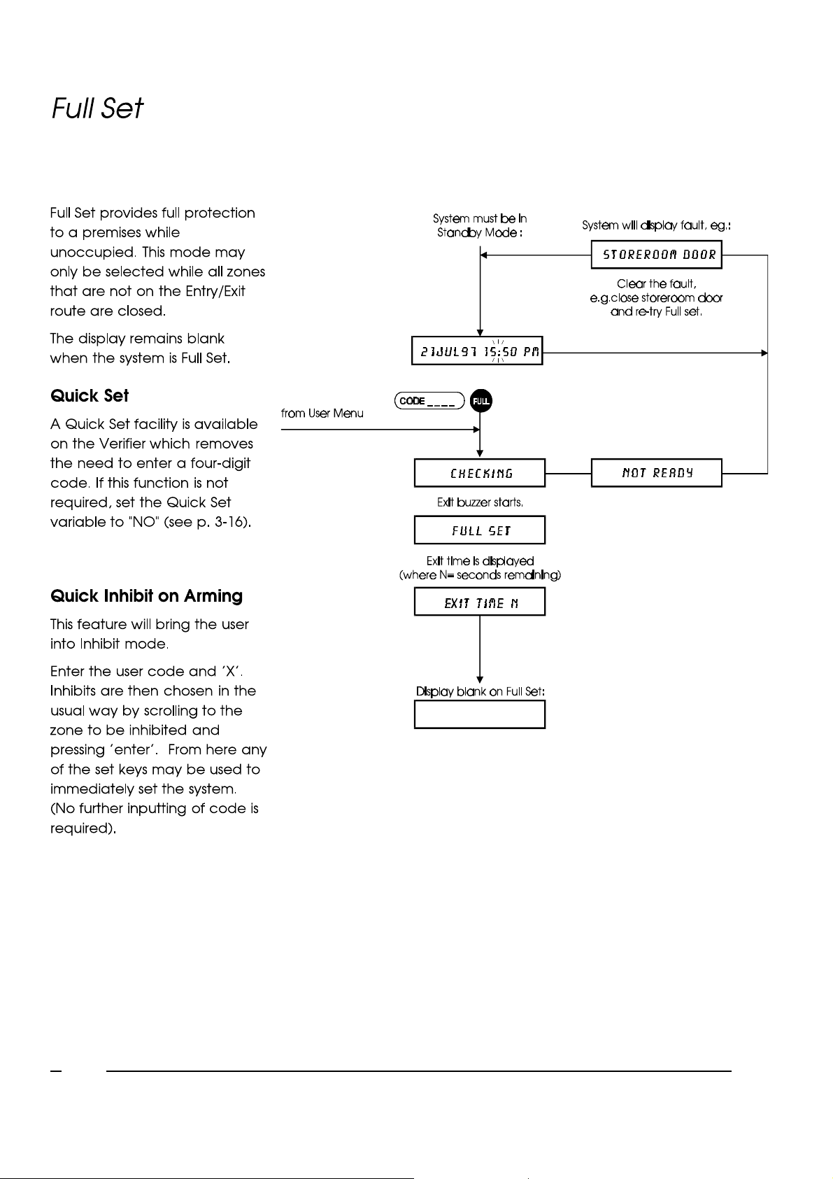
User Menu
4-16
Page 75
ChapterFive
Page 76

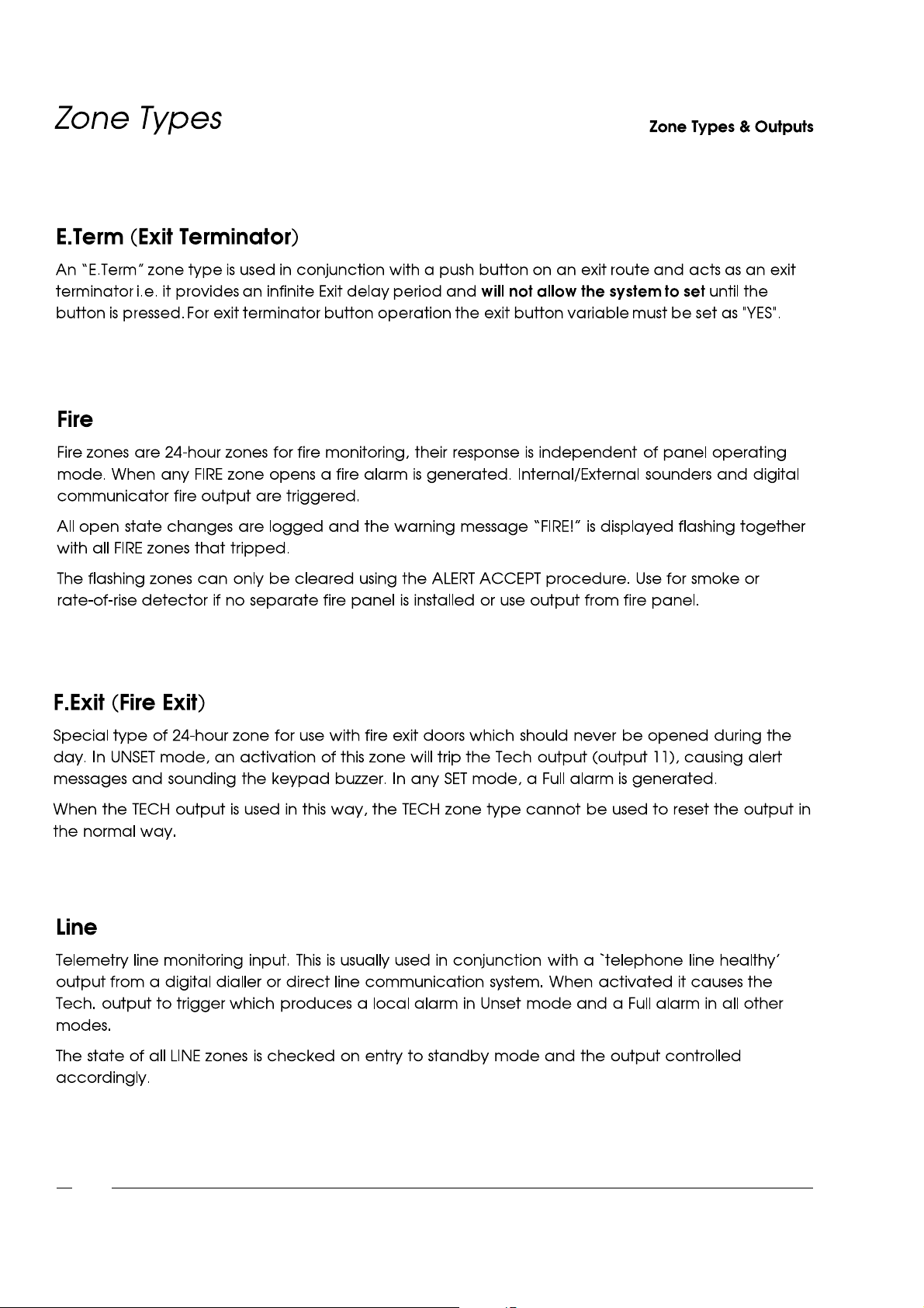
Note: A TAMPER or DISCON condition for any zone type will cause a local alarm in Unset mode and a Full alarm
in any other mode.
Attributes(that may be applied) :
Access, Exclude A, Exclude B, 24-hour, Double, Pair, Chime, Local, Inhibit.
Attributes:
Access, Exclude_A, Exclude_B, Chime, Local, Inhibit.
5-1
Page 77
Attributes: Inhibit
Attributes: Local
Attributes: Local, Inhibit
Attributes: Inhibit
5-2
Page 78

Attributes: None
l
l
l
Attributes: None
l
l
l
l
l
Attributes: Inhibit
Attributes: Chime, Inhibit
5-3
Page 79
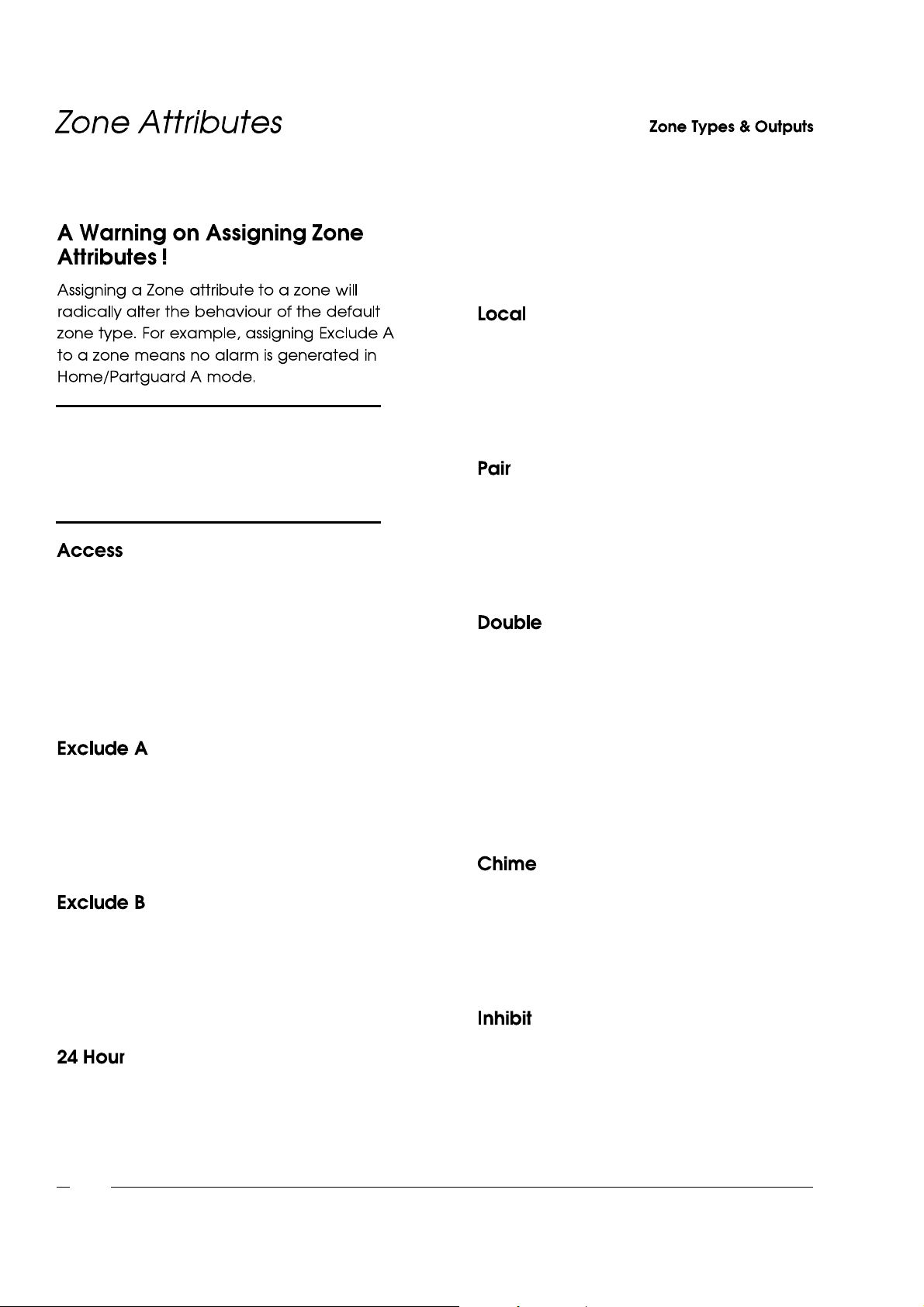
Note: Read this section thoroughly before
attempting to assign an attribute and
then calculatethe consequencesof
altering a zone's behaviour and TEST
for ALL possible permutations.
When the Access attribute is set, an alarm will
not be generated by the zone opening while
either of the entry or exit timers are running. In
addition, in Night mode, the zone behaviour
changes to that of an E.EXIT zone. The Access
attribute is valid for ALARM zone types and
E/Exit zones only.
When the Exclude A attribute is set, an alarm
will not be generated by the zone opening
while the panel is in the Partguard A or Home
mode. The Exclude A attribute is valid for
ALARM zone type and E/Exit zones only.
tripped. This Attribute overrides the Access
and Exclude A/B attributes and is valid only for
ALARM zone type.
When the Local attribute is set, an alarm
generated by the zone opening will not result in
the digi dialler output being tripped. The Local
attribute is valid for ALARM, E.EXIT, FIRE and
F.EXIT zone types.
When the Pair attribute is set, an alarm will not
be generated by the zone opening unless at
least one other zone with the Pair attribute has
opened since the panel was set. The Pair
attribute is valid for ALARM zone type only.
When the Double attribute is set, an alarm will
not be generated by the zone unless it is the
second activation of a Double zone within the
time period specified for the double knock timer.
The Double attribute is valid for ALARM zone
type only. If both the Pair and Double attributes
are set for a zone, then an alarm activation will
occur if either of the Double or Pair conditions
are met.
When the Exclude B attribute is set, an alarm
will not be generated by the zone opening
while the panel is in the Partguard B or Night
mode. The Exclude B attribute is valid for
ALARM zone type and E/Exit zones only.
When the 24 Hour attribute is set, the zone
opening will generate an alarm in all modes
except UNSET, in which a digi output will be
5-4
When the Chime attribute is set for a zone(s),
any opening of the zone during the Unset mode
will cause the internal buzzers to activate for a
short period. The Chime attribute is valid for
ALARM, E.EXIT and TECH zones.
When the Inhibit attribute is set, a user may
inhibit this zone in Inhibit mode. Otherwise this
zone is prevented from being inhibited.
Page 80
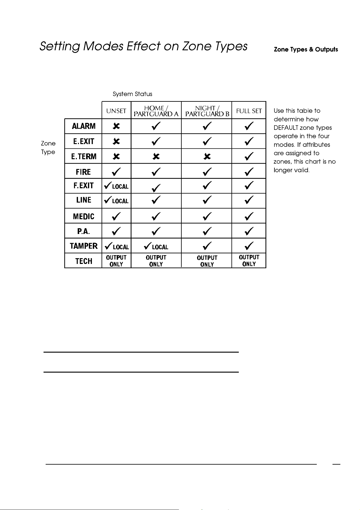
Not Active = û
Active = ü
Local Alarm Only = LOCAL
WARNING! Assigning Attributeswill radically alterthe behaviour of zone
types, in which case this table is invalid.
5-5
Page 81
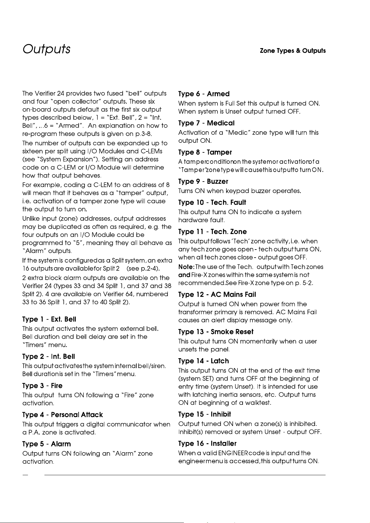
5-6
Page 82

ChapterSix
Page 83
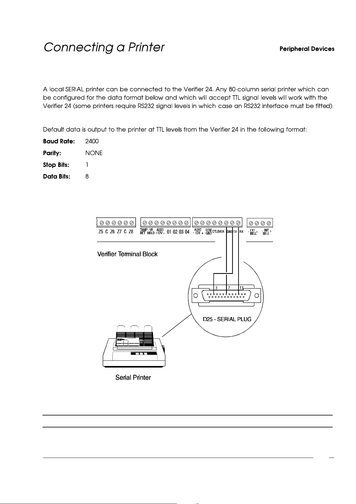
Fig. 21 - Connecting a Serial Printer
IMPORTANT: The maximum distance between the VerifierControl Panel and Printer should not exceed 25 Metres.
6-1
Page 84
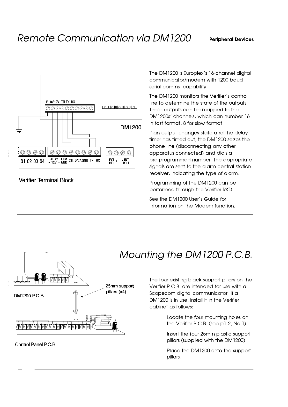
Fig. 22 - Connecting a DM1200
Important: When connecting remote communication devices for use with PC software,a Modem MUST be connected
at the PC and a DM1200 MUST be connected at the panel. Any other configuration is NOT acceptable.
l
l
6-2
l
Fig. 23 - Mounting a DM1200
Page 85
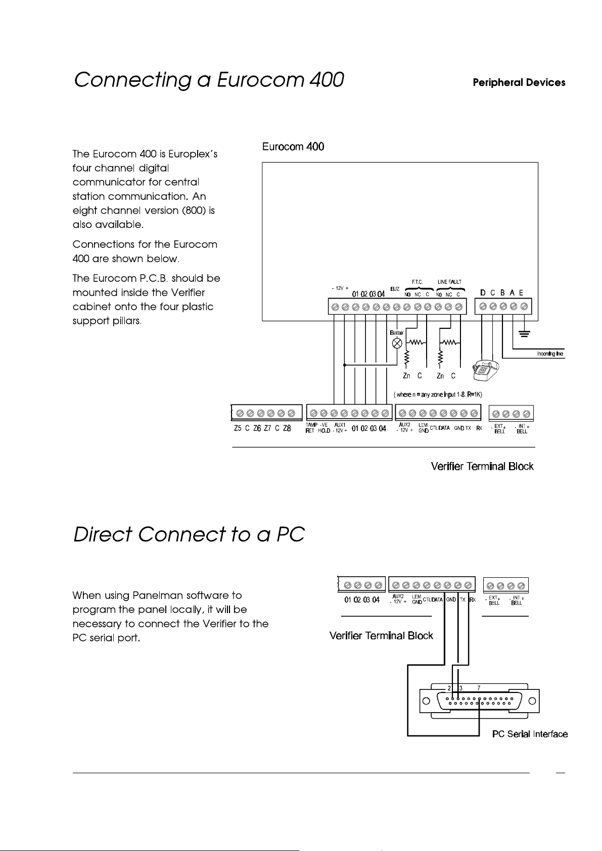
Fig. 24 - Connecting a Eurocom
Fig. 25 - Direct Connect to a PC
6-3
Page 86
6-4
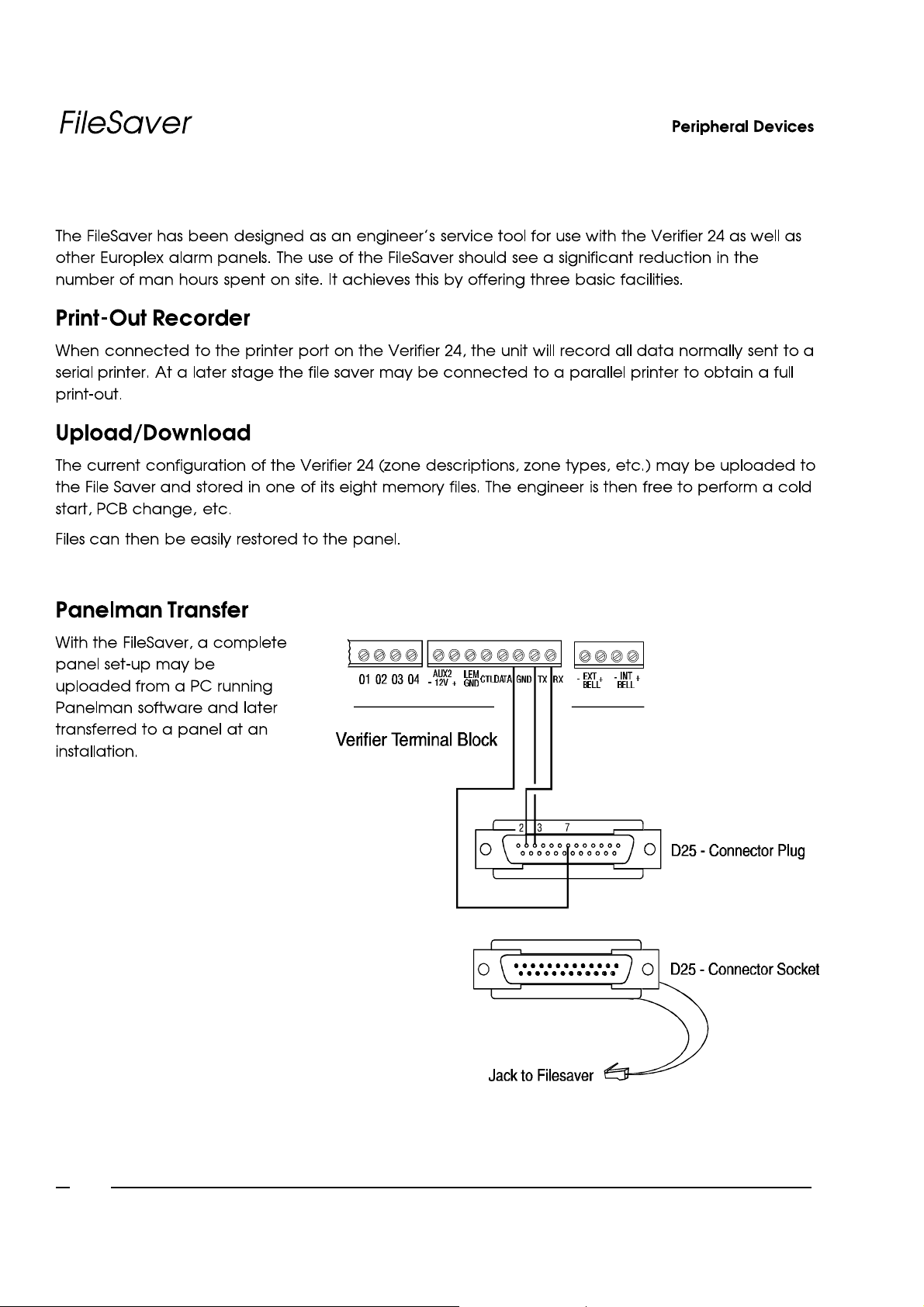
Fig. 26 - Connecting a Filesaver
 Loading...